


Bosch K-Jetronic Fuel Injection Part 2
Fuel Management
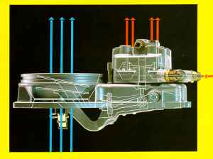
Mixture control unit
The task of fuel management is to meter, or
allocate, the correct quantity of fuel which corresponds to the amount of air
drawn in by the engine. Fuel management carried out by the mixture control
unit. This comprises the air-flow sensor and the fuel distributor.
Air-flow sensor
The air-flow sensor operates according to the
suspended-body principle and measures the amount of air drawn in by the engine.
All the air drawn in by the engine flows through an air-flow sensor which is
connected upstream of the throttle plate. The air-flow sensor is fitted with an
air funnel in which is located a movable sensor plate (the suspended body). The
air drawn in through the air funnel shifts the sensor plate by a certain amount
out of its zero position. The movement of the sensor plate is transmitted to a
control plunger by a lever system. This plunger determines the quantity of fuel
required. Considerable pressure shocks can occur in the intake system if
backfiring takes place in the intake manifold. For this reason, the airflow
sensor is so designed that the sensor plate can swing back in the opposite
direction, past its zero position, and thus open a relief cross-section in the
funnel. A rubber buffer limits the swing-back in the downward direction (in the
case of the updraft air-flow sensor, the swing-back in the upwards direction is
also limited by a rubber buffer). A leaf spring ensures that the sensor plate
assumes the correct zero position when the engine is stationary. The
sensor-plate movements are transmitted to the control plunger in the fuel
distributor by means of a lever system. The weight of the sensor plate and the
lever system are balanced by a counterweight.
Fuel distributor
The fuel distributor meters (allocates) the
correct amount of fuel to the individual cylinders in accordance with the
position of the air-flow sensor plate. As already mentioned, the position of
the sensor plate is a measure of the amount of air drawn in by the engine. The
position of the plate is transmitted to the control plunger by a lever. The
control plunger controls the amount of fuel which is to be injected. Depending
upon its position in the barrel with metering slits, the control plunger opens
or closes the slits to a greater or lesser degree. The fuel flows through the
open section of these slits to the differential pressure valves and then to the
fuel-injection valves. If sensor-plate travel is only small, then the control
plunger is only lifted slightly and as a result only a small section of the
slot is opened for the passage of fuel. With larger plunger travel, the plunger
opens a larger section of the slits and more fuel can flow. There is,
therefore, a linear relationship between sensor-plate travel and the slit
section in the barrel, which is opened for fuel flow. The force applied to the
control plunger by the sensor plate travel is opposed by another force, which
comes from the so-called control pressure. One of the functions of this control
pressure is to ensure that the control plunger follows the movements of the
sensor plate immediately and does not, for instance, stay in the (upper) end
position when the sensor plate moves back down again. Further important
functions of the control pressure are discussed in the chapters dealing with
warm-up and full-load enrichment
Control pressure
The control pressure is tapped off from the
primary pressure through a restriction bore, which serves to decouple the
control-pressure circuit and the primary pressure circuit from one another. A
connection line joins the fuel distributor and the warm-up regulator (control
pressure regulator). When starting the cold engine the control pressure is
about 0.5 bar. As the engine warms up, the warm-up regulator increases the
control pressure to about 3.7 bar. The control pressure acts through a damping
restriction on the control plunger and thereby develops the force, which
opposes the force of the air in the air-flow sensor. In doing so, the
restriction dampens a possible oscillation of the sensor plate, which could
result due to pulsating air-intake flow. The control pressure influences the
fuel distribution. If the control pressure is low, the air drawn in by the
engine can deflect the sensor plate further. This results in the control
plunger opening the metering slits further and the engine being allocated more
fuel. On the other hand, if the control pressure is high the air drawn in by
the engine cannot deflect the sensor plate so far and, as a result, the engine
receives less fuel. In order to fully seal off the control pressure circuit
with absolute certainty when the engine has been switched off, and at the same
time to maintain the pressure in the fuel circuit, the return line of the
warm-up regulator is fitted with a non-return valve. This (push-up) valve is
actually in the primary-pressure regulator and is held open during operation by
the pressure-regulator plunger. When the engine is switched off and the plunger
of the primary-pressure regulator returns to its zero position, the non-return
valve is closed by a spring.
Differential-pressure valves
The differential-pressure valves in the fuel
distributor serve to hold the drop in pressure at the metering slits constant.
The air-flow sensor has a linear characteristic. This means that if double the
quantity of air is drawn in, the sensor-plate travel is also doubled. If this
(linear) travel is to result in a change of delivered fuel in the same
relationship, in this case double the travel = double the quantity, then a
constant drop in pressure must be guaranteed at the metering slits independent
of the amount of fuel flowing through them. The differential-pressure valves
maintain the drop in pressure at the metering slits constant independent of
fuel through flow. The difference in pressure is 0.1 bar, this facilitates a
high degree of control accuracy. The differential-pressure valves are of the
flat-seat type. They are fitted in the fuel distributor and one such valve is
allocated to each metering slit. The upper and lower chambers of the valve are
separated by a diaphragm. The lower chambers of all the valves are connected
with one another by a ring main and are subjected to the primary pressure
(delivery pressure from fuel-supply pump). The valve seat is located in the
upper chamber. Each upper chamber is connected to a metering slit and its
corresponding fuel-injection line. The upper chambers are completely sealed off
from each other. The diaphragms are spring-loaded and it is this helical spring
that produces the pressure differential. If more fuel flows into the upper
chamber through the metering slit, the diaphragm is bent downwards and enlarges
the valve cross-section at the outlet line leading to the injection valve until
the differential pressure of 0.1 bar set by the spring again prevails. If less
fuel flows, the diaphragm bends back towards its original position and
decreases the valve cross-section at the outlet line until the differential
pressure of 0.1 bar is again present. This causes an equilibrium of forces to
prevail at the diaphragm which can be maintained for every quantity of fuel by
controlling the valve cross-section.
Mixture formation
The formation of the air-fuel mixture takes place
in the intake manifold (tubes) and cylinders of the engine. The continually
injected fuel coming from the injection valves is "stored" in front of the
intake valves. When the intake valve is opened, the air drawn in by the engine
carries the waiting "cloud" of fuel with it into the cylinder. An ignitable
air-fuel mixture is formed during the induction stroke due to the swirl effect.
Mixture Adaptation
In addition to the basic functions described up to now, the mixture has to be adapted during particular operating conditions. These adaptations (corrections) are necessary in order to optimise the power delivered, to improve the exhaust-gas composition and to improve the starting behaviour and driveability
Cold start
Depending upon the engine temperature, the start
valve injects extra fuel into the intake manifold for a limited period during
the starting process. During cold starting, part of the fuel in the mixture
drawn in is lost due to condensation on the cold cylinder walls. In order to
compensate for this loss and to facilitate starting the cold engine, extra fuel
must be injected at the instant of start-up. This extra fuel is injected by the
start valve into the intake manifold. The injection period of the start valve
is limited by a thermo-time switch depending upon the engine temperature. This
process is known as cold-start enrichment and results in a "richer" air-fuel
mixture, i.e. the excess-air factor is temporarily less than 1.
Start valve
The start valve is of the solenoid-operated type.
The winding of an electromagnet is fitted inside the valve. In the inoperated
state, the movable armature of the electromagnet is forced against a seal by
means of a spring and thus closes the valve. When the electromagnet is
energised, the armature which as a result has lifted from the valve seat opens
the passage for the flow of fuel through the valve. From here, the fuel enters
a special nozzle at a tangent and is caused to rotate. The fuel is particularly
well atomised by this specially shaped nozzle - the so-called "swirl nozzle" -
and enriches the air in the intake manifold, downstream of the throttle valve,
with fuel.
Thermo-time switch
The thermo-time switch limits the injection period
of the start valve dependent upon engine temperature. It is comprised of an
electrically heated bimetal strip which depending upon its temperature either
opens or closes an electric contact. The complete device is fitted into a
hollow threaded pin which in turn is located at a position where typical engine
temperature prevails. The thermo-time switch determines the injection period of
the start valve. In doing so, the warming-up of the switch due both to the
engine heat and to the surrounding temperature, as well as its in-built
electrical heating filament are the determining factors. The in-built heating
facility is necessary in order to limit the maximum start-valve injection
period. The mixture would otherwise become too rich and the engine would not
start due to "flooding". During cold start the injection period depends mainly
upon the electrical heating facility. (Switch off at -20°C after approx. 8
seconds). On the other hand, when the engine is already warmed-up the heat from
the engine has heated the thermo-time switch to such a degree that it remains
permanently open. As a result, an engine which is already at operating
temperature is not provided with extra fuel for starting.
Warm-up
Warm-up enrichment is controlled by the warm-up
regulator. When the engine is cold the warm-up regulator reduces the control
pressure to a degree dependent upon engine temperature and thus causes the
metering slits to open further. At the beginning of the warm-up period which
directly follows the cold start, some of the injected fuel still condenses on
the cylinder walls and in the intake ports. This can cause combustion miss to
occur. For this reason, the air-fuel mixture must be enriched during the
warm-up phase (Lambda<1.0). This enrichment must be continuously reduced
along with the rise in engine temperature in order to prevent the mixture being
over-rich when higher engine temperatures have been reached. The warm-up
regulator (control-pressure regulator) is the component which carries out this
mixture control for the warm -up period by changing the control pressure.
Warm-up regulator
The change of the control pressure is effected by
the warm-up regulator which is so fitted to the engine that it ultimately
adopts the engine temperature. In addition, the warm-up regulator is
electrically heated which enables it to be precisely matched to the engine
characteristic. It comprises a spring-controlled flat seat diaphragm-type valve
and an electrically heated bimetal spring. In the cold state the bimetal spring
exerts an opposing force to that of the valve spring and, as a result, reduces
the effective pressure applied to the underside of the valve diaphragm. This
means that the valve outlet cross-section is slightly increased at this point
and more fuel is diverted out of the control-pressure circuit in order to
achieve a low control pressure. As soon as the engine is cranked the bimetal
spring is heated electrically and after starting it is also heated by the
engine. The spring bends, and in doing so reduces the force opposing the valve
spring which, as a result, pushes up the diaphragm of the flat-seat valve. The
valve outlet cross section is reduced and the pressure in the control-pressure
circuit rises. Warm-up enrichment is completed when the bimetal spring has
lifted fully from the valve spring. The control pressure is now solely
controlled by the valve spring and maintained at its normal level. The control
pressure is about 0.5 bar at cold start and about 3.7 bar with the engine at
operating temperature.
Auxiliary-air device
In order to overcome the increased friction in the
cold state and to guarantee smooth idling, the engine receives more air-fuel
mixture during the warm-up phase due to the action of the auxiliary-air device.
When the engine is cold, the frictional resistances are higher than when it is
at operating temperature. These must also be overcome by the engine during
idle. For this reason, the engine is allowed to draw in more air by means of
the auxiliary-air device which by-passes the throttle valve. Due to the fact
that this auxiliary air is measured by the air-flow sensor and taken into
account for fuel metering, the engine is provided with more air-fuel mixture.
This results in idle stabilisation when the engine is cold. In the
auxiliary-air device a perforated plate is pivoted by means of a bimetal spring
and changes the open cross section of the bypass line. Dependent upon
temperature the plate assumes a given position, so that in the case of a cold
engine a correspondingly larger cross section of the bypass line is opened. As
the temperature increases the open area is decreased until, finally, it is
closed completely. The bimetal is heated electrically. This means that the
opening time can be limited according to engine type. The auxiliary-air device
is so located that it is heated up by the engine to the engine temperature.
This ensures that the auxiliary-air device does not respond when the engine is
warm.
Load conditions
The adaptation, or correction, of the air-fuel
mixture to the operating conditions of idle, part load and full load is carried
out by means of appropriately shaping the air funnel in the air-flow sensor. If
the funnel had a purely conical shape, the result would be a mixture with a
constant air-fuel ratio throughout the whole of the sensor plate range of
travel (metering range). As has already been mentioned though, it is necessary
to meter to the engine an air-fuel mixture which is optimal for particular
operating conditions such as idle, part load and full load. In practice, this
means a richer mixture at idle and full load, and a leaner mixture in the
part-load range. This adaptation is achieved by designing the air funnel so
that it becomes wider in stages If the cone shape of the funnel is flatter than
the basic cone shape (which was specified for a particular mixture, e.g. for
Lambda= 1) this results in a leaner mixture. If the funnel walls are steeper
than in the basic model the sensor plate is lifted further for the same air
throughput, more fuel is therefore metered and the mixture is richer. Hence,
the funnel is so shaped that a richer mixture is produced at idle and full
load, and a leaner mixture at part load (full-load and idle enrichment).
Mixture enrichment by means of control-pressure reduction In those cases where engines are operated with a very lean mixture in the part load range, an extra mixture enrichment must be provided at full load in addition to the mixture adaptation resulting from the shape of the air funnel. This extra enrichment is carried out by a specially designed warm-up regulator. This regulates the control pressure depending upon the manifold pressure. In this model of the warm-up regulator, two valve springs are used instead of one. The outer of the two springs is supported on the housing as is the case with the normal-model warm-up regulator. The inner spring though, is supported on a diaphragm which divides the regulator into an upper and a lower chamber. The manifold pressure is effective in the upper chamber which is connected to the intake manifold, behind the throttle valve, by means of a hose. Depending upon the model, the lower chamber is subjected to atmospheric pressure either directly or by means of a second hose leading to the air filter. Due to the low manifold pressure in the idle and part-load ranges, which is also present in the upper chamber, the diaphragm lifts to its upper stop. The inner spring is now at maximum pretension. The pretension of both springs, as a result, determines the particular control pressure for these two ranges. When the throttle valve is opened further at full load, the pressure in the intake manifold increases, the diaphragm leaves the upper stops and is pressed against the lower stops. The inner spring is relieved of tension and the control pressure reduced by the specified amount as a result. In this manner, mixture enrichment is achieved.
Acceleration response
The good acceleration response is a result of the
sensor plate "overswing". Acceleration During the transition from one operating
condition to the other, changes in the mixture ratio occur which are utilised
to improve the driveability. If at constant engine speed the throttle valve is
suddenly opened, the amount of air which enters the combustion chamber, plus
the amount of air which is needed to bring the manifold pressure up to the new
level, flow through the airflow sensor. This causes the sensor plate to briefly
"overswing" past the fully opened throttle point. This "overswing" results in
more fuel being metered to the engine (acceleration enrichment) and ensures
good acceleration response.
Controlling the air-fuel mixture
In order to adapt the injected fuel quantity to
the ideal air-fuel ratio of Lambda= 1, the pressure in the lower chambers of
the fuel distributor is varied. If for instance the pressure is reduced, the
differential pressure at the metering slots climbs accordingly with the result
that the injected fuel quantity is also increased. In order to be able to vary
the pressure in the lower chambers, these are decoupled (in contrast to the
conventional K-Jetronic fuel distributor) from the primary pressure. Decoupling
is by means of a fixed throttle. A further throttle connects the lower chambers
with the fuel return. This throttle is variable. If it is open, the pressure in
the lower chambers can reduce. If it is closed, the primary pressure is present
in the lower chambers. If this throttle is opened and closed rapidly, it is
possible to vary the pressure in the lower chambers to correspond to the ratio
between open time and close time. An electromagnetic valve, the timing valve,
is used as the variable throttle. It is controlled by electrical pulses from
the Lambda control unit.
Remember to take all necessary safety precautions when working on your car.
Legal | Privacy | Contact Us | Search | Site Map
Volvo Owners' Club Limited® 1962-2026