Cooling System Maintenance
Coolant and Maintenance:
Changing Coolant on 960 B6300 Engines
Radiator and Cooling System Lifetime
Overheating: Radiator Fin Cleaning
Hoses:
Water Pump:
Water Pump Change on B280 Engine
Radiators and Components:
Loss of Coolant and Overheating:
Coolant Loss: How to Diagnose?
Sudden Loss of Coolant and Engine Overheating Incidents
Loss of Coolant and Possible Head Gasket Leaks
Troubleshooting:
Oil in Coolant Reservoir Bottle
Temp Gauge Acts Oddly: Leaking Headgasket?
Heater Core/Radiator Repeat Failures: Electrolysis or Head Gasket Leaks
Gauge Shows Intermittent Redline
Coolant Sensor Loose in Replacement Metal Radiator
Electric Cooling Fan Operation
960 B6304 Coolant Loss: Coolant Cap At Fault
Homemade Cooling System Pressure Tester
Coolant and Maintenance:
Coolant Recommendations. See the FAQ File with more technical information about coolants. [Editor] Folks have tried various coolants in place of the Volvo Blue-Green, which is expensive. Your choice falls into three categories:
- Highly-silicated conventional green antifreeze (e.g., Prestone and many other brands)
- Dexcool orange with no silicates and organic acid corrosion protection (e.g., Havoline Dexcool and Prestone Dexcool)
- Glysantin orange-yellow with low silicates and organic acid corrosion protection (e.g., Zerex Extreme G-05)
My own experience with Dexcool has been positive with one exception: the solder in a Nissen brass radiator began leaking . Dexcool is known to have problems with high-lead solders, and is also sensitive to air levels in cooling systems. If you don't keep the system topped off to the "min" mark on the reservoir, it may cause scaling and rust precipitation. The last Glysantin alternative is new in the US, although well-known in Europe, and may be the optimal replacement coolant for Volvo. It has a small amount of silicates to improve corrosion protection for lead and aluminum, but not so much as to precipitate out, and in addition uses an OAT package. This is your best bet, but it is tougher to find.
Dexcool Coolant: [From the AC-Delco site:] Neon orange in color, the coolant lasts up to five years or 150,000 miles, whichever comes first. Conventional coolants need to be replaced every two years/30,000 miles. DEX-COOL's benefits include: Lower maintenance costs, due to longer change intervals; enhanced component durability -- improved water pump seal performance and superior heat exchanger protection over regular-life coolants; recyclability. Note: DEX-COOL's unique orange color acts as a reminder not to mix the new formula with conventional coolant (usually green in color). Although it won't damage your car's cooling system when mixed with other coolants, DEX-COOL will lose some of its effectiveness. (Warning: Do not use DEX-COOL with Cooling System Seal Tabs, Radiator Fast Flush or Radiator Stop Leak.)
[Motor Magazine, Aug 2004] One of the coolant issues that may arise is the use of an aftermarket replacement radiator or heater core made of copper-brass with lead solder. We have in previous articles pointed out that today's coolant inhibitor packages contain a small amount of copper-brass protection, but may provide little protection if a radiator is made with high-lead solder. Results of industry standard tests of the new Toyota extended-life coolant now show a substantial weight loss (corrosion), both in a 50-50 mix and in a 33% coolant mixture (solder corrosion is much greater in this more diluted solution). If you have to change a radiator or heater core, use aluminum. Or, if it's an older car and the owner wants the lowest-cost radiator, you might procure a soldered-together copper-brass unit. Conventional American coolant should provide better protection against solder corrosion, which can result in radiator tube restrictions and leaks. But no coolant provides perfect protection
[Ywan Mason] Dex-Cool, according to a GM service bulletin only gives the extended life when it was used as the first and only coolant in the car. Residual amounts of conventional coolants left in the system even after careful draining require that the Dex-Cool be changed at the same interval as any other coolant, every two years.
[Chris Herbst] Dexcool can cause problems if installed in a leaky system, or if it is used in a system run low on coolant. Also, it finds leaks where typically none previously occurred.
Zerex G-05:
This is Valvoline's new Zerex coolant, known as Extreme G-05. From their website: Extreme G-05 is a low-silicate, low-pH, phosphate-free, formula that is designed to protect diesel engine cylinder liners from cavitation. Extreme G05 is safe for both gasoline and diesel engines and is approved by DaimlerChrysler for worldwide MTU applications. Utilizes hybrid organic acid technology to minimize inhibitor depletion; Low-silicate, low-pH and phosphate-free formula; Protects all cooling system metals, including aluminum
Makeup Water. [Tip from Prestone's Info Line] We would consider the order of preference for water to be as follows:
- 1st choice: Type IV water- Both demineralized & Deionized.
- Next choice: Distilled water
- Next choice: Bottled water (like the type at a grocery store)
- Last choice: Tap water
Which Coolant to Use? See the discussion on Coolant Recommendations .
Block Drain Plugs Location.
B230F/T.[Inquiry:] B230F - I want to flush the cooling system, but the only block drain I see is a threaded male plug on the RH side of the block (kinda high) below exhaust manifold runners 1 and 2. Is that all there is?
[Response: Randy] Look for the block drain on the passenger's side of the block, #4 cylinder back just above the oil pan and in front of the transmission bellhousing. 13mm wrench will loosen, continue to turn counterclockwise and the coolant will flow out. You can attach a hose and run it into a container with about a 2 gallon capacity. If it hasn't been used in some time you may have to clean it out to get a good flow. You can also unscrew the entire drain. Open the reservoir cap to increase flow. You will not be able to remove all the coolant: it always seems as though about two quarts remains in the system. On the 940Turbo: the coolant drain is at the end of the short hose leading from the oil cooler, about five inches behind the oil filter beneath the car. It points down from the tubing on which it is mounted.
B6300. The petcock to drain the engine coolant is behind the water pump near the pipe that connects to the oil cooler line.
Draining Coolant.
[Inquiry:] I must be missing something here. My 944 needed an antifreeze flush and refill, so off I went. I set the heater on "high", disconnected the vacuum to the water valve to make sure it was open, disconnected the upper and lower radiator hoses and drained a large quantity of coolant out of the radiator, water pump and overflow bottle. The heater hose was stuck on to the firewall pipe; not wanting to cut the hose, I did not disconnect it, thinking that the upper radiator hose disconnection would encourage the head and heater to drain. I also drained the block via the block plug screw. After refilling and draining again once, I put in what I thought was exactly half (5 qts) of the system capacity in new Dexcool antifreeze. This filled the system, so I obviously had another five qts of undrained water sitting in there somewhere. Has anyone figured out how to drain the cooling system down to zero? Can the heater actually hold that much fluid?
[Response:] You will never be able to get all the coolant out. Have you ever replaced an engine thinking you got all the fluids out only to have a mess all over the floor. The engine has areas that can't be drained unless the block is tipped over. You did as thoroughly as the job can be done. When refilling premix the coolant so that when you top off, the mixture is still 50/50 . [Tip from Phil Connell] I put my shop vac on "blow" and stuck the nozzle in the upper radiator hose and blew all the water out of the engine. This is one technique to remove water in the heater core and hoses that otherwise would not drain by gravity.
Engine Flush Procedure.
[KenC] For a thorough flush, try this technique. You will need sockets for the clamps' nuts, a garden hose and a couple of feet of 1" I.D. RBU (reinforced with braided vinyl) or solid vinyl transparent hose (transparent, so you can see the quality of the water coming out). This hose is available in all hardware/plumbing stores, and it's external diameter lets it snugly fit into the upper radiator hose forming a good connection.
- Turn the heater temperature control to "hot" to open the water valve.
- Drain the cooling system (preferably when cool, so there won't be a temperature shock or overheating to the engine). If you can reach the engine block drain, so much the better, but at least pull off the lower radiator hose where it goes in the radiator. Be careful pulling off this hose so you don't break the plastic outlet.
- Remove the thermostat and then reinstall the thermostat housing without the thermostat. Don't worry about a gasket -- there's no pressure in this process, so just finger tighten the two nuts. And throw away the old thermostat -- treat the car to a new one and its gasket, after all this effort, it deserves it.
- After draining, slip the lower radiator hose back onto the radiator's "neck", but don't bother with a clamp (again, no pressure).
- Pull off the upper radiator hose from the thermostat housing. Now, stick the transparent hose into the housing, so that the transparent hose extends forward over the radiator (so discharged coolant doesn't fall into the engine compartment) -- later you'll be watching the appearance of the coolant in the hose before being discharged, a more reliable view than watching the stream of coolant. Be careful in this process that you do not lean on or crack the plastic upper radiator hose inlet: it can be brittle.
- Wrap a little tape around the end of an ordinary garden hose, and jam it (gently) into the open end of the upper radiator hose -- it will fit nicely. Now, turn on the garden hose's water supply.
- Watch as the fresh water circulates throughout the cooling system, flushing out the old stuff. Keep an eye on the color of the solution in the transparent hose before it spills out. You can even turn on and run the engine (at idle, only) to use the engine's water pump to help circulate the fresh water and dislodge heavier debris. But don't rev the engine, as the garden hose usually can't keep up with the pump's needs, and you'll get pump cavitation.
- After it's thoroughly flushed, drain all the "garden hose water" in the system by pulling off lower radiator hose and opening the block drains.
- Re-attach proper hoses with tightened clamps, install a fresh thermostat, and then refill with a good quality antifreeze (about a gallon of antifreeze to similar amount of distilled water -- depending on your model engine.
An Alternative Flush Procedure.
[Robert Ludwick]. You should have a block drain with a nipple on it on the passenger side at the rear of the block (or, for turbos, a coolant drain fitting in the bottom of the u-shaped hose near the oil filter). Go to the hardware store and get a piece of clear vinyl hose to fit it, a couple of clamps, and a garden hose end fitting and attach it to the hose. Remove the thermostat housing and the thermostat and replace the housing. Remove the coolant reservoir cap. Turn on the hose and the system will be flushed up and out the reservoir. To drain the system afterward, remove the block drain and the pump end of the lower radiator hose, bending it down to drain the water.
After flushing just hook the system back up and pour 1 quart of 100% coolant into the coolant reservoir (to mix with residual water in the block and heater core), then top up with a 50-50 coolant/distilled water mix.
Flushing After Oil Leakage from Headgasket Failure. [Chuck Jeckell] How do I remove oil that has seeped into the cooling system after my headgasket failed? [ ] Porsche has a service bulletin that says use Shout detergent. i've had to do it to a couple of cars over the years, works well. just flush well with water before filling for good. The water pump can still churn suds out of the remainder.
Bleeding Air from the Cooling System
[Inquiry] After replacing a thermostat or water pump, how do I bleed the air out?
[Response: Jim McDonald] Very little bleeding should be necessary if you put the thermostat in with the "wiggle valve"[air vent] in the right position[up]. Typically, I only have to add around a liter or so after running the car 'til the thermostat opens. [Editor:] I've experienced a clogged air vent. To make sure the head is filled with coolant and to prevent overheating after refilling, bleed air from the head by loosening the thermostat housing nuts and bleeding until coolant comes out.
Testing Coolant. [Tip from Rafael Riverol] Periodically, use an accurate multimeter to check voltage between coolant in expansion tank and engine ground. Volvo says to change coolant if you read 0.9 volts or more. You can also add compatible anticorrosion (and lubricant) treatment and run coolant forever. Generally, I read less than 0.1 volts on my two Volvos with a very accurate multimeter. [VVPete] You can measure the specific gravity of the coolant mixture and
gain insight to the metal content of the fluid. This test is a widely
acccepted test for the integrity of the coolant.
There are so many uncontrollable variables for the voltage test like the integrity of the battery & cables, grounds, etc, that I wouldn't place any weight on it unless you knew that everything was new and every test you did and compared the results to were also the same.
Instead, just measure the coolant itself. Find yourself a glass jar, add distilled water as your benchmark and measure the resistance. Add some of the same coolant as used in the car to a 50/50 mix, measure & record, then compare to what you have in your car. If it is a lot different, change the coolant.
Changing Coolant on 960 B6300 Engines. [Editor] See the 960 file notes on coolant replacement and porous blocks for important information about IGNORING Volvo's "never change" recommendation and instead flushing, changing coolant and refilling with distilled water on a regular basis.
Reservoir Cap. [Editor] Symptoms of Failure. Your reservoir cap can fail. Usual symptoms include hot coolant leaking out of the cap or collapsed hoses due to the cap's inability to relieve vacuum in the system when it cools. Replacement Caps. [Dave Stevens] The coolant expansion tank caps used are as follows:
- grey = 150 kPa (22 psi) superceded by the green cap
- green = 150 kPa (22 psi) standard issue for all 700/900s
- white = 100 kPa (15 psi) uncommon
- black = 75 kPa (11 psi) standard issue for 140/240s
It's always best to use genuine Volvo or at least a reputable OEM brand. The green caps provide for optimal engine operating conditions in 700/900s. Some people believe the lower pressure (240) black cap doesn't stress the plastic sides and fittings of the rad tank as much, especially in a hot turbo engine compartment and especially as the rad ages. With that thinking in mind I've decided the trade off is worth it and use a black cap in my turbo, but have kept the green cap in my NA. Remember that the higher pressure caps prevent system boilover in high temperatures and allow higher engine operating temperatures, important for good fuel economy.
Why Replace the Thermostat? [Editor] Thermostats do fail: one common failure mode is corrosion of the metal strap holding the spring assembly in place. If this strap breaks, the thermostat jams shut, causing an engine overheat. If you do not change coolant regularly, make sure your thermostat is in good condition.
Which Thermostat? [Editor/Bob] While you've got a choice, the Volvo specifications are:
- Thermostat: begins to open at:
- B 200/204/230F/FD 198° F (92° C)
- B 230FTurbo/234 189° F (87° C)
- B 6244/6254/6304 195° F (90° C) (changed from 87 for replacement thermostats)
- D24/24T/24TIC 189° F (87° C
Note that your owners manual may vary: 87 to 92 degree thermostats may be prescribed. The differences are insignificant.
How to Replace. [Top from Mike G.] Even with limited mechanical ability, you should be able to change a thermostat on the 4 cylinder Volvo (assuming the problem is a stuck thermostat). To remove you can simply undo the two nuts holding the thermostat cover on top of engine at front, the one with the big top hose from radiator connected to it. You will lose a little coolant, so have some new 50/50 ready to go. Remove thermostat with its rubber o-ring, note orientation so that you don't put the new one in backwards or upside down (yes it matters; see the photo below). Put new o-ring on the lip of the new thermostat, put assembly in hole, put cover back on, tightened nuts snugly but don't tighten with all your might as the studs are in aluminum: tighten just enough to seal the o-ring. Do not use gasket sealer or RTV (but see below). Fill with coolant, start car, check for leaks, check coolant level after all warmed up. I usually boil the new one before installation to note that 1. it actually opens, and 2. that it opens at about the correct temperature. Good luck. PS Don't buy a cheap thermostat at a cheapo supply place; go to a good aftermarket supplier or the Volvo dealer as they are cheap.
Installation and Troubleshooting Tips. Thermostats must be installed with the small venting nipple oriented upward. If incorrectly installed, an air pocket will form in the thermostat housing causing a reduction of cooling abilities. When you replace coolant, loosen the thermostat housing when refilling and bleed air from the system until the coolant appears at the thermostat, just to make sure you have no air bubbles.
For pitting on the housing or the head adjacent to the thermostat, you can seal it with a thin coating of RTV. If this does not work, use JB Weld to fill the pits...clean them out a little with a dental burr or smallest carbide bit you can find and a Dremel tool, then use JB Weld, and file/grind smooth. It sticks very well to aluminum. You can also use titanium-filled DevCon but it's hard to find...also has to be heated to around 125F and should solve any pitting problem. If the thermostat still leaks after installation, a light coat of RTV  between housing surfaces will solve the problem (although it will make cleanup more difficult next time). Finally, you can purchase a new housing for less than $20.
The illustration at left shows the typical failure mode for thermostats, with the rubber seal split at "1" and the piston brace broken at "2". Either may occur.
960/90 Cars. For a preventive maintenance note regarding sticking thermostats in B6304 engines as well as complete replacement instructions, see 960 Too Hot or Cold: Stuck Thermostat
Radiator and Cooling System Lifetime. Contrary to expectation, your cooling system is a "wear item" that will last about eight years with reliability. After that, you risk a catastrophic failure and a cooked engine. The solution is to change the radiator, hoses, water valve, and thermostat if you have not yet done so and drive a more reliable car. Water pumps tend to last longer and fail in a controlled manner.
Radiator Bug Screen. [Tip from Roland P.] For more than 20 years I have used fiberglass house screen in from of my Volvo 72, 81 and 91 radiators. This keeps insects from plugging air passages. Anything smaller than screen opening passes through; larger insects (leaves/dirt also) stick on there and fall down when engine stops. It seems to prevent these bugs from cooking in there. Radiators seems to last longer also. Install a grommet on each corner and cord with S-hooks or zip ties to secure the screen, or make a slit to install it under the grill clips.
Overheating: Radiator Fin Cleaning.
[Tip from Pomp] My Volvo's been having all the same overheating symptoms I've been reading about on the board . . . running into the red and staying there. I too put in a new thermostat and did a flush but it still ran hot. I then sprayed out the radiator fins from the engine side out. Yesterday we ran into 99-degree heat and it never once ran hot. [Tip from Michael] You can start by opening the hood and taking the grille off by pulling up on the spring clips at the top. To clean both the a/c condensor and main radiator it may be a good idea to unbolt the two top radiator clamps that hold the radiator in place and remove the top plastic air dam. Remove the electric fan and fan shroud. Now you can partially push the radiator rearward a little bit. Use a thin tool (such as a putty knife) to straighten the bent fins on both radiators. You can then use a brush to gently sweep away any debris stuck in the cooling fins. Spray it down with a mixture of dish soap and water. Let it sit for awhile, then spray off with a high pressure garden hose (you can find a high-pressure hose tip at a hardware or garden place). Spray from back to front to dislodge crud stuck in the fins. After all is clean place radiator back in place properly, bolt everything back up and you're on you way. I did this about a month ago and the car runs a bit cooler believe it or not.
[Tip from Ed Lipe] I use compressed air. Always blow back to front with air. You run the risk of making a mud-pack if you just make a passing attempt with water. The generic blower schnozzle on the end of a compressed air line works well. You often get to nick your knuckles on the fan and shroud and other goodies down there. Yes, you do have to reach. I've made a modification to my blower. Usually there is a fitting screwed into the end of the blower, and it is usually 1/8" NPT pipe thread. I've added a 1/8 NPT x 1/4" tubing compression fitting with about 2 feet of 1/4" copper tubing or the stiffer brake tubing. With this, you can reach some tight places with little problem. I use mine nearly every day to clean coolers and radiators. I start from the rear and then go to the front and then again from the rear just to make sure it's clear. After a good blow out a hose down is also good, but the air is usually enough. Make it a regular part of your maintenance regimen.
Hoses:
 Hose Quality Recommendations. [Editor] Hoses: The BEST quality hoses come from Volvo: they seem to last much longer than aftermarket hoses, even those labelled "OEM" by aftermarket suppliers. See the photo to the right of three turbo coolant hoses, from the top: new Volvo, 225k miles Volvo, and 15k miles/2.5 years aftermarket. Note the pronounced hose rot in the bottom hoses despite being only 2.5 years old. In this case, the aftermarket hose failed, causing a massive coolant leak. Because your cooling system is so important to engine lifespan, this is one area in which you do not want to economize. So buy Volvo brand hoses from a dealer or reliable supplier who can obtain the originals.
Hose Clamps: For super reliability, use Breeze stainless band Liner clamps which never rust and do not cut your hoses. Volvo OEM clamps are a good second choice; avoid the screw clamps with screw threads cut through them which tend to wear your hoses.
[Editor] Replace your hoses (radiator/reservoir/heater/oil cooler) and heater water valve before they fail. They will definitely fail given enough time, miles, and heat. See the discussion of sudden loss of coolant below about the consequences of poor hose maintenance. The BEST quality hoses come from Volvo: they seem to last much longer than aftermarket hoses.
How Do Hoses Fail? [Underhood Service, Magazine, Jul 08] Most belts and hose fail from the inside out. Rubber hoses (which are actually made of neoprene and other synthetic materials) deteriorate with age and exposure to heat. The hose material can become hard and brittle. Tiny cracks develop in the rubber, which eventually cause the hose to split, blister or leak. Oil on the outside of coolant hose can also accelerate the breakdown of the hose material. This type of deterioration can usually be seen on the outside. But what often escapes detection is what is going on inside the hose. Today’s bimetal cast iron/aluminum engines and aluminum radiators can create conditions that set up an electrical current in the coolant. The inside surface of the hose becomes a conductor, which causes the material to pit and weaken. Cracks and striations tend to form near the ends of the hose that eventually eat through from the inside out causing the hose to fail. Yet until the failure occurs, the hose may look as good as new on the outside. This type of deterioration can sometimes be identified by pinching hose near each end with your thumb and fingers. If you feel “ridges” or “voids” inside the hose, it is experiencing electro-chemical degradation (ECD) and needs to be replaced. But even this type of inspection may not catch all the bad hoses that are out there.
Radiator Hoses. Remember that you have THREE radiator hoses: upper, lower, and the hose to the reservoir. A fourth is the air vent from the top of the radiator to the reservoir, which seems to last forever. When replacing the radiator hoses, remember that the plastic side tank outlets are fragile (especially if they are old), so don't lean on them, bend or twist them. Rotate the old hose back and forth to ease its removal when pulling off; use a little silicone spray beneath to loosen them. The air vent hose is 6.2mm in inner diameter, about 87.5cm/34-1/2 inches long, and Volvo p/n 942700. And if you have a turbo, don't forget the oil cooler hoses near the oil filter.
Heater Hoses. When changing the heater hoses, study the orientation of the hoses before you pull them off so you can reinstall them and the heater water valve correctly. OEM hoses are often in one piece, designed to be cut in half to match two halves on the car. The heater water valve goes between the heater hose connected to the short pipe coming out the cylinder head and the heater hose entering the bottom tube of the firewall connector . The arrow on the valve points toward the firewall. The top heater hose goes to the red pipe behind the head leading to the water pump. One caution in this job is don't bend or break the throttle or kickdown cables, or any vacuum lines. There a several plastic clips that hold the heater hoses away from pipes to avoid abrasion; if you break one, the p/n is 6848221-5, costing about $2 each. CAUTION: Make sure that these plastic clips are attached to the hoses and doing their job! If the heater hoses contact the block or the hot EGR tubes, they will wear and leak.
Changing Heater Hoses: Procedure [Jay Simkin]
- Tools. [Bob Franklin] A flexible 1/4 inch driver extension with a 7 mm socket is recommended for the hose clamp beneath the manifold. Another useful tool to loosen and tighten the hose clamps that secure the heater core hoses to the nipples at the firewall is a small ratcheting offset screw driver. It operates like a socket wrench but has a straight blade on one side and Phillips on the other. It turned out to be an ideal device for the slotted hex head worm screw on the hose clamps.
- Access. I used a 16" wide board (68" long and 1 1/4" thick) as a work platform. I put foam tape on the underside, at the ends (to protect the fenders) and laid the board over the engine bay. I made sure the leading edge (closest to the radiator) was not resting on the fan shroud. I made sure that the trailing edge (closest to the firewall) was not resting on the coil (Rex Regina coil sticks up). In this way, I was able to lay on top of the engine, and so to look down through the intake manifold branches, at the hose clamp, that secured the hose to the port on the side of the head, below the intake manifold. Be careful around the throttle and kickdown cables so you do not crack the end fittings.
- Hose Removal. Do one hose at a time so you can remember the orientation. Clamp removal: if the clamps are original (you will know this because the teeth are cut into - but do not go all the way through - the metal), use a 7mm/9/32" socket to loosen them. Loosen them completely. If the clamps are not corroded, put a bit of lithium grease into the screw, and re-use them. Make sure no grease gets onto the inside surface of the metal: wipe this area with a solvent (e.g., brake cleaner). The grease in the screw area will make it easier to re-install the clamp. To minimize the risk of cutting into the copper heater core hose ports conyeing water through the firewall and to the heater core, use a utility knife to CAREFULLY cut through the heater hose 3" from the firewall. Then, using the utility knife, cut towards the hose port, spreading the cut hose with your fingers, behind the blade. You will see the edge of the hose port, before the blade touches it. Starting at the leading end of the hose port (that closest to the front of the car), gently make a cut along the length of the hose that is still on the hose port, towards the firewall. Do NOT try to cut all the way through the hose: you will almost certainly cut into the soft brass nipple or hose port wall: that will give rise to a leak. Once you have made the first cut, deepen it, while spreading the hose from behind the blade, so that you can see how deep you've gone. Gradually deepen the cut. At some point - before you've cut all the way through - the rubber will give way, when you spread the hose. You will be able to remove the hose stub from the heater port, without the blade ever having touched the nipple or heater port wall. If you gouge the nipple, use sandpaper to smooth it so it does not result in a leak. Generally, you can simply pull the hoses off the other two ports - that on the side of the head (under the intake manifold) and that on the pipe, which runs behind the exhaust manifold and around the back of the head. These ports are not especially fragile. There is no easy way to access them with a knife blade. How you remove these hoses depends on your hand size. If you have a small hand, you will be able to grip the hose under the exhaust manifold. If you cannot do this, use a pliers to grip the hose, and pull it off of the port in the side of the head. You likely will need to wiggle the hose to "walk" it along the port.
- Hose Re-installation. Clean the hose ports with solvent - I used methyl ethyl ketone - to remove any grit, rubber particles, etc. This will ensure a tight seal. Do not forget to put clamps on the hoses, before you run the hoses to the port on the side of the head and to the pipe behind the head. First, do the lower hose (the one that runs to the port on the side of the head, and into which the heater valve has been installed). It should pass between the wiring harness (with the ridged cover) and the oil dipstick tube, on the passenger side of the dipstick tube. Making sure that the clamp screw will point upwards, install the clamp on the hose at the end, which is to go on the port, on the side of the head. If you're right-handed, it will be easier to secure this clamp, if the clamp is positioned, such that the screw is positioned on the right side of the hose (i.e., towards the front of the engine). Lubricate the inside of the hose with saliva, then reach under the intake manifold, and push the hose to the point where the hose opening is just touching the edge of the port. Then, slowly work the hose along the port, until it is against the base of the port (as close to the wall of the head as it can go). Position the clamp 3/16" from the base of the port, and tighten the clamp, using the flexible shaft screwdriver/nutdriver, through the opening in the intake manifold branches. The upper hose should pass behind the 1" thick wiring harness (with a ridged covering), on its way to the tube, which is behind the head, and which runs along the side of the head, behind the exhaust manifold, to the back of the water pump. Position the hose clamp on the end of the hose, making sure that the hex head points upwards. Push this hose onto the end of the pipe, until it reaches the stop. Position the clamp 3/16" from the stop and tighten it. This hose should fit into a black plastic clip - with a swivel - which attaches to the fuel return line. When you slide the clamps over the hoses, before pushing the hoses onto the heater core ports, position the clamps so that the hex head of the clamp screws on the hose clamps, point to the passenger's door. Push the hoses all the way onto the port, until the hose contacts the foam gasket at the base of the port (closest to the firewall). Position the clamp about 3/16" from the end of the hose. Tighten the clamp until it is snug, using a flexible shaft screwdriver, or a flexible shaft extension, with a socket on the end. Connect the vacuum hose to the bottom of the heater control valve. Make sure to reconnect the hose from the side of the flame trap to the intake manifold, and the vacuum line to the cruise control actuator (if either has been dislodged). Refill the system will coolant/water (50:50) mix. Start engine, wait for it to warm up (temp indicator in the middle). Check for leaks where hoses attach to ports. If necessary, snug hose clamps. Turn the climate control setting to max heat. If you feel a blast of heat, everything is fine. If the air is only warm, there likely is an air bubble in the heater core. Turn the car around, so that the nose is pointing down (if the car was angled up before, or vice versa). This should allow the air bubble to escape. If you then get a furnace-like blast of heat from the vents, you're good for another decade, or so.
If you have a turbo, remember that there are two coolant hoses to the oil cooler under the car that need to be replaced: they rot because of dripping oil from oil filter changes. Buy only the Volvo OEM hoses from the dealer for this application: they are curved to fit and made of special rubber to resist dripping oil. Do not use heater hose stock instead of the OEM hoses.
Heater Water Valve: see the FAQ file
Water Pump:
Water Pump on B230 Engine : Check out the file for detailed instructions and pictures from Cameron Price regarding a B230 water pump
Leaks. [Tips from IPD] The weep hole on the bottom of the pump snout is a common source of leaks. Inspect with a mechanic's inspection mirror. Leaks from here mean the bearing is beginning to fail and the pump must be replaced. If you see coolant on top of the pump, the top rubber seal between the head and the pump needs replacing. If you see coolant leaking from the delivery pipe coming out of the back side of the pump, the seal needs replacing. Coolant dripping or seeping from the base of the pump at the block indicates that the pump gasket needs replacing. Most shops prefer to replace the entire pump anytime the seals or gaskets leak, just to be on the safe side.
Replacement Brands. [Editor] Brickboard consensus seems to prefer, in order of descending quality and longevity, Volvo OEM pumps, then Hepu, then other brands. Note that most aftermarket brands DO NOT include water pump studs for the fan: if you have an engine-mounted fan, make sure you get the studs and nuts.
Replacement Procedures: [Tips from Chad M, Cameron Price, Editor]
- From beneath, remove the splash shield and loosen the bottom power steering pump mounting nut and bolt (this is almost impossible to loosen from above). Leave the belt tensioned. You will likely have to raise the car on ramps for this one operation.
- Lower car. Disconnect battery. Drain coolant from system into a large clean pan beneath the lower rad hose. Remove the clamp, pull off the hose and drain the system; hopefully most will end up in the pan.
- There are four small bolts (10mm) that hold the fan to the water pump hub. They also hold the pulley. Using a six-point 10mm socket, remove fan, leave pulley for now.
- Loosen the top power steering fixing nut, back off the tension adjuster, and loosen the belt. Pull off the pulley and the power steering belt.
- Remove the top timing cover: 2- 10mm bolts, one 12mm near the bottom, and a torx screw behind the top. Place a rag in any opening on the bottom timing cover to prevent loss of nuts and bolts.
- Now you can see the pump. Remove the hose. In no particular order remove the nuts and bolts around the pump body. All of them are 10mm. I suggest you place a rag under the bolt near the timing belt, otherwise the bolt and washer could drop into the bottom timing gear cover.
- Examine pump. Are the vent holes on the shaft housing stained from coolant? Is there appreciable play in the pump shaft? Have the gaskets, (2 o-rings / 1 paper) failed? In any event, it will be fairly obvious.
- Clean gasket surfaces to remove all traces of old gasket and grease. You will often find corrosion that can prevent a good seal. Clean the metal hose flange and the underside of the head with fine sandpaper,
 mild Scotchbrite, copper wool, or a brass brush, NOT steel wool. A mirror and bright light help to see up under the head surface while it's being cleaned.
Use a razor blade scraper on the block. The paper gasket usually sticks to the block pretty hard. A small straight screwdriver tip cap get around the bolts.
mild Scotchbrite, copper wool, or a brass brush, NOT steel wool. A mirror and bright light help to see up under the head surface while it's being cleaned.
Use a razor blade scraper on the block. The paper gasket usually sticks to the block pretty hard. A small straight screwdriver tip cap get around the bolts.
- Install new flanged o-ring on the top of the new pump ("1" in the photo). Some people use a little silicone grease or Permatex Hylomar to help in installation. Install new o-ring on return line, using a small amount of silicone grease in the return line hole to help the o-ring slide into place. Spray both with silicone or place a little petroleum jelly on them to keep them from binding on reinstallation.
- Hang new gasket on two remaining studs in engine block. The gasket goes on dry: NO sealant. But use antiseize on the bolt and stud threads.
- Installing the pump. First off, get the pump roughly into place and fit the return line o-ring into the pump body. Tighten this return line nut and bolt assembly. If there isn't an Allen bolt fitted here already, do so. It makes tightening / loosening worlds easier.
- Place the pump flush against the block in position. Two of the holes that fit the studs, as you have noticed, are oblong (see "2" in Colin Shepherd's photo). Put the nuts on loosely.
- Find a 12-18" pry bar or screw driver. Levering against the bottom-most portion of the pump and the crankshaft pulley or power steering pump, lever the pump upward. You need to get compression on that flanged o-ring (see "1" in photo). You don't have to use terribly much force, but it should be very snug to press that top rubber gasket in place as well as line up the holes. Start the remaining bolts in their holes while levering upwards, using a small amount of thread sealer on several as they do protrude into the water jacket. Now tighten the two nuts, still while holding pressure, to 8-10 ft-lb (11-15 Nm) so that you secure the pump in place.[Editor] It may be tough to insert the bolts in the holes: the gasket may be interfering or you may not be levering correctly. Playing around with it (by varying pressure on the lever or making sure the gasket holes are line up) usually works. [Koos Hagg] Use a ratcheting nylon strap wrapped around front of the pump body and looped around the oil fill cap: tighten this to lever the pump up against the block while tightening the bolts.
- While keeping leverage pressure on the pump, tighten the rest of the bolts in a star pattern to 8-10 ft-lb (11-15 Nm.)
- NOW IS AN EXCELLENT TIME TO CHANGE YOUR TIMING BELT and tensioner. You have to take off the other belts if you decide to do this.
- The rest is just the reverse of removal. If your new pump did not come with studs, just reuse the old ones: take them off.
- Put a nut on the stud so that enough of the stud is sticking through the nut to place another nut on top of it. Cinch the 2 nuts together (not too tightly, but firmly) and now you should easily be able to get a box end wrench on the 2 nuts and extract the stud.
- Do not forget to tighten the power steering fixing nuts. Also since the system is drained, changing the thermostat (if it's been a while) is good insurance. Inspect the hoses as well for soft spots, cracked rubber on the ends, etc... If you're going to reuse the coolant strain it through a piece of fabric before you put it back (remove the bigger particles.) Bleed air out by loosening the thermostat housing. Give yourself a solid afternoon, this is an easy job if you're not rushed.
Pump Removal Notes:
[Inquiry] I removed the timing cover and the six visible nuts/bolts, and tried to pull the thing off. The pump is kept in place by two studs (nuts removed), one to the top left and one to the lower right next to the timing belt cover. But it won't come off.
[Tip from LK Tucker]You did not list the bolt on the rear that holds that metal heater tube on. Did you remove it? Is there silicone at the pump to block gasket site, all around the pump body? Once you have that rear bolt off count the holes for missed bolts, double check the rear tube, and pry it off.
I suggest you remove the radiator. The water is already out and the room you get is excellent. Plus there is no chance you will accidentally hole the radiator while working on the pump.
[Jon Scheetz] After removing all the bolts and nuts attaching the water pump, including the bolt/nut to the heater pipe heading aft along the block, I discovered I could not remove the water pump. It came loose from the block but was prevented from coming free due to an overlap of the lower section of plastic timing belt cover. To remove the cover, one must remove the crank pulley. My solution was to simply saw the offending corner off of the plastic cover with a hand-held hacksaw blade. The upper timing belt cover still covers the area of removed material so no belt protection is lost.
Pump Studs:
[Randy Starkie] If you strip a stud, use the studs from your old pump. Take one of the nuts and put it on one of the studs. Put another nut on top of that one so that there are threads through each nut. Hold the top nut with one wrench while tightening the other one against ("jamming" them together). Remove the top wrench and then loosen the stud with the wrench on the bottom nut. Simply take that stud and nut combo to the new pump and screw it in and snug it up with the a wrench on the top nut. Use the two wrenches to unjam the nuts and repeat for all the studs.
[Colin Shepherd] If you do break a stud and do not have a replacement, you can replace them with M6x1.0 threaded bolts. Just make sure they are of the right length to prevent the threaded part going too far through the flange and hitting the pump body.
Installation Notes: Use of Sealer?:
[Inquiry:] On a typical water pump installation, is some kind of sealant, like RTV, needed, or, just the paper gasket? If, RTV is used, where does it go? On the gasket-to-pump, or gasket-to-head?
[Response 1: Chip Hewette ] Only use the paper gasket! Carefully align the paper gasket using the two studs on the engine block, then apply the pump. Tighten nuts and bolts carefully, snugging them down in a crossing pattern. The pump is aluminum, and you risk a seal failure if you tighten one bolt fully before all the others are nearly tight.
[Response 2: Dick Riess] Use the paper gasket only AND clean mating surfaces, including the bottom of head mating surface.
[Response 3: Don Foster] You ask different people, you get different opinions. I like to use a touch of (red) RTV on the top O-ring and on the heater pipe O-ring. In the past I've used Permatex aircraft gasket cement on the paper gasket -- it works, and I've never had a failure. BUT it's a b*tch to remove next time around. So I install the gasket dry. Dick's caution about clean mating surfaces is critical, and Chip is absolutely right about tightening carefully and using a cross pattern. Don't forget to pry the pump up toward the head before tightening -- this compresses the top O-ring. Also, a touch of anti-seize on the bolt threads might make removal easier next time (but don't over-tighten).
[Response 4: Randy] Make sure the surface of the block is scraped clean before installing a new gasket (razor blade) and don't ever consider reusing the rubber pieces. I use a light smear of silicone on the heater pipe before putting the o-ring on there and then another light coating on that o-ring before pressing the pump on (the silicone acts as a lube and helps prevent hanging up, tearing, or twisting; but don't use so much as to have it squeeze out inside) I put a coating of silicone in the groove that the large rubber piece fits in before installing it. I put a coating of silicone on the top of the rubber piece before hanging the waterpump on the two studs. After installing it, I try to wait overnight before adding the coolant to give the silicone a chance to set up.
[Tip: John O] I wouldn't advise using any sealer like RTV, but spray a little silicone spray on the seals so the pump goes on easily, taking care of the small one on the water tube because it's easy to not notice it slipping out when moving the pump against it. [Evan] If you feel you need a sealer, use Hylomar HPF (from Permatex, et al) since it stays elastic forever and seals small indentations better.
Installation Notes: Tightening the Nuts:
[Tip from LK Tucker] The pump is installed by putting the studs through the two oval holes or one left hand bolt hole and one right hand oval hole and stud. Then lever the pump up to match the other holes and compress the heavy o-ring to the head. Since the nut is already on the stud there is no holding the pump in place while fishing to thread a bolt, just tighten the nut on the stud to 11-15 ft-lbs. [Tip from Randy] I start the remaining bolts before running the nuts on the studs down with my fingers. Using a hammer handle I apply upward pressure on the bottom of the waterpump to compress the large rubber ring. While maintaining that pressure I snug up the two nuts enough to hold the pump in that position, then I tighten the remaining bolts including the nut/bolt combination that holds the heater pipe in place. [Tip] When you tighten the belts, be careful about belt tension. I replaced a half dozen pumps on my cars until I started leaving the belt looser. Now, they last a long time. Watch the final tightening on the alternator bolt as it will almost certainly end up taking slack out of the adjustment as you give it your final snugging.
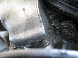
Preventing Cam Oil Seal Leaks from Degrading Your Pump Seal. [Paul Ramdial] I have learnt that the water pump seal can be a victim of an oil leak as the oil runs down from the cam area. The oil drip ends up right on top of water pump seal causing it to fail. Luckily I caught the leak early and what I did was clean the water pump seal area and applied a thin coat of Permatex High temperature silicone rtv gasket maker around the seal (the gray silicone shown in the photo at right).
Water Pump Change on B280 Engine. [Alex Dermedgoglo] See the FAQ file on this engine.
Water Pump Gaskets Won't Seal.
Corrosion. [Editor/Art Benstein] Clean up any corrosion at the heater pipe, the block, and the head prior to installation of the new seals, gasket, and pump. Pay close attention to the pitting that sometimes occurs at the head. Use a mirror and make it real clean and smooth.
Use of RTV vs.Gasket Sealer. The Haynes manual advises to apply RTV sealant to the gasket. I understand RTV is to be used instead of a gasket. Is it absolutely necessary to use some kind of sealant with the gasket? [Response 1:] RTV may be used in lieu of the gasket but there's no real reason to substitute for a real gasket (I find RTV is more prone to leakage). The trick in putting in a new water pump is to adhere the gasket to the PUMP side only and leave the gasket-block interface free of Permatex (or whatever gasket sealant you're using). The gasket itself provides a great seal without adhesive but adhering it to the pump first assures that it won't slip when you're installing it. [Response 2:] I've replace 4 water pumps in over 15 years of Volvo ownership and never used Permetex or RTV on a pump gasket. I have used the gasket alone and nary a leak in the lifetime of the pumps. I insert two bolts to hold the gasket to the pump before mounting. after hand tightening all the bolts lever the pump upwards to allow the head to seal correctly with the rubber donut on top of the pump and torque appropriately. [Response: Dave the Volvo Tech] I use a dab (as in a little dab'l do ya) of wheel bearing grease to lube the hole for the tube/o-ring on the back and smear a little grease on the top seal. If you use a small phillips screwdriver in the bottom hole to pry up and start the bolt in the top hole, start the bolt in the left side, and then start the bottom bolt then tighten all of them before installing the two nuts, you shouldn't have any leaks. I've done a ton of pumps and only had leakers when I damaged the seals/gaskets. Silicone RTV is WAY overrated- as a professional wrench, I can open a tube and it goes bad before I use half of it. Make sure the sealing area of the head where the top seal goes is nice and clean. BTW, I can do a pump on a hot engine in 20 minutes. [Evan] If you feel you need a sealer, use Hylomar HPF (from Permatex, et al) since it stays elastic forever and seals small indentations better.
Re-sealing the Gasket After Installation. [Inquiry] Top of water pump connection gasket seeps anti freeze when overflow tank is filled. Is it possible to loosen and re snug waterpump and 90 degree connector to block cast piece back together or loosen the connection and put permatex on surfaces instead of completely removing pump? [Response] What you propose is not a good idea. You will always have a little drip out of there that will contaminate the RTV (Permatex) It will leak and make your belts squeal. IPS (http://www.importpartsspec.com) just sold me a complete re-seal kit for that application for like $2.50.
Water Pump Line Replacement. Any secrets for hooking the hard water line to the pump? I'm talking about the one that attaches to the block near the coolant draincock, and then runs around behind the block. When I install a water pump, I "lubricate" the seal on that pipe and the opening in the pump with a very thin coating of red RTV. In the 8-10 water pumps I've installed, I've never had a problem, leak, or failure. I'm sure others out there would object to this practice -- but it has worked well for me since my first Volvo, a 1972 142E -- and I'm on my 15th, or so, Volvo. When I say "lubricate" I do NOT really mean lubricate. That is, DO NOT use oil or grease. Let me repeat: DO NOT use oil or grease. The RTV adds a little extra sealing property to the O-ring, and while it's still gooey, it's slippery. I find it helps the O-ring fit and seat properly into the pump. Of course, both the female opening in the pump and the end of the pipe must be clean and dirt-free, and the O-ring must be new. By the way, that pipe carries the hot antifreeze to your heater. Because it bypasses the thermostat, you get heat in the car while the radiator's still cold.
[Editor] Check this line for corrosion at the welded bracket near the manifold. See the Loss of Coolant section below.
Radiators and Components:
Emergency Radiator Repair. [Tip from bl] Here is a temporary radiator fix for you bricksters who manage to break off one of the hose flanges on the crummy, OEM plastic radiators. It's not a matter of if this will happen, only when. Dad broke the upper hose flange off on his 90, 740 last week. Having sold plumbing parts for years, he came up with this fix that works like a charm and will get you back on the road in a few minutes. You need a short piece of 7/8" dishwasher drain hose and a 3/4" copper sweat coupling. Break off the remaining fragments of the hose flange. Take a 3-4" long piece of the dishwasher hose and force it in the hole in the radiator. It's a TIGHT fit but it will go. A little spit helps. When it's inside the rad about an inch, shove the copper coupling inside the drain hose. This just stiffens and expands the hose slightly. Reinstall your rad hose ( it'll be a perfect fit), replace your lost antifreeze and hit the road. Needless to say, this is for emergencies only; you will need a new radiator very quickly.
Radiator Sensor Seal. [Inquiry] The temperature sensor on radiator popped out because the rubber seal loosened. I lost all my coolant. How do I reinstall it? [Response] The seals are supposed to be installed once and replaced when they fail or are removed. OEM seals are imprinted "one use only". Buy the seal at the dealer. Do not use sealer or adhesive while installing, but you need to lube it with a waterbased lubricant such as soap or rubber lube to install. To install, first seat the rubber gasket in the hole, them push in the sensor. It expands the gasket to a tight fit. Buy two seals and carry a spare. Since the seal might have popped out due to overpressure, now is the time to inspect the cooling system for any plugged hoses, failed thermostat, etc. You can use heavy brass wire or a zip tie to secure the plug. Loop the wire around a fin on the radiator (that closest to the front of the engine). Put the wire across the notch in the plug and then under the transmission fluid line. Bring the wire back up toward the fin, and twist three times, to close the loop. This wire will keep the plug from backing-out.
Radiator Plug and Gasket. [Jay Simkin] If your radiator has an extra hole for an unused sensor, the grommet is Volvo p/n 1378869 ($4) and the plug is Volvo p/n 1274052 ($1.75)
B230 Engines.
Brass/Solder Replacement Units. [Editor] In short, don't bother: while you can buy brass/solder construction radiators from Internet suppliers as well as local retailers, it frankly does not make any sense. They are not as reliable as the aluminum/plastic units, nor as efficient in cooling. Often they are sourced from questionable Asian operations. And Volvo coolant and Dexcool tend to eat the solder in these radiators. [Note: See Coolant Recommendations below.] [Comment:] The quality of aftermarket radiators varies considerably. The brand I use in my shop is "Nissens". Nissen All-Metal Radiator Composition. [Tip from A. Sorenson at Nissens.dk] Our solder composition is 33% tin and 77% lead [Editor: thereby qualifying as "low-lead" but still soldered.]
Aluminum/Plastic Replacement Units. The OEM radiator is an AL-reinforced plastic composite and is very light as well as being made of aluminum, which tends not to corrode in the correct coolant. For an exact replacment, buy one at Borton Volvo. For a similar but slightly less robust replacement made by Nissen, buy it from IPD or FCPG. This radiator has a lifetime of about eight years due to side tank embrittlement from heat. Other radiators have been reputed to have fitment problems.
Temperature Sensor Plug. Replacement radiators are generic for both Bosch and Regina-equipped cars. Regina and some Bosch systems use a temperature sensor that fits into a hole in the passenger side tank; it activates the electric fan. When you buy your replacement radiator, make sure you ask for the rubber plug that fills the hole if your system does not use the sensor. If your system uses the sensor, then ask for a new rubber seal to hold the sensor in place. Remove the sensor by pulling it from the gasket. It uses no sealants and relies on a friction fit. To install, first seat the gasket in the hole, them push in the sensor. It expands the gasket to a tight fit. Liquid soap helps. Do not reuse the seal: install a new one if you remove it.
What’s with the sensor hole in aftermarket radiators for the 940’s and why can’t I find a Nissens rad without this hole for a late model base 940 that doesn’t use a sensor? [Response by Dave Stevens] For 940’s with Regina FI (and earlier 740’s) there is a temperature sensor in the top corner of the radiator above the transmission cooler lines. It’s mounted in a rubber insert. This sensor directly controls the electric cooling fan. In the later Bosch FI systems there is no sensor in the rad (fan control is done by the ECU and the A/C presso-stat switch). In aftermarket catalogues you will often see the same radiator listed for all years of non-turbo 940’s. These all come with a hole for the temp sensor. The hole simply needs to be plugged for use with the later systems. As an example, for the popular Nissens rads, there is only a single rad listed for all 1992-1995 base 8-valve (non-turbo) 940’s as p/n 8602563 (replacing Volvo p/n 8602563 and 8601002). This is a 2-row aluminum core rad with plastic side tanks, similar to the Volvo original (reportedly made by Blackstone). As a side note, the often talked about all-metal heavy duty Nissens rad is apparently no longer available as of 2006 (some catalogues are currently out of date on this, although the images are usually correct). Some catalogues do mention Regina/Bosch systems, the rubber insert/adapter and a plug (as options and often with part numbers), but the applications are not usually crystal clear. With the early Nissens rads, you seemingly had to order these items separately. The rubber insert/adapters can still be found (even from Volvo) as they are used with the temp sensor, but the plugs to seal them off may be difficult to find or not in stock. The Nissens rads now come with the rubber insert/adapter -there is no mention of this in the catalogues or on the rad carton. These are in a parts bag hidden under the rad behind a cinched piece of cardboard. When you need to plug the sensor hole, these should be installed dry. RTV or other sealant should not be needed, at least not with a new plug/insert. The rubber insert pushes in easily. The plastic stopper is rough sided and a very tight friction fit to expand the rubber insert and prevent blow out, even under much higher than normal pressure. The plug is virtually impossible to install by hand. The easiest and proper way to install it is to use a press, vise or clamp. Do this before installing the rad. In my case a largish C-clamp with a wood protector on the back side of the plastic tank worked well. If your aftermarket rad happens to come without the plug then the simplest solution is to use a rubber expander plug like the type used in oil pans where the drain plug hole threads are stripped. Use a 3/4" barrel shaped expander plug such as Papco p/n 263548. These are quite cheap and commonly available from your local auto supply house. Mount the plugs flush to the tank face so the rubber will expand behind the hole, locking it in place. Do not over tighten an expansion plug –once the plug is gripping, an extra turn of the nut should be all that’s needed to lock it in place.
Procedure: To remove the radiator:
- remove top support brackets and trim pieces
- remove electric fan and shroud if so equipped
- remove bottom airflow dam beneath the car which is screwed into the bottom of the radiator
- remove automatic transmission coolant lines; not much oil will drain out, so use a cloth under them to catch that which does
- disconnect and remove temperature sensor if installed
- disconnect lower and upper coolant hoses and reservoir hose
- disconnect air hose to reservoir from top left of radiator
- lift radiator out
- remove rubber supports on bottom and transfer to new radiator
- reverse the process for installation
- if your radiator has a coolant temperature sensor, use soapy water to install the rubber seal with the sensor in the middle. Don't throw the box out before making sure you have this seal.
Tips:
- don't overtorque the hose clamps on plastic radiator connections or the coolant line nuts
- use a backup wrench when tightening coolant line nuts
- now is a great time to replace hoses,coolant reservoir, and thermostat
- loosen the thermostat housing nuts to relieve trapped air when refilling
- [Mike Brown/Walt Posluszny] if the transmission cooler lines won't thread, take off the clip that holds the two lines together back near the engine so that you have a little more flexibility in lining up the fittings. Then put a little ATFon the threads to lubricate them and move the trans line around with one hand to orient it 90 degrees to the fitting while screwing in the fitting with your other hand. It takes some patience.
B6304 Engines. [Rafael Riverol] Don't look for an "all-metal" replacement radiator. You do not want an all metal radiator in your 960/90 series car. You want a Volvo (Blackstone OEM) or perhaps Nissens aluminum and plastic radiator to avoid bimetallic corrosion of the engine through any voltage in the coolant, such as from bad grounds. You also want to put in new Volvo coolant mixed 50/50 with distilled water.
 Coolant
Reservoir Replacement . [Tip from Paul Seminara] I have found
the source of disappearing coolant from a 1992 940T. The lower outlet on the
coolant expansion tank is cracked. These rectangular tanks have a steel
insert, presumably to prevent damage due to overtightening. Corrosion of this
inset has lead to swelling and cracking of the plastic. I suggest that
if you find a trace of leaking coolant at this point, you remove the hose and
inspect this and not just tighten the hose clamp.[Brian Sullivan]
My nine-year-old 945T developed a very small crack in the top of the reservoir...
it bubbled a bit when the engine was hot. When I pulled the outlet hose off
the bottom of the old tank, the bottom 1/4" or so of the plastic crumbled and
fell in the hose. Also, one of the interior plastic walls had broken, and a
chunk was floating in the tank. [Editor] These tanks will embrittle over
time and should be changed as a "wear" item. Every eight years, at the
same time as the radiator, is appropriate. Some instances of severe engine overheating have been reported due to cracking of this reservoir. Cleaning the Reservoir. [Gary Smith] To remove deposits and sediment in the reservoir, remove it from the car and use hot water and dishwasher detergent (like electra-sol, not the stuff you
use for doing dishes by hand). Fill it half full with hot water and a
shot of detergent, cover the openings, and shake it up. Let it set for
maybe an hour, then rinse it all out. That should get rid of most of
the crud. [John Sargent] Use muriatic acid. [Chris Stites] Use hop soapy water and a cup of course sand, well shaken.
Coolant
Reservoir Replacement . [Tip from Paul Seminara] I have found
the source of disappearing coolant from a 1992 940T. The lower outlet on the
coolant expansion tank is cracked. These rectangular tanks have a steel
insert, presumably to prevent damage due to overtightening. Corrosion of this
inset has lead to swelling and cracking of the plastic. I suggest that
if you find a trace of leaking coolant at this point, you remove the hose and
inspect this and not just tighten the hose clamp.[Brian Sullivan]
My nine-year-old 945T developed a very small crack in the top of the reservoir...
it bubbled a bit when the engine was hot. When I pulled the outlet hose off
the bottom of the old tank, the bottom 1/4" or so of the plastic crumbled and
fell in the hose. Also, one of the interior plastic walls had broken, and a
chunk was floating in the tank. [Editor] These tanks will embrittle over
time and should be changed as a "wear" item. Every eight years, at the
same time as the radiator, is appropriate. Some instances of severe engine overheating have been reported due to cracking of this reservoir. Cleaning the Reservoir. [Gary Smith] To remove deposits and sediment in the reservoir, remove it from the car and use hot water and dishwasher detergent (like electra-sol, not the stuff you
use for doing dishes by hand). Fill it half full with hot water and a
shot of detergent, cover the openings, and shake it up. Let it set for
maybe an hour, then rinse it all out. That should get rid of most of
the crud. [John Sargent] Use muriatic acid. [Chris Stites] Use hop soapy water and a cup of course sand, well shaken.
Engine Freeze Plugs: We in the great white north (Canada) refer to these casting plugs as "frost plugs"; they are intended to pop in the event that the engine is filled with water rather than anti-freeze and the temperature drops below freezing-they are sacrificial in order to save the block from cracking. The one below plug two is actually removable in order to insert a block heater, in fact these plugs and block heaters both corrode with equal regularity (about once every 150,000-250,000 kms) and fall out causing loss of coolant and if not detected, overheating... a quick and inexpensive repair in either case unless, of course, not detected in time. Keep watching those temp gauges.
Loss of Coolant:
Coolant Loss: How to Diagnose? [Inquiry:] My Brick is losing coolant; is it the head gasket? How do I tell? [Response: Don Foster] Pulling the head is not a casual or inexpensive job and should not be done until you have eliminated all other leak candidates. First, look long and hard for the leak:
- Look for the obvious leaks first. These include:
- Radiator and radiator hoses
- Heater hoses
- Heater water valve
- Water pump and gaskets/o-ring: when the seal starts to leak, often antifreeze can "sneak" unseen down to the splash pan -- and if it's a slowish leak, you might not see a puddle 'til the leak gets worse. The antifreeze will escape only when you're driving.
- Overflow reservoir, including the cap and the pipe at the bottom which corrodes and leaks
- Thermostat housing which can corrode
- Turbos: Coolant hoses to the oil cooler; coolant hoses to the turbo
- Less common leaks:
- Head Gasket. If it were my car and I was worried about disappearing antifreeze, I'd carefully crack the oil drain plug, let the first few tablespoons drip into a bowl, and examine it carefully for antifreeze. It'll sink to the bottom, so should be the first out. Do this with a stone-cold engine (not run for several days). If the antifreeze has mixed with the oil in a running engine, it'll form a "dispersion" and the oil will take on a grayish, cloudy characteristic. Next, I'd pull each sparkplug and look for evidence of coolant in the cylinders. BTW, an engine leaking coolant into a combustion chamber will have an unusual amount of white exhaust smoke, particluarly on a cold day (steam). More typical, however, is that the combustion gasses are forced into the cooling system -- and can be detected with a simple instrument. Every garage should have one. I do. See Head Gasket Failure.
- Heater Core. Another "invisible" (but problematic) leak might be the heater core. Or even the heater control valve. If you find something around the heater (and fix it) don't forget to get the coolant out from under the carpets -- they really should be pulled. Otherwise you'll be facing rusted floors in a year, or so.
- Transmission Oil Cooler. If you have oil in your coolant or coolant in your transmission fluid, the transmission cooler on the right side of the radiator is leaking and must be replaced ASAP.
Cooling System Pressure Test. [Editor] The best way to diagnose cooling system problems is to pressurize the cooling system and look for either visible leaks or pressure drops. You can take the car to a shop with the pressurizing device or make your own. Pressurize the system to 9-12 psi (65-85 kPa) for 1984-86 cars or 22 psi (150 kPa) for 1987+ cars with B2XX engines. The pressure should not noticeably drop within three minutes, else you have a leak. If the leak is internal, you won't necessarily see it. See below for a homemade tester. This way you can accelerate any leak for you inspection without running the engine. [Editor's note: see Headgasket Failure for further notes on a cooling system pressure test: highly recommended that you have the correct equipment for this.]
Sudden Loss of Coolant and Engine Overheating Incidents. [Steve Ringlee] We recently surveyed the Brickboard and Swedishbricks lists for incidents of sudden loss of coolant and engine overheating. Here are the results:
- Plastic-bodied engine-side heater water valve cracked; coolant was pumped out. In most of the incidents, drivers did not notice the loss because the coolant was pumped or blown under the car. In most cases, the first evidence was engine noise, slowing of the car, or other signs of serious engine damage. [Steve Seekins:] These valves crack longitudinally along the plastic center pipe. Note that heater-only equipped cars have a plastic valve inside the car on the left side of the center console. For replacement instructions see the link.
- Heater hose fractured due to aging and internal crack; catastrophic loss of coolant
- Heater hose chaffed against block, rubbing through and failing; catastrophic loss of coolant
- Heater hose was not secured by plastic clip and contacted EGR exhaust tube, melting it and causing a sudden leak
- Water pump-to-heater tube corroded at welded support bracket and failed
- Radiator plastic side tank fractured; catastrophic loss of coolant
- Radiator hose split due to aging and internal crack. Upper: loss of coolant; lower: catastrophic loss of coolant
- Top radiator hose clamp was over-tightened, cracking plastic neck outlet. Some coolant was pumped out and the engine temp gauge showed overheating but no damage occurred.
- Hose clamp failed; lower radiator hose parted from radiator outlet neck. All the coolant suddenly drained out of the radiator, leaving only the coolant in the block. Engine required a new headgasket.
- Turbo oil cooler coolant hose became oil-soaked and failed. Check these when you change your oil filter: they are below and behind the oil filter assembly.
- Coolant reservoir hose became oil-soaked at the clamp and split. All coolant was pumped out and the engine overheated.
- Coolant reservoir bottom nipple broke off, the tank fractured, or the cap leaked, causing loss of coolant.
- Water pump seized due to a bearing failure around the pump shaft, shucking one of the two drive belts. The remaining belt was sufficient to start the pump turning again, but this resulted in the cast iron pump impeller coming into contact with the back of the pump casing, smashing it and causing loss of coolant.
- Electric frost plug engine heater leaked due to corrosion of the anchoring device; slow leak.
- Nobody mentioned a failed water pump shaft seal as a cause of catastrophic loss-of-coolant, merely resulting in slow leaks.
In almost every case, the lack of an "idiot light" caused drivers not to notice the loss until too late. When the driver finally looked at the temperature gauge, it was invariably far into the red zone, indicating serious overheating. In almost every case, drivers attempted to drive to a convenient destination such as home, a gas station, or a freeway exit. This extended drive usually led to further engine damage. The least damage noted (except in the last instance) was head gasket; in many instances the engine required replacement.
Lessons learned:
- Assume that your cooling system components have a limited lifespan. Replace them according to an intelligent schedule. I replace hoses and water valve every eight years and the radiator at year ten. I replace the water pump either at a convenient maintenance interval or when it starts leaking at the seal. For turbo cars, assume that the higher underhood temperatures will reduce component lifetimes, so that your radiator and water valve will last only eight years. Brickboard consensus is that the strong points in the cooling system are the OEM hoses; the weakest point is definitely the heater water valve; and the plastic radiator side tanks are in between.
- Give serious thought to installing a loss-of-coolant sensor and an indicator light wired into your instrument cluster. "I didn't notice until it was too late" was a universal experience.
- If you notice smoke, fluid or other evidence of engine distress, STOP and see what the matter is before trying to go any further. Shut the engine off if you have a loss-of-coolant or oil. All it takes is about one minute of operation with no coolant to fry your head gasket. "I tried to get to a service station" are the last rites for many engines.
- [Rob Bareiss] You should ALWAYS replace the heater control valve (water valve) on any 7/9 series car that has already had an overheating event. A failed water valve is probably the #1 cause of a secondary cooling system failure within 2 weeks after the first has been fixed (i.e. radiator, hose, water pump, etc).
Loss
of Coolant Sensor for Volvo 740/940 Cars: [from Steve Ringlee]
These plans allow you to fabricate and install a low-coolant sensor in your car so that you can detect either slow or sudden coolant leaks and take appropriate action before your engine overheats. Volvo 960 and some 760 cars have these sensors already installed.Volvo 740 and 940 have the indicator position in the instrument panel, but no lamp or sensor (see the photo to the right). Note: Dick Riess contributed a plan for an easier-to-install warning light using a dash switch cutout instead of the panel. See the section at the end below.
Overall Plan.
a) Volvo 740 with Circular Oval Tank.
Using a Nohken normally-open float level sensor switch, drill a hole in the bottom of the coolant tank and install the sensor. One lead is wired to the front grounding plane near the passenger-side headlight, the other back around the engine compartment, through the firewall, to the unused instrument panel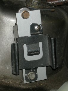 lamp denoted "EGR Overheating (Japan Only)." When coolant is low, the switch closes, allowing 12V from the panel to travel through the switch to ground, illuminating the warning lamp. By the way, this is a great time to replace your coolant reservoir tank, which is at least eight years old and does not last forever.
[John Sargent] You can also obtain, from a wrecking yard, a 960 reservoir with sensor and wiring pre-installed along with its bracket (bring a drill to remove the spot welds holding the old bracket on). You can fabricate a new mount by drilling out the spot welds on the old mount and screwing a flat aluminum plate to hold the 960 reservoir. Install and wire as noted below.
lamp denoted "EGR Overheating (Japan Only)." When coolant is low, the switch closes, allowing 12V from the panel to travel through the switch to ground, illuminating the warning lamp. By the way, this is a great time to replace your coolant reservoir tank, which is at least eight years old and does not last forever.
[John Sargent] You can also obtain, from a wrecking yard, a 960 reservoir with sensor and wiring pre-installed along with its bracket (bring a drill to remove the spot welds holding the old bracket on). You can fabricate a new mount by drilling out the spot welds on the old mount and screwing a flat aluminum plate to hold the 960 reservoir. Install and wire as noted below.
b) Volvo 940 with Rectangular Tank
Volvo may have included a level float in this tank, but not the sensor. Buy a "Level Guard" sensor Volvo p/n 3547710 and wire as noted below. Remove the tank and shake it; if you hear the level float rattling, then it has a float. Check the bottom of the tank for the molded-in words "without float sensor": if you see. these, you need a replacement tank with the float. If you don't have the float, buy a new reservoir p/n 9122997 (around $30). Make sure you read all assembly instructions below first, especially to confirm you have the float inside the tank. There is a "Low Coolant" lamp position already in the row of panel warning lamps.
Bill of Materials:
- 740 Variant: Float Level Sensor Switch:
Nohken LS-11P-0A, miniature 10VA switch (normally open) with polypropylene float,
 temperature
rating above 100 C, and stem and flat flange face. This is known in the trade
as a "liquid level switch".
temperature
rating above 100 C, and stem and flat flange face. This is known in the trade
as a "liquid level switch".
There are two sources: (1) Scientific Technologies Inc. at 6550 Dumbarton Circle, Fremont, CA 94555-3611, 510-608-3400. Order STI part number 22152; cost is approximately $15 plus a fairly hefty shipping charge. Web site is http://www.sti.com (2) Less expensive is the version from McMaster-Carr (part number 50195K74 for $19.55- get the "NO" Normally Open switch)
940 Variant: Volvo "Level Guard" p/n 3547710) approx $15 from Borton's Volvo, http://www.borton.com , FCPGroton, or from a junkyard off a wrecked 960 car. This device resembles a thin tube about three inches long. If you get it from a 960, take the electrical connector as well (the same connector as is on the brake and washer reservoir fluid sensors).
b) Volvo 12v 1.2w lamp for instrument panel: Volvo uses two instrument panels (Yazaki and VDO) and several kinds of bulbs and bulb holders for their panels. One is a replaceable bulb with wire leads, inserted into a holder that has a plastic locking ring. The other is a bulb soldered into a holder with metal locking tabs. You will probably have to pull your panel to determine which make and lamp type your car has. Dealer prices are quite high (~$3-4 per bulb and $5-6 per holder). Examine the bulbs carefully: in some cases, you can find them at Walmart (e.g., Yazaki 158 bulbs or Osram 2721).
- 740 with Yazaki pane:Volvo p/n 2721 1.2w replaceable bulb with leads
- 940 with VDO panel:Volvo p/n 966326-1 1.2w bulb fixed into holder
- 940 with Yazaki panel:Volvo p/n 942327-8 1.2w bulb; Volvo p/n 9128743-3 Lamp socket. You have spares of this socket on your panel in unused slots.
c) Instrument panel female metal electrical connector inserted into "C" harness connector:
- 740 and 940 before 1994: ell-shaped "C" connector uses Volvo p/n 949542 (likewise "L" shaped)
- 940 1994+: flat "C" connector uses flat Volvo p/n 9148152
- You can find these easily at boneyards: pull the panel, cut off the entire "C" harness connector, and re-use the metal connectors inside
d) Electrical Supplies, all from Radio Shack (one each unless noted):
- Insulated Wire: 20 gauge stranded approx 25 feet p/n 278-1225
- Snap Connector 22-18 g, p/n 64-3085
- Quick Disconnect Connector, Female, .25 inch, p/n 64-4040
- Crimp Butt Connector, 22-18 gauge (quantity=2) p/n 64-3037
- Shrink tubing for insulating connections p/n 278-1611
- Option: Piezo buzzer p/n 273-059 (gives audible warning, but realize it will go off with merely cold, low coolant)
- Soldering iron with electronic solder
e) Mechanical Supplies:
- Wire ties for securing wire to existing harnesses
- "OxGard" conductive electrical grease (from hardware store)
- Silicone dielectric insulating grease (from auto parts store)
- Volvo 940 applications: None other required
- Volvo 740 applications: (from hardware store)
- Neoprene O-Ring O.D. 1/2 inch, I.D. 3/8 inch
- Neoprene Flat Washer O.D. 7/8 inch, I.D. 3/8 inch
f) Volvo wiring diagram to understand your panel connectors. Here is where Chilton's will finally choke you, and you will be motivated to buy the OEM wiring diagram which is absolutely the best on the market. Approx. $30 from Volvo NA at Volvo Technical Publications.
Assembly Instructions:
1. Volvo 940:
a) Drain coolant recovery tank and remove from car. Shake the tank to make sure that Volvo installed the magnetic float that activates the Level Guard inside the tank. (It rattles. If you can't hear the rattle, install the Level Guard and test it with a multimeter for resistance change as the tank is filled with water.) If your tank has the float, install the "Level Guard" sensor into the snap hole on the bottom of the tank. Insert the wire leads into the tank's wiring connector holder on the bottom. Continue below at step e).
If you don't have a magnetic float inside, you can either proceed as though you own a 740, or buy a new tank (p/n 9122997) with a float inside from Borton's for about $30. My experience is that the tanks that were installed at the factory in 940s did NOT have the magnetic floats
Volvo 740:
a) Drain coolant recovery tank and remove from car.
b) Drill a 10mm hole on the flat surface of the underside, approximately one inch toward the center from the threaded cap. [Tip by John Sargent] After drilling the hole in the bottom of the coolant reservoir, I used a beveling tool to create a 45 degree shoulder at the start of the hole. The beveling tool has a 90 degree included angle. The purpose of this beveled shoulder is to create a slight recess for the o-ring to seat in. I turned the tool in reverse in my drill. The tool is quite sharp, and is much too hungry to use on plastic in forward rotation.
c) Remove the float and install it so that the switch operates in the "N.O." ("Normally open") position. Test the switch operation with the ohmmeter range on a multimeter: when the float is at the bottom of the switch (corresponding to loss-of-coolant) the switch should close and complete the circuit, reducing resistance from infinite to zero.
d) Remove the fixing nut on the bottom of the coolant sensor switch. Install the flat neoprene washer on the switch. Feed the switch wires through the coolant fill hole, then into the hole you drilled on the bottom of the tank. Pull the switch snug. Install the neoprene o-ring, then the fixing nut. Snug up the nut until the switch is firmly held without possibility of leakage. If your hole was oversize, use silicone RTV to seal the gap between the hole and your o-ring.
e) Cut a piece of wire sufficient to reach the grounding panel just behind the headlight. Using a short piece of shrink tubing and a .25 inch female blade quick connector, crimp the connector onto a stripped end of the wire and add some solder to ensure a long-lasting connection. Shrink the shrink-fit tubing onto it at the crimp to serve as corrosion proofing. Clean off the grounding plane connector, install the blade connector and the wire onto the ground, insulate it with some "Oxgard" conductive grease, then feed the wire up the lamp harness back to the coolant tank. (Maintenance note: this is a good opportunity to clean all your grounds and coat with OxGard to prevent future electrical problems. Don't use OxGard on any other connectors in the car aside from grounds.)
f) Volvo 740: Install a snap connector to one wire of the float switch and the ground wire. Again, solder it. Insulate any exposed wire on the connector with shrink tubing. This connector allows you to disconnect the level sensor easily.
Volvo 940:
Using a razor knife and some pliers, cut down the diameter of two female snap connectors and squeeze them so as to fit very tightly on the Level Guard lead connectors. Install one of these snap connectors onto the stripped lead of the ground wire by firmly crimping it. Place silicone dielectric grease on the connection for corrosion protection and connect the ground wire connector to one of the Level Guard leads. If you are ambitious, buy the un-insulated version of the snap connectors, solder them onto the wire, and insulate with shrink tubing. [Alternative: if you visit a junkyard, cut the coolant sensor or brake/washer fluid sensors connector off a 760, 960 or 90 series car and use this instead.]
g) Cut a long length of wire sufficient in length to travel from the coolant tank, up the wiring harness at the top of the firewall, thence through the firewall rubber wiring conduit behind the driver-side strut tower, thence into the cabin with an excess of length to reach well beyond the panel.
h) Volvo 740:
Strip, crimp, and solder one end of this wire (using a crimp connector) to the other sensor switch wire. Insulate where exposed with shrink tubing and apply silicone dielectric grease to the ends of the connector to prevent corrosion.
Volvo 940: Install the other female snap connector onto the stripped lead of the panel wire by firmly crimping it onto the stripped end. Place silicone dielectric grease on the connection for corrosion protection and connect the ground wire connector to the other Level Guard lead. Again, if you are ambitious, buy the un-insulated version of the snap connector, solder it onto the wire, and insulate with shrink tubing.
i) Snake the other end of the wire up to the firewall harness and to the lower firewall rubber wiring conduit just behind the driver strut tower. Use wire ties where appropriate.
j) Cut off one of the smaller rubber wiring conduits in the lower firewall connector just behind the strut tower. Feed the wire through the conduit into the cabin.
k) Remove the battery negative connector to disable the electrical system. Remove the driver side kickpanel (two plastic body mounts at the top, pull out.) Move both the turn signal and wiper handles down, out of the way. Remove the instrument panel (740: remove plastic fascia plates covering the clock and rheostat knobs, then the two screws holding the panel in place.) (760: See Link.) (940: unclip using the two side slits midway up the sides of the bezel. See link.) Pull the panel straight out and rest it on the steering column.
l) Working from underneath, snake the coolant sensor wire from the back of the firewall wiring conduit up through the panel opening. Keep it away from the hood release mechanism, any sharp metal edges, and the ignition module, using wire ties as needed. 
m) Pull the large 12-position "C" plastic wiring connector out from the rear top center of the panel. This connector is white and roughly "ell" shaped when looked at from the side (but is flat for later 940s.)
n) Confirm with your wiring diagram which connector you will use for the warning lamp. In the 1986 740, this is position number 7, numbered on the connector itself, which is not used for any other purpose. In the 1990 740, this is position 12 on the connector, which connects to the unused "Exhaust Gas Temperature" lamp for Japanese applications. In the 1992-1995 940, this is position 5 or 9 on the connector which connects to the unused "High Engine Temperature" lamp. Check your wiring diagram.
If this does not indicate the correct position, shine a small flashlight through each hole until you find it, then trace the circuit up the back of the instrument cluster to the connector and mark it lightly.
o) Cut the coolant sensor wire, leaving enough to reach well beyond the door opening to wire into the back of the panel. [Tip from John Sargent:] I deleted a fuse from the wiring. The fuse is not needed as the miniature lamp limits the current to the wire in the event of a short circuit. All you will get with a short circuit is an illuminated lamp. After all, the Nokia float switch simply connects the instrument lamp to ground, which is all a shorted wire does.
p) If you want to add a piezo audible buzzer, place it in-line between the fuse and the firewall, again using crimp connectors, solder and shrink tubing. Be very careful about soldering near the interior of the car: use a metal guard or shield to keep hot solder off plastic, fabric or leather components.
q) Install the special ell-shaped or flat Volvo metal wire connector p/n as in the parts list above (p/n 949542 or 9148152) to the end of the fuse wire. While this is crimped in place, you should also add a small amount of solder to secure it.
r) Record the colors and positions of the wires at the "C" connector. Snap open the back of the connector and insert the coolant connector at the correct position. Snap it shut, making sure all the wires go back appropriately.
s) Install the Volvo instrument panel lamp at the appropriate lamp position, again per your wiring diagram. On the 1990 740, the lamp is installed at the second in from the driver's side of the panel, in the unused position. In the 1995 Volvo 940, the lamp is installed at position 8 from the passenger side of the panel. If you are confused, use a flashlight and shine it through the empty lamp receptacle to confirm the position from the front. Just make sure from your wiring diagram that you correlate the lamp position with the wiring position in the "C" connector
t) Re-install the "C" connector. Coil extra wire and install a tie to keep it out of the way, and tape it to a convenient support to eliminate rattling. Re-install the panel.
u) Seal the wire passage through the firewall conduit with silicone caulk.
v) Test the installation.
Volvo 740:
Open the coolant tank and place a pencil on the float so as to depress it to the bottom. Start the car. The lamp should go on. Demonstrate several times to wife and kids what this lamp looks like and what they need to do if it goes on (stop the engine ASAP and investigate.)
Volvo 940:
Using a turkey baster or a siphon, empty the coolant reservoir. Start the car. The lamp should go on. See note above.
Regular Maintenance. Because of the peculiarities of the wiring within the instrument panel, your bulb may not illuminate when you turn the ignition to KPII before starting. Hence, periodically test the installation to make sure that the bulb, the sensor, and the circuit operate correctly by performing test v) above.
[Simpler Design from Dick Riess] I varied the alert light design in the car. Being lazy and not having all the parts I led the wire from the sensor through the wiring area on the passenger side and brought it over to one of the switch knock outs. This is where the electric sunroof switch and rear defrost switches are. I had a vacant knock out which I removed. Drilled a hole in the middle and installed a small 12v panel light from Radio Shack. The wire from the level sensor was soldered to one pigtail. Another wire was soldered to the remaining pigtail and then brought to the switched cigar hot wire. This wire was piggybacked to the wire. Be sure to test before buttoning everything up as polarity on the lights I used is important, i.e., red goes to +, otherwise these lights don't work. The sensor works beautifully. When the engine is cold and levels are low the light will flicker when cornering. A good reminder to check.
Ongoing Testing. At least one report of float failure has occurred, so occasionally test your system by pushing down on the float with a pencil, making sure the warning lamp illuminates, and then allowing the float to return to the surface of the coolant.
Troubleshooting:
Turbo with Oil Cooler Can Next to Oil Filter. [Inquiry:] I own a 1991 740 wagon, 125,000 kms, B230F engine, auto, not driven particularly hard. The problem is this: On Sunday I discovered oil in the radiator expansion bottle. But no oil in the radiator! And no sign of oil (frothy or otherwise) on the dip stick. I have taken the car to the local service station thinking that I have a blown head gasket. This afternoon the mechanic has shown me the dismembered bits. No blown head gasket. He is sending the head for a compression test. So what do you think? [Response: Steve Seekins] On this particular car, the problem is likely the oil cooler. Check at the oil filter housing. I think that your car has a sheet metal oil cooler mounted on the oil filter extension housing just forward of the oil filter. It should have two water lines attached. These have a history of developing leaks - it may simply need to be replaced. You can remove it and perform a pressure test on it. If you have the older style cooler, there will be a cast piece there with OIL lines vice the sheet metal piece with WATER lines. The earlier cooler adapters have no water interface so cannot leak water, but do develop oil leaks from worn O-rings. Editor[For any later model turbo, look to the oil cooler next to the oil filter for any oil leaks. They can corrode.
Non-Turbo. Oil in coolant reservoir. The problem turned out to be a leaking radiator ATF cooler. I replaced the radiator and solved it.
Temp Gauge Acts Oddly: Leaking Headgasket? See Temp Gauge Acts Oddly: Leaking Headgasket?
Heater Core Leaks. See the FAQ section for details. Replacement is covered in this section.
Heater Core/Radiator Repeat Failures: Electrolysis or Head Gasket Leaks.
Electrolysis is the presence of stray voltages in your cooling system. Over time, these will cause corrosion and material breakdown in radiators, heater cores, hoses, and engine components. There are two kinds of electrolysis. The chemical type occurs in all vehicles and is a natural result when coolant flows through a system composed of different types of metals (iron, copper, aluminum or brass). The coolant acts as the conductor through which small amounts of current are transferred between metals in the cooling system. Over the passage of time this very small amount of current (less than 0.3 volts) can cause damage to metal surfaces (especially aluminum). Given enough time, the damage will cause a leak to develop. All coolants contain anticorrosion packages designed to counteract this effect during their service lifetimes. The electrical type of electrolysis is much more destructive and is caused by faulty electrical components that deliver stray current (over 0.3 volts) through the cooling system. This may be caused by a faulty ground or a shorted wire near the cooling system. Stray current introduced into a system this way can be strong enough to cause severe damage very quickly. The only way to prevent damage from this type of electrolysis is to correct this problem at the source by isolating electrical components and testing ground connections.
Electrolysis Failures Due to Faulty Grounds and Electrical Components. [Radiator Reporter August 1998: "Electrolysis Problems Continue to Mount", excerpted] Cooling system electrolysis is becoming a frequent problem. Electrolysis occurs when electrical current routes itself through the engine's coolant in search of electrical ground. Current can be introduced into the cooling system in many ways, but the two most common causes are a poor ground to the radiator's electric cooling fan, or a poor ground from the starter motor and engine block to the battery. Any vehicle with accessories bolted to the radiator support or to a nearby component is also a good candidate for electrolysis. Electrolysis is a fast-acting menace that attacks not only radiators and heaters, but can destroy an entire engine in a mere 20,000 miles. Though a small amount of measurable voltage can be detected in most engine cooling systems, due to reactions between the coolant and cooling system metals, the detected voltage should never exceed a tenth of a volt in vehicles equipped with aluminum engine blocks and/or cylinder heads.A poorly grounded engine and starter motor can zap enough current through the cooling system to blast apart a heater or radiator in a matter of weeks or even days, depending on how often the vehicle is started. A partially grounded electric cooling fan, on the other hand, may only shoot a small percentage of its supply voltage through a cooling system, and the effect may take months to reveal itself. Evidence of electrolysis includes unexplained and/or the recurring pinhole leaks in a radiator or heater. Pinholes may form anywhere along the tubes or tank walls, but damage is often concentrated at tube-to-header joints, or in the tube walls near the center of the core, where the electric cooling fan mounts come in contact with the core. To test for electrolysis, connect the negative probe of a digital D.C. voltmeter to the battery's negative post. Then submerge the meter's positive probe into the coolant at the filler neck. Be sure that the positive probe does not touch any metal. Next, note the meter reading, which should be no more than 0.10 volts
([Ron Davis Radiator] Voltage of zero to .3 is normal in a coolant of cast iron engine. Such an engine will be destroyed with time by .5 volts, and engine manufacturers are reporting .15 volts will destroy an aluminum engine. If a higher voltage is detected, methodically shut off or disconnect one electrical component or accessory at a time while watching the voltmeter. When the voltage reading drops to zero, you've pinpointed the electrical component with the defective or missing ground. If you test for and detect an AC voltage, this is due to static electricity. Since electrolysis might occur only when a certain component is energized, have a helper switch each vehicle component on and off while you observe the voltmeter readings. To check components or accessories that don't have an on/off switch, use a long jumper wire connected to the battery's negative post to provide a temporary ground to each electrical accessory. Ground each component with the jumper wire and watch the meter. If the jumper wire restores a missing or faulty ground, the meter will drop to zero. Be sure to check for intermittent voltage surges generated by the starter during cranking. To do so, watch the meter as you crank the engine. Any jump in voltage during cranking indicates a loose, faulty, or missing engine ground. Any electrical device with a huge current draw, like a starter motor or radiator cooling fan, will chew up a cooling system far faster than a trickle of voltage from a poorly grounded underhood relay or other low-amperage device. One telltale sign of electrolysis and/or electro-chemical corrosion is discoloration of the affected area. Aluminum components usually turn black and pitted, while copper/brass components are likely to develop a blue-green corrosion byproduct. Unfortunately, bad coolant can cause similar discoloration, so a blackened PTR core doesn't always mean electrolysis is to blame, but it should raise the possibility in your mind during diagnosis. [Tip] You can solve the problem for particular components by adding redundant ground wires of 16-gauge copper mounted with hose clamps on the component and a screw to body sheet metal.
Electrolysis Failures Due to Leaking Head Gasket. [From Bob Savasta, Motor Magazine, Nov 2001] If you have repeated heater core or aluminum radiator failures, consider one possible source to be coolant breakdown and electrolysis due to combustion gases from head gasket leaks. The Automotive Engine Rebuilders Association (AERA) just recently put out a bulletin for its member shops alerting them to the possibility of combustion leaks causing higher-than-normal electrical charges in the cooling system. Like the information I provided in my May column, AERA advises its shops to first use a DMM and measure the voltage potential of the coolant. Anything over about 100mV is cause for further investigation, says AERA. [Editor: this is for aluminum engines; anything over 0.30v for cast iron blocks needs further study]. If the integrity of all grounds is sound, fresh coolant has been added and you've still got excess voltage, the association then recommends looking for combustion leaks as a major contributor to the problem.
[Symptom:] My temp gauge started going almost to the red (I always shut the car off to avoid a boil over) and gave readings (now that I think about it) that were generally high and also sporadic. [Diagnosis:] I pulled out my Bentley manual and it was plain as day (consistently high sporadic gauge readings) that it was the voltage regulator. I took out the voltage regulator for the temp gauge cleaned the four contacts and voila...no more "overheating."
Temp Gauge Shows Intermittent Redline.
My temp gauge would almost redline for a couple of days but then be normal for a week or a month and then repeat the symptoms. This doesn't feel like an engine that's over-heating. [Fix:] Try loosening the block gauge temperature sender a quarter turn then tighten. Slight corrosion at the sender's threads may interrupt circuit grounding. Worked for me anyway.
[Inquiry: 1991 740 B230F station wagon. Normally the car can sit for 10 20 or 30 minutes at idle and the temp gauge will stay in the normal spot. However, when I run the A/C the car will over heat even if I'm running at 70 - 80 mph.]
[Response 1:] Before you go any further you should wash out your radiator to clear it of any accumulation of bugs and dirt. Many Volvo radiators are replaced for this reason and it does fix them as a new radiator is obviously clean. It could be a thermostat, bad fan clutch, head gasket problem, etc., etc. but the radiator being obstructed is an easy thing to try. Get your garden hose out and wash from the fan side towards the front of the car. If you see a lot of debris then it is worth the trouble to remove fan and fan shroud and continue to wash but more thoroughly. It helps to use Fantastic or Formula 409 as that will get more dirt off the fins of radiator and condenser.
[Response 2 for B230FT:] If this has the oil cooler that is mounted off to the side, you need to clean it too. Remove one bolt at the top; it sits in a molded rubber fitting. Be careful of the hoses! I found this to be totally clogged when the radiator was cleaned. You can't remove it without disconnecting the hoses and having a mess, but you can get at the nooks and crannies where the crud is. Don't
Coolant Sensor Loose in Replacement Metal Radiator.
[Symptom:] I had a metal radiator installed in my 87 765T and have had nothing but problems trying to get the temp sensor sealed in the tank (uses a rubber grommet). Just started leaking again today. Someone mentioned a screw fitting to hold the sensor, but I have been unable to rind one. I believe my radiator is a Nessen and has threads where the holes is for putting the sensor in.
[Fix:] I did two things when I replaced my oem rad with a metal one. I used a brand new grommet and I pulled a wire tie through the rad and around and across the temp sensor between the two spade connectors (it needs to be a pretty long one.) This will prevent the sensor from popping out, not an unheard of scenario.
[Fix 2:] I recently installed a metal radiator from RPR, I believe it is a Nessen brand, and the temp tensor fitting has a metal screw on 'lid' (with a hole cutout in the top of it) which screws down on the temp gauge after it is pressed into the rubber grommet and keeps it snugged down in it's bung (couldn't help myself). Contact RPR, they may be able to help you find a lid.
Thermostatic Fluid Clutch Fan.
The performance of a thermostatic fan clutch will degrade over time by about 200 rpm a year due to fluid failure inside. Eventually, the fan clutch reaches the point where effective cooling is no longer possible and overheating results, even at highway speeds. Since they are not easily repairable, you throw away the old clutch and install a new one. Symptoms of a defective fan clutch include: oily streaks on clutch housing; play in the clutch bearing (wobbling); freewheeling (a good fan should not turn more than one to one-and-a-half turns if spun by hand); and binding (frozen). Simple tests for the fan clutch: the fan should roar when car is first started cold engine. Within 5 minutes the roar should stop/die down. When radiator warms up, the roar should start again. For the thermostatic one (post ~1980), run engine, hang blanket over grille. If the fan starts to get loud and blow more air before the temperature gauge gets too high, the thermostatic clutch works. To check slippage (at normal engine temperature), Volvo suggests using a strobe light with adjustable frequency. You put a timing mark on the fan with chalk, and figure out the fan speed for a few different engine rpms. The chart of engine vs fan speed is in all the different repair manuals.
To Remove the Fan. The four nuts from the water pump pulley come off, and the two screws that hold the top of the fan shroud get removed. Grab the fan and wiggle the fan ( with the clutch still attached ) and remove the fan and shroud together. Transfer the blades and reinstall.
Tropical Heavy Duty Fan Clutch. [Dave Barton] I live in a area that easily gets over 100 degrees F in the Summer. I wasn't completely confident in trying a new "stock" type fan clutch as I figured it still might not handle the high Southern California summer heat so well, so I decided to try Volvo PN 1357433, the tropical (heavy duty) version of this fan clutch. It's an original Volvo item, made by Aisin. I was pleasantly surprised by the result... it pulls noticeably more air when needed. This clutch is only slightly higher in price than a standard type. Buy it from Dave at Barton Harness.
Electric Cooling Fan Operation.
Electric Main Cooling Fan Basics.
[Dave Stevens] For 900's the two speed electric cooling fan is always controlled by the AC pressure sensor switches whether the ignition is on or off. When the engine is running, the electric cooling fan (low speed and high speed) is primarily controlled by the ECU using the block temp sensor for input. You won't find any fuses at the dash, it's only fuse protected at the battery junction box.For the 700-style system the ECU is not involved, it's a single speed fan directly controlled by a coolant thermal switch (upper passenger side of rad). All it needs is the ignition switch at KPII: when the ignition is off, the fan should not run at all. The 700-style system is fully fuse protected at the dash (typically #7 for the fan motor and #9 for the relay control).
Electric Fan Won't Turn On.
[Symptom:] Engine overheats in 940 while sitting in traffic. I have an electric fan on the front of my radiator. I have never seen it come on - What triggers this fan to come on?
[Diagnosis: Dave Stevens] Before you buy a new fan be sure the fan is the problem. When it's cool out, the engine often needs to be pretty hot for the fan to come on. The engine "will" overheat standing still in traffic if the fan doesn't turn on to keep the water temp cool enough, especially if the A/C is on. First make sure the fan motor has not seized. In 740s and some 940s, there is a thermostat switch on the top of the radiator on the passenger side with two wires attached to it. One wire should have voltage to it at all times (engine running). The other wire goes to the fan. If the one wire is hot touch the two together or carefully short them with a screwdriver and the fan should turn on. If the fan works then you probably need a new thermostat switch. If the fan doesn't turn on and it has a proper ground then you probably need a fan. Or remove the connectors, clean and reconnect them.
In later 940s, the coolant fan is controlled by either the high and low pressure air conditioning sensors on the condensor outlet and the ECU block temp sensor: there is no independent radiator fan sensor. The prime suspect is the fan relay; check this behind the left side headlight first. You can also use the OBD system to test the fan on both low
and high speed. Use Diagnostic Test Mode 3 to cycle the various system
components including the fan -it's one of the last things operated as I
recall. Watch your fingers! The cycle will repeat until stopped. Ref DTM
3 in the 700/900 FAQ Engine OBD Diagnostics Procedures. The ECU controls the fan through the fan relay. There's a pressostat switch on the bottom of the AC condensor that can also activate the fan relay. Apart from swapping in a known good part, you'll need to use a voltmeter at the relay socket and the electric fan connector to verify supply voltage.
Electric Fan Will Not Shut Off.
[Dave Stevens] On the 900's the electric cooling fan is supposed to run after engine shutdown if the engine compartment remains hot. Depending on how hot it is under the hood, this shouldn't last for more than a minute or so (it may be intermittent). There are two pressure sensors together on the bottom end rail of the AC condenser (passenger side, behind the bumper skirt). They're ceramic and look a lot like an injector. One is for low speed fan operation (the greyish one) and the other for high speed fan operation (the brownish one). Note that if the AC system has lost its charge then the fan will not operate after engine shutdown. This shouldn't be allowed to continue as the cooling system pressure can rise, unnecessarily stressing the radiator and enough to vent at the reservoir cap and slowly lower the coolant level. If you can't find these pressure sensors and the owner's manual indicates the fan relay is in the relay tray then you have the earlier 700-style system.
For later 900's, if the fan continues to run forever after engine shutdown then that's normally indicative of a bad (shorted) relay, but there's always a slim chance a pressure sensor switch has failed, a relay control wire is pinched and shorting to a ground wire in the harness or to chassis ground, or a connector is on the wrong pressure switch. The relay control wires are Blue-Black (low speed) and White-Black (high speed) running from the relay to both the ECU and to the AC pressure sensors. Pulling the center connector off the relay will remove the ECU from the equation as well as the pressure sensor switches. This will diagnose a bad relay if the fan continues to run, otherwise start isolating relay control wiring problems including bad pressure sensor switches. Pulling the connectors off the sensor switches will diagnose a bad sensor switch. Make sure neither connector with the above mentioned wire colors has been accidentally connected to the violet colored AC pressure switch on the same rail.
For the 700-style system, if the cooling fan runs at all after shutdown then that's almost certainly a bad relay. For 900's the relay (black, with three connectors going into the bottom) is under the hood on the rad housing near the battery (driver side for turbo's, otherwise passenger side). For early 700's the relay should be leftmost in the front row of the relay tray or later 700s on the passenger strut tower. In all these scenarios we're only talking about a bad relay that's stuck open or internally shorted. A bad relay could also be dead resulting in no cooling fan at all -the dash temp needle will climb into the red zone in such a case.
Diagnosing Radiator Temperature Sensors in 700 and early 900 Models. [Response: Bob] Check the temp sensor in the corner of the radiator(pass side) with an ohm meter. With cold engine it should be open. Sometimes they stick closed. If it's bad, be sure to use a new seal when replacing. [Response: Chris Mullet] If you disconnect the wires at the radiator sensor and the fan stops, then the sensor is bad as Bob described. If it keeps running with the wires disconnected, then it is probably the relay. That relay is one of the two mounted on the forward side of the RH shock tower or in later 940 cars, it is a larger relay mounted behind the left side headlight. The other identical relay on the shock tower is the Radio Suppression Relay which feeds juice to the ignition system.
Auxiliary Electric Fan. [Inquiry] I've had my 1989 740 for a year and just yesterday at the muffler shop, while the car was up on the lift, I peeked in the front end, and lo and behold there, in all its glory was an electric fan in front of the A/C radiator. However it never has turned on, that I know...How do I test it to see if it works?, where is the wiring to the sensor that turns it on? [Response: Abe Crombie] On an 89 740 model that fan is triggered just for overheat by a switch in tank of radiator that turns on relay on strut tower that feeds power to fan. If it is a 760 then the relay can be triggered by the aforementioned switch or by a ground out of air conditioning control unit if the outside temp is over 92 F +/- and you are below 8 MPH and the a/c compressor is engaged. To test the fan, find the switch on right radiator end tank and pull back the rubber sleeves covering wires and short the two terminals together with a small screwdriver. Key must be on. If this doesn't make the fan start then go to the relay and check for power supply on one of the two large gauge wires (one is feed and one is to fan motor, so one should be hot). If power is found then disassemble and inspect for cracked solder in relay and repair as needed.
Electric Fan Conversion. [Procedures and results:] installation in a 87 745 ti:
Selection: I bought a Mr. Gasket high performance electric fan, 16 inch, heavy duty plastic with ring shroud. this was about 95 bucks. I also bought an adjustable thermostat kit for about 25 bucks. It had a name brand, I think Flex-a-lite or Therma-cool, but it was universal in its application. some members suggested getting the fan and related items from a new 92 or newer 7/900 but i did not have the time to investigate and I do not know of any u-pick-it type salvage yards in the New York Area (anyone know of any?? i would love to check one out.) The fan I bought pulls 1900 cfm on 10 amps. Similar options are the Flex-a-lite, or Perma-cool. A high end option is the Spal fan which pulls 2300 cfm on 23 amps and has a thermostat that connects directly to the cylinder head but the cost is higher, 155+55... I don't know if one needs this kind of air pull but your call.
Swap:
- I first slackened the tension of the water pump belt.
- Then I removed the clutch fan. there are four 10 mm nuts. I had to loosen each one before I could pull the fan away from the pulley sufficiently to be able to spin the nuts completely off. remove two screws holding shroud to top of radiator. Off came the fan and shroud.
- I removed the four studs and replaced them with 6 mm x 1.0 bolts, 12 mm length, 10 mm head. with a lock washer, these bolts fit perfectly. If you never removed a stud before, put two nuts on the exposed thread (do not use the original nuts as the flange prevents good wrench grasp). tighten the nuts against each other. then try to remove the inner-most nut. since it is tightened against the other nut, turning it forces the whole stud to turn and spin out.
- Tighten the belt.
- I disconnected the inlet and outlet of the intercooler and the radiator/intercooler hold downs. out came the intercooler.
- Position the fan closest to the middle of the radiator in hope of being able to re-install the oem shroud ( I cannot see how this could hurt). test fit the shroud. if it will work, keep the shroud in place as you install the fan or better yet reinstall the shroud and then the fan. (Once the fan is in place, it is a tough fit to get the shroud back in place.)
- The fan I bought had the four nylon rods with nylon lock washers that push on. they work like a two piece zip-tie. Once one, they cannot come off without breaking them. Position the fan and slide the nylon rods thru the fan holds and through the radiator. slip on the lock washers. Use the rubber gaskets as required to protect the radiator on both sides.. do not over tighten. four snug nylon connectors will hold the fan very well. i used them years ago when i added a tran-cooler to my 72 mustang and it held without a problem. Others have suggested facing a better bracket. Your call.
- Once the fan is in place, re-install the inter cooler, hoses, and radiator hold down brackets.
- Regarding the thermo, my understanding is that there are three main types. One contacts the coolant in the cylinder head or thru the radiator, one is just a probe that extends thru the rad fins, and one (like mine) has a probe that gets inserted into the upper rad. opening, bends around the opening and gets sandwiched between the opening and the rad house. They supplied a rubber gasket that has a grove in it. The gasket goes against the rad. neck, and the copper tube attached to the probe lays in the groove. the gasket makes for a smoother transition around the tube in an effort to prevent a leak around the tube. It also protects the tube as one tightens the hose clamp around the radiator hose and neck. The probe tube is attached to a thermostat which I connected to the radiator rail to the right of the radiator behind the lights above the battery. Mine is an adjustable thermo from 180-240 degs. I am still playing with the setting.
- Wiring: attach the fan ground wire to the thermostat. Get the wires straight, one is for power, one is for ground depending on what direction you want the fan to turn, i.e., puller or pusher. From the thermo connect to any good ground. you have options regarding the power supply.
- Connect to a constant power supply if you want the fan to work regardless of ignition key position. This will allow the fan to continue cooling after you have shut off the car. if you have the thermo set low or it fails, the fan could drain the battery. Or, connect to a power supply that is only powered when the car is running (actually when the key is in the run position...) With either power supplies, use an in-line fuse (I am not sure how one decides the fuse amps to use. maybe a reader can advise)
Other options: include a switch to customize when the fan will or will not work depending on where it is positioned and whether or not it provides its own power supply.
See also Dave Barton's discussion of electric fan conversions in 240 and 740 cars.
[Inquiry] Can I install the 940 electric fan on my turbo 740 in place of the mechanical fan? [John Sargent] There isn't enough room on a turbo 700 series (or 1991 940) to install the electric cooling fan from a 1992+ 940: it is just too thick.
960 B6304 Coolant Loss: Coolant Cap At Fault
[Inquiry:] I'm a little concerned about the accounts of casting porosity in the 6 cyl block or head. This would certainly explain my regular loss of coolant. No external leaks, no WP seal or gasket leaks, heater core seems OK (no smell in car, no coolant in condensate rain) no coolant indications in engine oil or ATF. Runs fine so far. Could it be leaking outboard of the exhaust valves and vaporizing in the manifold? I assume this would kill the cat or O2 sensor after a while. But no white smoke shows. Coolant has to be going somewhere and it is doing so at the rate of about a pint a week. In winter. Perhaps more. This engine would fry and bend like a hot dog if it ever got seriously dry. Any ideas? [Response: Tom Irwin] Relax! The block porosity issue was limited to about the first 10,000 units off the line in model year 1992, only! If it was leaking into the oil, your crankcase would be full of mayonnaise, right? Per chance, Greg, do you have a Grey plastic pressure cap?? Hmm? If so, you need a Green one. My wifes 940 and my 960, each with grey caps, failed within 6 mos. of each other. They tend to get little hairline cracks in the threaded portion. They spittle and sputter and ooze coolant ONLY when at temp. and pressurized. Check it out carefully. FWIW, Stant company is selling the new green Volvo caps for half what the dealer wants, under their own name. Also, you change your coolant right? Volvo Type C blue only? Don't believe the "Perma-Fluid" crap in your manual.
Homemade Cooling System Pressure Tester. Here's what I've rigged up for both pressure testing the cooling system and bleeding the clutch and brakes: I found an old bottle cap that has the same threads as the coolant reservoir. Then I bought $1.00 worth of tank valves and screwed one into it. If you don't have such a cap, then an old coolant reservoir cap should work even better. When I need to use it, I take the gasket out of the coolant reservoir cap and use it in my "pressure cap". I connect a $5.00 bicycle pump (with built in pressure gauge) to the cap and presto. Since the brake reservoir has the same type orifice, it can also be used to pressure bleed the clutch and brakes.
Test specs: 12 psi(85 kPa) for up to 1986 cars; 22 psi (150 kPa) for 1987+ cars with B2XX engines. Pressure should not drop noticeably in three minutes.