
Volvo AW-70 Series Transmission Rebuild PDF
Building Automagics: AW71(/72/L)
We'll start this series off with the OE AW7X unit. Note that performance modifications, separate from rebuilding, are discussed at the end of this file below.
For further reference material, most of the rebuild book is available here:
http://www.pbase.com/kdh51/aw_rebuild_book
Picture #'s correspond to page #'s.
USEFUL PART NUMBERS
Frictions (forward/direct/b1/b2):
part no. size current price(usd)
044710 .078 $2.09
044700 .091 $1.78
044700a230 (High Energy, not red eagle) .091 $1.87
Steels:
044701 .071 $1.81
044711 .078 $2.08
044701-140 .055 $2.63
044701-230 .091 $3.00
044701-051 .020 $2.30
044701-076 .030 $2.37 (not sure what real practical purpose these would provide)
These prices came from consolidated trans parts, gulfport, MS (228-539-1559) and I would assume they're subject to change.
These can be used in conjunction with a rebuild kit, or if you're piecing together your own friction and steel module. Additional part numbers for the remaining clutches and steels (in addition to a bunch of other neat stuff, the red eagle and kolene steel stuff) can be found in the catalogs at altousa.com
Part I of the AW71(72/70/L) rebuild guide: De-mystifying the "magic"
Clearances (per the green book):
Measured between the snap ring and pressure plate
B0 (overdrive brake): .35mm- 1.6mm (or ~.014 to .065)
C1/C2/B1/B2: .3 - 1.2mm (or ~.011 to .047).
See "gotcha's" below for tips before you begin.
A slight discussion about disassembly:
All Aw70/71/72's of pretty much any application, come apart the same way:
You should start by removing the oil pan (have something nearby to catch the oil. These things are *NEVER* empty), set it aside, take note of the contents. if it's just a black "dust", you've probably just cooked out clutch material. if there's metal flakes or shavings in there.. something more sinister has gone on (if you're in a jy, just move on to the next unit at this point)
You will find a couple of tubes running across the front of the case to the valve body, use a screwdriver to gently wiggle these guys up and loose. Set them aside. Next you'll want to remove the 8mm bolts holding the filter on, more atf will come running out when you do this. Set this aside, don't mix the bolts up with others. Now, you'll see a whole bunch of 10mm and 8mm bolts on the valve body.. the 10mm bolts hold the valve body to the case. they are varying lengths, so either make a cardboard template to keep things straight, or leave them in the holes and lift the valve body out as unit with them in place. as you get it loose, pay attention to the kickdown cable attached to the throttle valve spool, remove it, set the valve body aside. you might want to pop the kickdown cable out of the case now, just so it's not in the way later. In addition to another 14 quarts of atf, you'll be looking at the parking brake assembly, the accumulators (more on these later), and a couple of 12mm bolts. These bolts hold the Center support. Go ahead and remove them, set them somewhere where you won't lose them or get them mixed up.
If you're going through and rebuilding the whole unit (that's what this writeup is about, after all), you'll want to put the transmission in park, and take the flange off the output shaft. I believe this is a 30mm nut, although it could be a bolt on earlier model transmissions. Air impact works well for this application.
Next up, remove the 6 bolts for the tail housing, and remove the governor. this is accomplished by removing the 8mm bolt, and the spring clip (start on the short side) set this stuff aside. there should be nothing else back there except a steel plate with 3 philips screws. You can ignore that for the moment (it's just a cover for fluid passages)
turn the transmission around so that you're looking at the bell housing and pump, and you'll see some 17mm bolts and 14mm bolts, and then 12mm bolts on the pump itself. Air tools come in handy here as well, go ahead and knock them all loose. wiggle the bell housing towards you, odds are the whole overdrive unit (and maybe the front clutch) will come off/out with it. if the front clutch does come out, set it aside being careful not to lose the needle bearing on the end of the overdrive shell, or the needle bearing that goes between the front clutch and the direct clutch.
You can probably seperate the overdrive unit from the bellhousing by either pulling on it, or gently tapping on the input shaft with a rubber mallet (once it starts moving, generally it just slides out), and the pump can be tapped out the front with the same method.
Almost there. Set the bell housing aside, won't need that for a while. if the front clutch did not come out of the case with the overdrive unit, go ahead and pull it out now, being careful to not drop/lose the aforementioned needle bearings. Next, the direct clutch should slide out, possibly with the center support cluster. Set these aside for the moment (unless you're just dying to look at what's torn up); and let's get the rear brake and planetaries out. There's a snap ring covering the pressure plate, this is a little tricky to get out, a long flat-head screw driver and a 90 degree pick makes this easy. stick the pick in the hole and pull out, the pressure plate and front planetary set should come out. set em aside, and start pulling out the clutches and steels. try and keep em in order so you know what you're working with on re-assembly.
Now all that's left is the rear planetary and the output shaft(s). There are two 10mm bolts that hold the cover on the parking brake assembly, take these out, and lift the arms up. You should be able to grab the shaft and pull the whole shooting match out of the back and slide it all out. Now you've got the components out, you can start dissembling sub-assemblies and assessing what you need to replace.
Over the years, I have found *in general* the only things that routinely need to be replaced are the piston o-rings, and clutches and steels. I replace the sealing rings as a matter of course, and the thrust washers if need-be (generally if they don't look worn out and are still flexible, they're ok).
When taking the hubs apart, try and keep all the individual parts together, this will make re-assembly easier. Pop the snap ring off the hub, remove the pressure plate (in some of them you can pop the snap ring off, turn the unit upside down, and everything slides out. in others, there is an additional snap ring that serves some sort of function), and the clutches and steels. If you want, you can take note of the clearance before disassembling the clutch, and that should point you to your problem area (although it'll be pretty obvious when you pull the pressure plate off). Getting the pistons out of the hubs can be tricky, and is made easier with a tool:
![[Image: 137702567.jpg]](AW7XRebuild/137702567.jpg)
and use it to compress the spring pack to get the retaining clip off:
![[Image: 137702583.jpg]](AW7XRebuild/137702583.jpg)
Rinse, repeat, and you'll eventually end up with something looking like this:
![[Image: 137578112.jpg]](AW7XRebuild/137578112.jpg)
I will update this post with more pictures when I get sam's aw71 on the bench.
Once you have gotten everything disassembled, you should spend some time cleaning it all up. no sense in spending the time and money to rebuild something, only to have some dirt or old fluid ruin your day. I have a parts washer (harbour freight, $60 when it's on super sale, $120 normally), and then I hit everything with brake parts cleaner. WD-40 on shiny parts or things that may rust (or rub em down with new atf). I would recommend doing this in stages, again, to keep the sub-assemblies together.
Now for the Fun! For this particular rebuild, I just ordered a rebuild kit for an A44D with frictions. If you have determined that your steels are still useable, you can go this way, otherwise you'll probably want to order at least replace the ones that are blued/warped/etc.
Friction module:
![[Image: 137702561.jpg]](AW7XRebuild/137702561.jpg)
Complete with pan of fresh atf. New frictions, and frictions that have been out in the air for a while should be soaked in ATF for a few minutes prior to installation.
Starting from the back and working forward (basically, the reverse of removal), we have the rear piston assembly:
![[Image: 137702562.jpg]](AW7XRebuild/137702562.jpg)
Fortunately, the rebuild kit has sub-components labled individually for ease of identification (And some redundancies). Find the bag for the rear piston/brake (pay attention, there are two with similar names. threw me for a loop), install o-rings in grooves, and assemble the three parts like this:
![[Image: 137702563.jpg]](AW7XRebuild/137702563.jpg)
If you pay attention to the shiny parts, it makes decent sense how the whole thing goes together.
lightly wipe down the o-rings with petroleum jelly (or atf), same with the sealing surfaces in the back of the case, and set the piston assembly down in there like this:
![[Image: 137702565.jpg]](AW7XRebuild/137702565.jpg)
push down on the piston(you can't go too far) until it's all the way down in there, stack the spring pack on top
![[Image: 137702566.jpg]](AW7XRebuild/137702566.jpg)
and get the compression tool you built/bought earlier to compress the spring pack:
![[Image: 137702568.jpg]](AW7XRebuild/137702568.jpg)
install the snap ring:
![[Image: 137702570.jpg]](AW7XRebuild/137702570.jpg)
another peek at it through holes in the case:
![[Image: 137702571.jpg]](AW7XRebuild/137702571.jpg)
All done:
![[Image: 137702572.jpg]](AW7XRebuild/137702572.jpg)
Next up, we'll re-assemble the direct hub (C2):
![[Image: 137702573.jpg]](AW7XRebuild/137702573.jpg)
seals installed on the piston:
![[Image: 137702574.jpg]](AW7XRebuild/137702574.jpg)
![[Image: 137702575.jpg]](AW7XRebuild/137702575.jpg)
more PJ on the piston, and sealing surfaces:
![[Image: 137702576.jpg]](AW7XRebuild/137702576.jpg)
and assembled:
![[Image: 137702577.jpg]](AW7XRebuild/137702577.jpg)
Same tool helps here as well.
Center support assembly:
![[Image: 137702578.jpg]](AW7XRebuild/137702578.jpg)
This is the 'back' side, B2
piston pushed in, springs in place:
![[Image: 137702580.jpg]](AW7XRebuild/137702580.jpg)
and retainer and clip installed:
![[Image: 137702581.jpg]](AW7XRebuild/137702581.jpg)
B1, front half of center support
![[Image: 137702582.jpg]](AW7XRebuild/137702582.jpg)
tool in place, installing the retaining clip:
It is worth noting, that on this particular center support, it uses a full complement of return springs. Some of the older transmissions do not have all of these return springs. Assemble accordingly.
Forward clutch/hub C1:
![[Image: 137702586.jpg]](AW7XRebuild/137702586.jpg)
You can use the tool on this, but have to compress it with c-clamps.
Overdrive Clutch/hub C0:
![[Image: 137702587.jpg]](AW7XRebuild/137702587.jpg)
Overdrive overhaul (lol):
overdrive unit with OD clutches removed:
![[Image: 137702589.jpg]](AW7XRebuild/137702589.jpg)
pop the snap ring out (not very difficult, not much pre-load on this spring retainer:
![[Image: 137702590.jpg]](AW7XRebuild/137702590.jpg)
pull the piston out (I used some channel locks, GENTLY!):
![[Image: 137702591.jpg]](AW7XRebuild/137702591.jpg)
clean it all up, put new seals on same as the rest, and re-install:
![[Image: 137702592.jpg]](AW7XRebuild/137702592.jpg)
I found it easier to have the snap ring only halfway stuffed in there vs having it resting just outside the groove, it didn't seem to want to expand into the ring groove when it was fully compressed. after inserting it, go back around it with a screwdriver and make sure it's fully seated in the groove.
In most cases, overdrive will be fine (unless you were beating on the car in OD, in which case, well, you'll have to measure stuff out for that)
the order of assembly for clutch packs, is steel clutch steel clutch steel (or some variation there of depending on count). This one, and a couple others, has a spring steel in it:
![[Image: 137702593.jpg]](AW7XRebuild/137702593.jpg)
It helps cushion engagement.
then a normal steel
![[Image: 137702594.jpg]](AW7XRebuild/137702594.jpg)
and so on until you're done:
![[Image: 137702595.jpg]](AW7XRebuild/137702595.jpg)
set that guy aside for a little while, now it's time to stuff things back in the case!
![[Image: 137702601.jpg]](AW7XRebuild/137702601.jpg)
Make sure on the output shaft to replace the sealing rings, ensure the bearing race for the rear most needle bearing is correctly located in the case (it fits over the lip at the back), and don't forget to wipe some PJ on the steel thrust washer pictured above.
![[Image: 137702602.jpg]](AW7XRebuild/137702602.jpg)
new sealing rings wiped down with PJ.
the "shell" that came out earlier goes over this assembly, and has four tabs that seat it in the lip of the rear piston (the shell is, in effect, an extension of the rear piston). There is a locating tab on the shell, that slides in underneath the rear parking brake bracket bolt hole:
![[Image: 137702603.jpg]](AW7XRebuild/137702603.jpg)
make sure the shell stays flush up against the rear piston, otherwise you'll have issues with the B3 installation.
Which I don't have pictures of. it was kind of a bitch, but maybe I can save some of that for others: once you have the rear planetary set/output shaft stuffed in the case, it's time to start installing B3. the bottom most steel is unique, has a recess that allows it to basically center the shell and retain it. this obviously goes in first. then alternate clutch/steel for a count of 5 (unless you removed more or less). Now comes the real F in the A. The front planetary set you removed earlier(likely attached to the pressure plate being held in with the snap ring), comes off of the pressure plate. pull up, should slide right off. install this, with a new plastic thrust washer facing the steel one we just talked about, first. wiggle/twist/shake/roll the planetary set in, turning the output shaft to ensure the planets seat in with the upper ring gear. It's fully seated when there's very little (1/4 to maybe 1/2 inch) of the assembly protruding from the clutches. you have to spin the pressure plate on so that it will engage the one-way clutch. Counter clockwise. the tab with the piece missing (on mine at least) ended up straight down.
end result looks like this:
![[Image: 137702604.jpg]](AW7XRebuild/137702604.jpg)
on to the center support:
![[Image: 137702598.jpg]](AW7XRebuild/137702598.jpg)
all stacks back together (recessed part of the one way points towards B2 iirc)
![[Image: 137702599.jpg]](AW7XRebuild/137702599.jpg)
and then install the snap ring on top. that is about the normal amount of "free play" pictured.
Stack your clutches and steels in, check clearance per the first post (tighter is normally better to a point)
![[Image: 137702605.jpg]](AW7XRebuild/137702605.jpg)
Stack the clutches and steels in for B1, check your clearances there, and now it's ready to slide it in the case. spin things around a little bit to get it to drop all the way in, make sure it drops down all the way, and spin the center support around til the bolt holes line up. start the bolts, then make sure your fluid passages line up as best possible:
![[Image: 137702609.jpg]](AW7XRebuild/137702609.jpg)
You should end up with it looking back up at you like this:
![[Image: 137702610.jpg]](AW7XRebuild/137702610.jpg)
next, put your clutches in the direct hub, paying attention to clearances again (mine had 3. more on this later). Then, slide it down onto the center support assembly:
![[Image: 137702612.jpg]](AW7XRebuild/137702612.jpg)
Note the bearing race sitting on top.
You should have about this much clearance when it's all the way down:
![[Image: 137702614.jpg]](AW7XRebuild/137702614.jpg)
Assemble C1, there's not really a measureable spec for this, you want to be able to turn the hub somewhat easily (i.e. make sure it's not locked up), and you could probably check clearance on the smaller internal snap ring if you felt the need.
![[Image: 137702611.jpg]](AW7XRebuild/137702611.jpg)
installed:
![[Image: 137702616.jpg]](AW7XRebuild/137702616.jpg)
and another view of how far it needs to be in to be 'in'
![[Image: 137702623.jpg]](AW7XRebuild/137702623.jpg)
next goes the overdrive unit:
![[Image: 137702625.jpg]](AW7XRebuild/137702625.jpg)
line the bolt holes up, don't forget to replace the sealing rings on the back side of the overdrive unit, and don't leave the needle bearing out (otherwise your forward clearance will go cleanly to hell and the shit will probably destroy itself in about 4 minutes)
set the OD planetary set down on it:
![[Image: 137702627.jpg]](AW7XRebuild/137702627.jpg)
assemble C0
![[Image: 137702629.jpg]](AW7XRebuild/137702629.jpg)
set it down on the OD planetary set, making sure to spin it all the way down (And engage the overdrive brake teeth)
![[Image: 137702631.jpg]](AW7XRebuild/137702631.jpg)
put the thinner of the two large O-rings down on the od unit, slide it to the bottom by the case, grab your bellhousing, wipe it down with PJ, and slide it down over the OD unit (should go together a lot easier than it came apart if you cleaned everything up well)
![[Image: 137702635.jpg]](AW7XRebuild/137702635.jpg)
bolt it down
![[Image: 137702639.jpg]](AW7XRebuild/137702639.jpg)
Use the thicker of the two large orings on the pump, line the bolt holes up, and slide it on down (make sure you get the needle bearing installed there)
![[Image: 137702641.jpg]](AW7XRebuild/137702641.jpg)
and you're left with something like this:
![[Image: 137702643.jpg]](AW7XRebuild/137702643.jpg)
(shown with parking brake re-installed)
Ok, demystifying the valve body. A few preliminary words for the un-initiated: This is where the 'magic' happens. the Valve body is the 'ecu' of the transmission (And in later electronically controlled transmissions, you will find that a valve body really isn't much more than a couple fluid paths controlled by solenoids). A lot of stuff goes on in here, there's few simple "drill this, block that, and win" scenarios.. What I mean by this is almost anything you do will have an affect on something else. A trade off, if you will, either in terms of "drive quality" or unexpected behavior.. If you're not sure what you're messing with, odds are you probably shouldn't mess with it. I can speak from first hand knowledge that even one or two seemingly 'straight forward' mods can result in a transmission that goes tango uniform in a single low speed drive around the block (to the point where it barely made it home on top of that), So proceed with caution on undocumented/tested modifications.
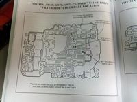
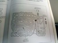
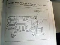
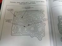
Checkball locations, from the manual: click on the thumbnails for the larger pages.
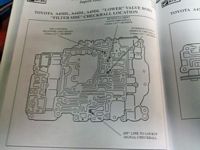
AW71-L (A43DL) valve body, as seen from the pan-side
![[Image: 137808510.jpg]](AW7XRebuild/137808510.jpg)
Pay attention to the shape of the filter, as well as the plate that bolts on (semi-boomerang shaped). this is what a lockup valve body looks like.
Apparently I don't have a better picture of a non-lockup valve body, but this should suffice:
![[Image: 101691438.jpg]](AW7XRebuild/101691438.jpg)
You can see the different casting, the non-wrap around-ness of the top plate, and as a result of the different casting, a missing valve off the top side.
I mentioned cardboard cutouts earlier, this is what I did to keep the bolts straight:
![[Image: 137808511.jpg]](AW7XRebuild/137808511.jpg)
Let's start taking it apart for cleaning:
![[Image: 137808513.jpg]](AW7XRebuild/137808513.jpg)
Note the two check balls, one above the screw driver, and one below. There are three additional ones (pic later when it's more obvious)
Also note the gaskets came off in one piece. If you're careful, the gaskets won't tear, they can be hosed off with brake cleaner and re-used (if your rebuild kit doesn't have all the correct ones, like mine)
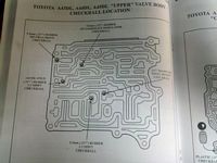
This is the "upper rear valve body". Most of your shift valves reside in this guy. There are between 4 and 5 checkballs located in this little guy
![[Image: 137808519.jpg]](AW7XRebuild/137808519.jpg)
There are bolts that hold this guy on from both sides, that's part of the reason you take the cover off the bottom first. In addition to two long bolts there, there are a couple that reside in the filter area, as well as at least one that hangs out around the rooster comb spring.
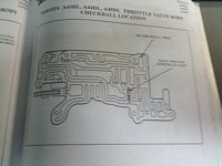
Apparently I didn't take pictures of the throttle valve assembly (or they went missing) as it comes off. get any bolts that hold it on via the filter side first, so you can remove it and not drop the springs and checkballs out of the lower valve body
You might notice a tab and a clip fall out, those locations will be shown later.
![[Image: 137808524.jpg]](AW7XRebuild/137808524.jpg)
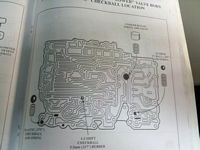
Here's the lower valve body, important locations of things to follow:
![[Image: 137808525.jpg]](AW7XRebuild/137808525.jpg)
The lone free checkball in mine
this guy goes over in this corner:
![[Image: 137808526.jpg]](AW7XRebuild/137808526.jpg)
and the check ball on a spring:
![[Image: 137808527.jpg]](AW7XRebuild/137808527.jpg)
pretty obvious where the cooler bypass pressure setup goes, but here it is regardless:
![[Image: 137808528.jpg]](AW7XRebuild/137808528.jpg)
Here are your upper rear component locations in order of removal:
![[Image: 137808532.jpg]](AW7XRebuild/137808532.jpg)
The valve body is positioned correctly as well. There is an additional valve on the end, that didn't fit in the picture with the valve body (orientation remains the same)
![[Image: 137808533.jpg]](AW7XRebuild/137808533.jpg)
This is the main valve body, disassembled:
![[Image: 137808538.jpg]](AW7XRebuild/137808538.jpg)
Picture is for reference mainly, as it has a lot of stuff in it.
still didn't want to fit all the way on one paper towel
![[Image: 137808541.jpg]](AW7XRebuild/137808541.jpg)
lockup changeover valve:
![[Image: 137808540.jpg]](AW7XRebuild/137808540.jpg)
Note orientations of various components:
![[Image: 137808542.jpg]](AW7XRebuild/137808542.jpg)
In general, this will be kinda obvious when you go to re-assemble it, stuff either won't fit correctly or you can't put the stops back in correctly, that sort of thing
more stops and little bits
![[Image: 137808543.jpg]](AW7XRebuild/137808543.jpg)
Throttle valve assembly components:
![[Image: 137808545.jpg]](AW7XRebuild/137808545.jpg)
Cut back valve on the left, throttle valve in the middle, and some other shit on the right. Make sure you put the clip underneath the spring on the throttle valve when putting it back together, the spring will drop into the casting otherwise.
Cleaned up separator plate, with a closeup of the C2 feed hole from upper to lower
![[Image: 137808547.jpg]](AW7XRebuild/137808547.jpg)
I believe that's after I drilled it out from ~.092 to ~.125
Shift valve assembly put back together, with check balls (heh, I think I got em all back in there right ![]() )
)
![[Image: 137808548.jpg]](AW7XRebuild/137808548.jpg)
A word about something else not pictured, you'll want to bolt the separator plate to the lower valve body unit using one of the short 8mm bolts, preferably as close to the big pressure relief spring as possible (since that is what will keep it from sitting tight while you position things. As you might have thought.. its not easy getting stuff on there with check-balls in place unless you slather them up with PJ, which is acceptable, I just didn't for the purpose of documentation)
![[Image: 137808553.jpg]](AW7XRebuild/137808553.jpg)
You should be able to see the 5 purple check balls floating around
The upper rear(shift valve) body is already bolted from the back side, you might give yourself a little slack in those bolts so the long ones from the filter side thread up easier.
show-casing cleaned used gaskets
![[Image: 137808554.jpg]](AW7XRebuild/137808554.jpg)
And with the throttle valve bolted on:
![[Image: 137808555.jpg]](AW7XRebuild/137808555.jpg)
All done. You may have noticed that I do not have gaskets on the separator plate.. This is a matter of personal preference as well as using what's available. I didn't actually get the right VB gaskets with the rebuild kit (wtf), and I plan to use the gaskets themselves in a fluid-flow study since they have a nice blueprint of where stuff is and isn't. You can do it either way, I have run valve bodies in the past with no gaskets just fine.
Dirty accumulators:
![[Image: 137808556.jpg]](AW7XRebuild/137808556.jpg)
I have set up the stops in mine to allow for a slight bit of play before stopping. This is a personal preference thing. the brake accumulator and C1 accumulator probably don't have much of a noticeable affect on anything, but shimming C2's accumulator will have a profound impact on park-reverse quality (in short, it's going to 'slam' into gear). At the moment, this is a tradeoff. I will see if I can work around this to still get a nice quality 2-3 shift without the sacrifice of reverse. For the moment, suck it up.
also note the accumulators are in no particular order. they won't fit in the wrong bore, so they're kinda hard to goof up. if you have trouble getting them out on the bench, you can apply air to the bleed-offs in the case. put a rag over them though, it's very messy and airborne accumulators hurt.
Transfer tube locations. the big tube is for the forward clutch (C1)
![[Image: 137808557.jpg]](AW7XRebuild/137808557.jpg)
the small one is for the overdrive brake. If someone was creative enough, a 3 way valve(switch it to full line pressure vs 'normal function') could feasibly be used here to fashion up a transbrake, but I suspect you would be in the transmission A LOT replacing burned up overdrive brake clutches
![[Image: 137808558.jpg]](AW7XRebuild/137808558.jpg)
Oh and be sure to use the two gaskets on the filter, there are passages in there that don't need to be bled over.
Governor re-installed on the tailshaft
![[Image: 137808559.jpg]](AW7XRebuild/137808559.jpg)
tailshaft housing bolted on
![[Image: 137808560.jpg]](AW7XRebuild/137808560.jpg)
Pan on, new pump seal, done:
![[Image: 137808561.jpg]](AW7XRebuild/137808561.jpg)
I am missing some pictures, not sure what happened. My phone is a piece of shit apparently. Component locations for the shift valve body should be in the AW rebuild guide referenced in the first post.
Performance stuff:
We need to think about and determine if and where more clutches should be installed.
The "AW372/KM148" C2 hub and center support pictured above in the rebuild photos. It is actually an A44D setup.
This has a higher capacity B1 setup and deeper tangs on C2 to make use of that, and if it is actually needed or not. Looking through the powerflow (see post below), I don't know that additional B1 clutches will assist with much. It is something they do in the "heavy duty" versions of the transmission, but that may be for help with engine braking in a towing application; not something of overt concern in a performance application (kinda like the second band in a th400, depending on how you set things up you can take it or leave it)
Gotcha's
As with anything, there are things that can and will go wrong, esp if you're swapping out transmissions and not rebuilding the one from the car. I'll update this as stories come in/I goof things up myself
1) a Non lockup converter *will* fit a lockup transmission. But it will not fit correctly, and will feel like it's dragging.
2) exercise a degree of restraint with the trans cooler fittings on the side of the case, they will pull the threads out if you're not careful
3) if something doesn't look quite right or feel quite right, it's probably not right. take it back out and re-check everything. frictions are thin, if a drum gets caught up on the bottom friction (which is going to be the one they hang up on, btw) and you don't catch it, a number of bad things can happen.
principle of operation (background info to help drive discussion and performance)
when not in overdrive, C0 locks the planet carrier to the input shaft. This remains the case in 1st, 2nd, 3rd. Power transmission actually goes through the front freewheel, the clutch allows engine braking (which would otherwise attempt to spin the freewheel backwards where it doesn't lock)
![[Image: 137715526.jpg]](AW7XRebuild/137715526.jpg)
Power flow through the AW7X transmissions:
1st gear, shifter in D:
C0 is locked
C1 is locked
In Manual 1st (shifter in 1), it also applies B3 to allow for engine braking.
2nd Gear, shifter in D:
C0 is locked
C1 is locked
B2 is locked (engages on the shift)
In manual 2nd, it also applies B1 to allow for engine braking (this is the only time B1 gets applied, so.. is it really necessary to have additional clutches there?)
3rd Gear, shifter in D:
C0 is locked
C1 is locked
C2 is locked (engages on the shift)
B2 is also engaged to allow faster downshifting.
Overdrive:
B0 is locked
C1 is locked
C2 is locked
B2 remains locked for the same reasons above.
Performance Mods, current and theoretical:
Of course, everyone (including me) wants to know what to do to get em to hold more power. We'll kick this off with the few current mods available, and go from there to some more theoretical/whiteboard mods, to wishlist mods.
1) Accumulator mod. This really needs no discussion, but here's the reader's digest: The accumulators in the aw7x are "shock absorbers" for the shift circuits they sit on. The mod is to take some round stock (or appropriately sized bolts) to restrict the travel of the piston so more fluid gets to the clutch sooner. You can see what and why in the post above.
2) "Valve body mod". This could be construed as a shift kit of sorts, if you've ever played with a th350 or 400, then you know kinda what you're in for here. This is still a bit of a grey area, however, drilling out the C2 feed does make for a bit of a firmer shift. I stepped mine up from .092 (stock) to about .125, and left the check ball in the circuit. Some people toss the check ball, others recommend drilling out C1 as well. I haven't seen nearly as much carnage on C1 as on C2, so I'm not in as big a rush to work it over.
level 10 vb changes(prelim/rehash):
c2 seperator plate drilled out to approx ~.150
c1 feed appears to be drilled out, but I did not verify this.
![[Image: 137865556.jpg]](AW7XRebuild/137865556.jpg)
took another look at the old level 10 valve body I acquired (actually, borrowed from mike brown). It's an older valve body, but most of the stuff is the same/close enough (or it could be an old aw70/a42 valve body). Anyway, on to the throttle valve changes, since this ties well into this and the paragraph below dealing with constant pressure..
They locked the cutback valve all the way in one direction. without monitoring line pressure in real time, I don't know exactly what the end-result of this mod is, other than it caused... bizarre behavior by itself when I tried it a few years ago, felt like... extreme slip or a reaalllly loose converter. I wouldn't recommend this without some means of measuring opperating pressures. the function of the cutback valve is "to reduce the throttle pressure, and, as a result, the line pressure at normal and high speeds. this allows for less drag via pressure on the pump, and improved quality of shifting". Something we should probably look in to.
The throttle valve spring has a shim on it and it appears there is a notch ground out of part of the throttle valve (pic later). I say appears only since I can't verify at the moment if it is or not. the end-result looks to be a rapid increase in throttle pressure with minimal increase in actual kick-down tension(i.e. lower throttle angle). These two changes could very well be worth looking in to, if the side-effects can be mitigated (in addition to my own modifications causing errant behavior, mike noted that the transmission would shift poorly or not at all before warming up, and may or may not have had late shifts, i.e. bouncing off the rev limiter, then shifting).
**after disassembling and cleaning sam's valve body last night (trans wasn't shifting correctly, probably a sticking kickdown cable as it turns out), there is no new notch ground in on the level 10 throttle valve, the notch appears to be an OE thing (at least in later transmissions).
Semi-theoretical
3) additional clutches. This is a bit of a grey area for a couple of reasons. There is space in C2 to make this mod work (You'd want a selection of .080 and .092 frictions, and you'd want a bunch of the .055 steels in addition to the 'stock' steels), but there is a question as to whether or not this would actually make the pack stronger.. I say that because thinner steels warp faster which would lead to much faster destruction of the stack. Neverless, this is a mod that will probably be tried out on sam's transmission, provided the thin steels can be located in sufficient quantities. Then there's the topic of frictions, aftermarket vs OE. May decide to try out some higher energy frictions in C2 as well, all depends.
4 clutch C2 is 'solved', I have(had, now. the new components have been bagged) bench tested this and found a combination that works with the correct clearances. The question now becomes locating the correct pressure plate in quantity (i.e. without the hassle of raiding toyotas in the junkyard).
What works:
4 of the thinner frictions, .080
3 .055 steels
1 .068 (i think. might be .070) steel, bottom.
.098 pressure plate (vs the .135 that's "stock")
Based on the hit marks on the C1 pressure plate, there was sufficient space to go down and up.
Again, this could yield a shorter shelf life (as any kind of slippage during engagement would be much more likely to warp the steels and thus clearance out the pack) but *should* yield a stronger 3rd gear by adding 33% more clutch surface area.
![[Image: 138444041.jpg]](AW7XRebuild/138444041.jpg)
Constant pressure/manual valve body, and beyond.. not sure how feasible something like this is.. the MVB, might be easier than the other as I would imagine we can grab the 'plug' off an electronic transmission (or plug passages, whichever), but the idea here is somewhat simple: It would be nice to take line pressure out of the equation for the kickdown circuit-because, as we all know, boost and torque output are not directly tied to throttle angle (i.e. you can be making a boatload of tq and boost at 1/2 throttle, and the transmission is going to be running at reduced line pressure). The potential issue, and I'll talk more about this after I re-retrieve the green book @ lunch, is there seem to be 3 different pressures that govern how and where the transmission shifts: you have base line pressure, which gets converted into governor pressure, then you have throttle pressure which stems from the kickdown cable position. Now if we lock throttle pressure (by plugging a passage, moving a valve, whatever) then we have effectively told the transmission "we're at wide open throttle, so hold those shifts til whatever rpm", generally above 5500-6000. This would not make for a pleasant drive to the grocery store. By the same token, if we block off the governor, then we pretty much are forced to manually shift the transmission (if it does anything at all. the lack of governor pressure, or perhaps looping it, could cause a number of other issues). While that might be nice for race conditions (and will probably at some point be tried out), that's not the ultimate goal.
There is also the simple fact that the components in this transmission are just not big enough past a certain point, so the question starts to become "when do you say enough is enough"? I still want to know some of this just to satisfy my own personal curiosity, and surely the most effective way to achieve that goal will be to build some kind of test stand. talks are already under way with the other part of the heebspeed contingent.