
Transmission. Automatic AW70 and ZF
Transmission:Automatic PDF
Maintenance:
A/T Fluid Needs Changing; Late or Poor Shift Quality
Transmission Mount Replacement
Transmission Line Crack Prevention
Transmission Model Information
Non-turbo Transmission in Turbo Car?
Troubleshooting:
Park-Reverse Lockout Button Repair
Transmission Not Shifting Out of Park
Reverse Lights Not Working: Backup Light/Neutral Safety Switch
Removing Shifter Knob and Overdrive Switch
Shift Indicator Lamp Replacement
Auto Tranny Refuses to Reverse: Mount Replacement
Transmission Output Shaft Bushing
Seal Leakage in AW70L Transmission
Overdrive Relay and Function:
AW-70/71 Overdrive Problems: Relay, Switch
AW 70/71 Overdrive Problems: Wiring to Solenoid, Solenoid
Lockup Torque Converter Function for Turbos?
ZF-22:
ZF22 Damage in Park During Smog Test
AW30/40:
Transmission Removal:
Torque Converter Alignment on Transmission Reinstallation
Rebuild Information:
Transmission Rebuilding Instructions: Valve Body and Complete Transmission
AW Transmission Parts and Rebuild Technical Help
Note: This file describes generic procedures and those specific to AW70 and ZF series transmissions found in Volvo 7XX and 940 four-cylinder and PRV-6 cars. For information about the 960/90 series AW-30 electronic transmissions see the separate FAQ file.
Maintenance:
Transmission Service Procedures .
Checking the Fluid Level. To check the transmission fluid level:
- The engine and transmission must be hot (so drive the car for 20 minutes or so)
- The car must be parked on level ground with the handbrake on.
- The engine must be on.
- Start in P, then cycle through all the gears, ending up in P.
- Then check the fluid level at the yellow dipstick. Reinsert the dipstick with the notches toward the rear to avoid jamming it in the tube.
Checking Level When Fluid Is Cold. [Ken C] I've found that when I have the ATF level correct (based on a warmed up transmission and the proper dipstick scale for the temperature), there is also a way to reliably confirm proper fluid level when the engine is stone cold and not running....e.g., after you've let the car sit overnight. On the dipstick, above the plastic part that has the two temperature-specific scales, there is a little rectangular notch on the metal portion. Assuming the fluid level is correct, and the car is stone cold and you haven't started the engine yet, if you withdraw the dipstick and wipe it off and then reinsert it, then upon withdrawing it for this second time the fluid level should be on that notch. This does NOT work if you just withdraw the dipstick and look at it -- you MUST withdraw it, wipe it off, and then reinsert it before withdrawing again to read the level.
Service Procedures. [Inquiry] I am considering doing the 20k transmission service. What do I need to be aware of?
[Editor] Easy: just unscrew the tranny pan drain bolt, drain, and refill with the same quantity to the correct mark on the dipstick. You will need a funnel with a long, thin neck to fit into the drain tube, and a drain pan. Use a socket on a breaker bar (12 inches or longer) to break free the pan bolt, which may have a little corrosion. Be gentle putting it back.
[Response: Chris Herbst] Volvo no longer recommends dropping the pan and cleaning the screen on the AW70 as a matter of routine maintenance, even though there is a strainer in the transmission. Neither it nor the pan need to be cleaned unless major problems have arisen. This is from a recent Volvo Tech Service Bulletin that dropped the recommendation, still found in most owner's manuals. You do still need to drain and refill the pan regularly, though. [Editor] Many owners highly recommend a fluid flush on a periodic basis, say every 60-80k miles. This removes all residual dirt in the fluid.
Drain Plug. Watch out putting the transmission drain plug back in: recommended torque is only 13-17 ft-lb in this soft pan. . The pan is very soft and I stripped the last one that I did. Also use a new aluminum washer if possible. Bolt size is 10mm by 1.50mm thread pitch.
Fluid Specifications and Drain Intervals. Use Dexron fluid in your AW or ZF transmission. The latest Dexron Spec is III-H and it is all backward compatible to the Dexron II or III listed in your owners manual. Even better: buy a synthetic fluid such as Mobil 1. In the Lubrizol knowledge Base site at www.lubrizol.com, they note that two European commercial vehicle automatic transmission makers have posted specs for mineral oil versus Group III hydrocracked and full synthetic automatic transmission fluid lifetimes:
| Transmission Maker | Drain Interval using Mineral Oil Fluid | Drain Interval using Group III Synthetic | Drain Interval using Full Synthetic |
| Voith | 60k km/ 40k miles | 60k km/40k miles | 120k km/80k miles |
| ZF | 30k km/20k miles | 60k km/40k miles | 120k km/80k miles |
This is an indication of the value of synthetics in normal use. Mobil 1 ATF is a full synthetic meeting Dexron III specs. Castrol Syntec is a Group III hydrocracked fluid meeting Dexron III specs.
Safety While Working on Transmission. [Editor] Note that you can accidentally shift your transmission while working around the linkage beneath. To be safe, don't rely on "park": use jack stands and chocks to hold the car secure.
Any Bands to Adjust? [Inquiry:] I recently acquired a Volvo with an AW-70 in good condition from my brother-in-law. I am planning to flush the ATF and replace the filter in the near future. My friend suggested adjusting the bands while I have pan off. Is this a reasonable thing to do? Does the AW70 even have adjustable bands?
[Response: Abe Crombie] The AW55/70/71/72 and BW55 don't have bands. These gearboxes use friction discs as brakes. Disc brakes don't require (nor is there any way for) adjustment.
In-Line Filters. I've had one for a year and due for a replacement and surgery next year. But my unit is made by Tekonsha (#4350A.) It is call MagFilter and goes in the A/T return line. In addition it has a very strong magnet ring inside, you stick a nail to the plastic cover and it will hold it. Should be replaced every 15K to 20K mi. and it's about $28Cdn. I've been running with this setup in -36F (-38C) no problems. It filters down to 30 microns. For more info call Tekonsha 800-325-5860 (for your local distributor)
[Note: IPD now sells this filter for both A/T and P/S line applications; Wix sells the same unit under their label.] After I changed it I opened the used one. I found that the magnet inside was foul with metallic particles (it looked like grease, because the metal dust was mixed with ATF)
Return line: The top line is the return line. You can check it by connecting a hose to the end from radiator (disconnect the + wire on the ignition coil) and try to start the car, you'll see ATF coming out of the line on radiator end. [Another note:] Hurst now makes a filter unit that splices into the transmission fluid lines. It uses a Fram oil filter as the filtering element. [Note from Jim Bowers] Hayden makes a barbed fitting (#390) that connects to the radiator fitting and allows the hose to be slipped onto the barb.
Rationale:
[Editor] If your car has sluggish shifting, especially when cold, or you would like to remove all dirt and old fluid from your transmission, consider a complete fluid flush instead of just draining and refilling the pan. "But my mechanic told me if I flush the old, brown fluid, the transmission will fail! He won't touch it."
[Robert Ludwick/Kane Leung] Sadly, you don't have to pass an IQ test to be a mechanic ( i.e. Bubba taught me this way an' that's how ah do it! ) But another reason why shops say this is liability. Brown fluid means the tranny is has suffered wear from neglect. They change the fluid for $50, and say one week later, your tranny dies ... would you blame yourself for not taking care of it sooner, or the shop because they were the last ones to do anything with it? Flush it anyway: it works. Caution: If you have a ZF transmission, see below.
Procedure:
I recently changed the trans. fluid in our '92 940 using the cooler line disconnect technique. Here is the easiest way to do it:
- Obtain either IPD's transmission flush hose or a clear vinyl or plastic tube (3/8 inch I.D.) about eight feet long, three or four gallon milk jugs calibrated with a permanent marker in quarts, and a transmission fill funnel with a long, thin neck. Have at least your tranny capacity (approx 9 qts.) in new fluid on hand. 3/8vinyl hose is a tight fit (heat it in water to get it on); 1/2 inch I.D. will require a clamp.
- Buy 12 quarts of new fluid. Highly recommended: synthetic such as Mobil 1 Synthetic ATF.
- Remove the transmission dipstick with the yellow top and put the tip of the funnel into the filler pipe. Press down firmly on the funnel so that it stays in place. If need be, use some wire to secure the funnel so that it doesn't come out or fall over.
- Drain all the oil from the transmission drain pan (2-3.5 qts depending on model) and reinstall the pan bolt. Do not overtighten.
- Refill the same amount (2-3.5qts depending on how much you drained out) into the filler tube.
- The transmission cooler return line is the top line entering the top fitting at the radiator. Using two wrenches (one as a counterhold wrench so you do not crack the fitting at the top of the radiator), remove this cooler line. Penetrating oil can help loosen threads. Pull back gently on the cooler line to separate it from the radiator. Push the transmission fluid line slightly aside (use a cable tie to hold it, if necessary).
- Connect the clear plastic hose to the radiator fitting by pressing it on the thread, lubricating with ATF as needed. Fish it through over or through the grill and into to a gallon milk jug on the ground. The disconnected return line does not need to be plugged.
- Turn on the engine. Fluid will start draining out of the tube into the jug. The fluid does not drain out all that fast - ~25 seconds for 2 qts - and stops when you stop the engine.
- Watch the fill rate on the side of the marked jug and have a friend refill at the same rate into the filler tube. [Editor's Note: have a friend engage parking brake, apply the main brake, and place the transmission in drive for a minute to flush out other parts of the valve body and torque converter.]
- After approximately nine quarts, you will notice fresh fluid flowing out of the hose. Stop here.
- Button things up (do not overtighten the cooler line fitting), check final level, check for leaks, etc.
Everything worked very well - the only pitfall was that I ended up overfilling the trans. a bit (~3/4 qt) - I think I must have been a little off every time I estimated I had drained 2 qts. So finally I had to pump all that out of the filler tube while checking the level - a bit of a hassle but not too bad. [Tip: if you overfill, just unscrew the pan bolt slightly and hold it while the fluid drips out to the quantity required. Messy but easy. Or, loosen the cooling line again and pump enough out through that. Or, use a suction pump and a vinyl hose and suck it out the fill tube.]
Flush By Draining the Torque Converter? [Frank] Some Euro indy mechanics have suggested that a better flush is achieved by first draining the torque converter. Not true: this creates a large air gap and forces the tranny to run dry while it refills. The Volvo OEM flush procedure is through the cooler lines as noted above.
A/T Fluid Needs Changing; Late or Poor Shift Quality.
Delayed Transmission Engagement When Shifting into Gear:
[Inquiry:] The drive gear engages late when shifting from P to D in my auto transmission.
[Response: Marc] The problem you describe can be attributed to either a low level of transmission fluid or a stuck valve body. If the fluid is low in the torque converter, it will take additional time to transfer the engine power to the transmission, as the power is transmitted through a fluid by spinning up a plate with fins on one side and the fluid spinning up a secondary plate with fins on the other (thus keeping fast changes in the engine power output from damaging the transmission).
I would recommend that, if you have not recently (within the last 6 months) changed the transmission fluid and transmission filter, you have this done. In my area, the change runs as low as $49.99 US, including parts & labor. If you have the Haynes manual for your car, take it with you if go to anyone other than the dealer, as the fluid may have to be drained in a non-standard way via a transmission fluid cooler return pipe (non-standard compared to other brands of vehicle). This service will also clear up most sticky valve bodies, as the new fluid reliquifies old gummy deposits...[Editor's note: see also Fluid Flush]
Late or Poor Shift Quality While in Gear:
[Symptoms:] Late or poor shift quality.
[Response 1:] Since this is an unknown as to when the transmission was serviced I would recommend a power flush. Wynn's/Kendall has a machine that connects to the line to the cooler. Then they add a detergent and run the car for about 20 minutes with it off the floor and in different gears. Then they go from a recirculation mode to a change mode and add new fluid while discarding the old. This gives a full change including the torque converter. It will cost from $60 to $95 but I think it is well worth it about every 100000 miles with normal change in between. I think both my ZF and AW worked better and smoother afterwards. Call around and you should be able to find some shop that does a power flush.
[Response 2:] How dirty was the fluid was when the transmission was finally serviced? Your transmission has no bands, just clutches. When pressures are right for a shift, fluid pressure is directed to the clutch(es) that is/are to lock up. If there is a lot of clearance due to wear in the clutch packs, you usually get a delayed and hard shift. If the valve body has a problem, it could cause reduced pressure to go to the clutch pack, causing a slip as it shifts. The most common problem is governor pressure loss due to a worn output shaft bearing. Even after the output shaft bushing is replaced, the problem could still exist because while the bushing was bad, excessive wear to the transmission case where the shaft goes through, is common. A pressure test will in most cases will pinpoint the problem. This is reason # 71 for servicing the transmission at normal intervals. Every 20,000 miles is recommended. It's pressure test time.
Intermittent Shift Failure: Clogged Filter
[Inquiry:] After starting, everything goes well, the transmission shifts, but in a short while, suddenly, the transmission becomes disconnected, losing traction; moving, I accelerate and the motor increases revolutions but the car behaves as though it were in neutral. I must stop the motor, wait a moment and repeat the operation. While the problem is occurring, if I accelerate in neutral I hear a slight buzzing noise of gears even though the transmission has not engaged. The oil is new. I changed the kickdown cable.
[Response: Abe Crombie] The things you list sound like a stopped up filter inside transmission pan. Did the pan get removed and the filter inspected? The filter is a fine metal mesh strainer and can be cleaned in most cases. I didn't read your previous post of a month ago so I do not know how this started but using shop clothes to wipe off things inside transmission or to wipe the pan when it is off, can introduce lint that the transmission filter will catch when it is running. The debris on filter then starves the transmission pump for oil. The transmission pump will whine when operating with excessive vacuum on its inlet due to a plugged filter. When you stop and shut down engine, the lint falls off the filter and it will work again for a period of time until the lint is sucked up onto filter once again.
Fluid Drain. [Procedure:] ZF 4HP22 Transmission Fluid Change. This is passed along for the 740 owners with this transmission. I have the same transmission on my Peugeot and found out that if you leave the car for a few days on with the front end on jack stands, the fluid in the converter will slowly drip out. This way you can get an almost complete drain before refilling. [Tip] HEAT is the biggest enemy of every tranny (especially in automatics). I've got a ZF on my 740 and synthetic ATF dropped the tranny temperature from 92C to 60C (driving in a summer for about 40min. in a city). I've measured the temp. on the tranny metal line, the temp. of the fluid itself is most likely higher.
ZF22 Preventive Maintenance. [Fitz Fitzgerald] There are many people putting a lot of miles on ZF transmissions, but the transmissions are more prone to failure than the AW trannys. A few words of advice for preventive maintenance on ZFs:
- Do not rev the engine in Park or Neutral: this will tear one of the forward clutch packs to pieces.
- Change the fluid at the specified intervals and be sure to remove and clean the pan before the first fluid change. Performing a fluid flush without removing the pan can break up some sediment in the bottom which will be sucked up into the takeup and act like sand in the bearings and valve bodies. Feel free to toss in a larger magnet before putting the pan back on.
- Run synthetic trans fluid if you can afford it. Mobil 1 full-synthetic is worth the improved longevity.
Transmission Mount Replacement. [Editor] The rubber transmission mount will compress over time and need replacement. To do this, support the front of the car on jackstands. Place a jack under the transmission pan with a board to distribute force and jack up enough to support the transmission. Remove the rear support cross member and change the transmission mount, reinstalling in reverse order. Welded Frame Nut Breaks Off. If one of the frame nuts breaks off, see this link for a repair using a serrated flange nut.
AW-70/71 Transmission Life? [Inquiry:] Any thoughts out there on the life expectancy of an AW70 tranny. I've got a 745 with 145K and it seems strong. I flush the fluid every summer. I know some think this is not good, but it seems to work. Are the AW70's rebuildable or do you just replace them?
[Response 1:] I had a minor problem with this tranny (worn check valve in the valve body, which caused it to shift hard between 1st and 2nd gear). When it was fixed, I also asked about the tranny in general, and I was told that these units usually require a rebuild at about 350 000 kilometers, or more than 200 000 miles. And only the clutch and brake packs need to be replaced, usually all the bearings are still OK.
[Response 2:] They can go 250 K. They can be rebuilt, that box is shared with several Toyota rear drive 4 cyl models in the early to late 80's.
Transmission Line Crack Prevention. [Tip from Tony P] My lines actually rubbed together long enough to cause a leak. I removed the clips and installed a compression fitting to repair the leak. Then I cut some sections of rubber hose, slicing them lengthwise so that I could slip them over the transmission line. Then, using a zip tie or tie wraps as they are called, I secured the rubber hose around the transmission lines to stop chaffing.
Transmission Model Information. See the table in the Model Information file.
Non-Turbo Transmission in Turbo Car? Can the non turbo tranny be put into a turbo car? [Dale Walmsley] ] I'm running an AW71L in my 740T and would not recommend it. The L is not designed to shift like the standard AW71 under the full power of a turbo engine. [John Martin] I believe consensus here and on turbobricks is that you should stick to the AW71 used in the Turbo cars. It has more robust internals than the AW70 (used on non-turbo 240) and AW71L (used on non-turbo 740/940). I found an equal number of Turbo and non-turbo 940's out in the yards when I was tranny-shopping a few months ago. The trick is finding a wrecked car. And you should absolutely drop the pan and check for chunks first. 1993-1995 will have the roller-bearing tailshafts, which is a nice improvement.
[Fitz Fitzgerald] A 700 series Volvo Turbo car would have come fitted with an AW-71 transmission (non-lockup). The 71 series are a bit stronger mechanically speaking, and there are some differences in the valve body to help it respond better to the torque and HP curves of a turbo engine. US market Turbos (and quite possibly the rest of the world too) never received L series automatic transmissions. The Turbocharger's response curve is directly dependant on the engine RPMs and if you had the lockup engaged, the engine RPMs are now directly coupled to the vehicle speed. Much of the extra torque and horsepower that a turbocharger can provide requires that the engine can rapidly climb the RPMs. Aisin Warner lockup trannies aren't well known for the ability to quickly disengage the Lockup TC, unless you drop down to 3rd gear in which case the response is almost instantanous.
To convert any AW70 equipped car to AW70L, you must swap both the transmission and the torque converter, since the valve body controls and additional converter clutch are different from the non-lockup versions. The torqure converter has the lockup clutch inside it, and the transmission has a special valve body and hydraulic actuactor that enables/disables the clutch. You can't just swap the valve body either, you need to swap the entire tranny. If you are looking to install an L series tranny in a turbo equipped car, they did make an AW-71L series tranny and it can be found many of the 940 non-turbo wagons. The US spec turbo cars only received the AW-71 during their entire production run. This should be "plug and play" but make sure your detent/kickdown cable is properly adjusted after installation. If you tighten this cable, the transmission will shift at higher RPMs, if you loosen the cable, it will shift at lower RPMs (this will effect every shift point, not just your 3-to-4 shift). Find the spot that's best for your driving habits.
[Abe Crombie] A US market spec Volvo rear wheel drive turbo doesn't have a locking converter. If yours has a locking converter the ID plate on driver's side of gearbox will read 03-71L or possibly 03-70L if someone has changed it. The lockup control in either case is a function of it being in 4th gear and governor pressure reaching approx 50 psi. A lock/unlock at threshold of locking speed can be caused by a worn bushing in tailhousing allowing the gov. pressure to fluctuate. This can be checked by attaching a trans press. gauge and reading the gov. pressure at speeds around 45-55 mph to see if the pressure is stable as speed is brought that range gradually.
[Gene Stevens] The only AW71L gearboxes available in NA behind the B230F (not turbo) do NOT have the same valving or number of clutch plates as the turbo version. Same for the AW70/70L used before 1992. It is a light duty version and will not live long behind a turbo engine, regardless of the "71" designation. The reason a lockup converter was used with turbo in Europe, but not NA, is that the higher 120-140 kmh highway speed allowed the turbo to stay in boost range but US/Canada 80-90 kmh speed lowered engine (and turbo) speed too much for good performance.
Troubleshooting:
Stripped Trans Drain Plug. [Inquiry:] Did a routine fluid change. Detected a slow leak from the plug area a few days later. Removed plug. Threads were stripped. Purchased new plug. Unable to get a tight fit since threads in pan probably also be damaged. No leakage yet, but I fear that plug may eventually loosen, I'll lose fluid and destroy the tranny. (so much for preventative maintenance.) Replacing the fluid pan seems to be the obvious solution. I would appreciate any suggestions on a good source for a pan, or alternative solutions to the problem
[Response: Simon Eng] No need to replace the pan. There is available a kit specially designed for this purpose. My mechanic has several sets and he let me borrowed one of the sets. First check what size is the plug. Let say it is 12 mm by 1.5 mm. The kit for this size has a drill bit and a tap with 14 mm by 1.5 mm. You drill the drain hole with this drill bit, then thread the hole with the tap. There is an insert that has 14 mm by 1.5 mm on the outside and 12 mm by 1.5 on the inside. Screw this insert intp the hole and use the supplied expander to expand the insert and to position it on the threaded hole. Now the insert is firmly anchored. If the old drain plug is still in good shape, reuse it; otherwise get a new plug.
[Response 2: Kane] Naturally, in upsizing the plug, you'll need to tap new threads for the hole too. Drill the hole smooth, then tap - you don't want the new threads crossing the old ones. You may also try chasing the existing hole with the exact tap size and thread count as the current plug. Sometimes this is all that's necessary to clean the remnants of the old plug and whatever else is stuck in the threads. This assuming that you do have a tap and die set. Otherwise, plucking a pan from the junkyard may be the best bet.
Removing Oil Pan. [Editor/Jay Simkin] In a pre-1990 700 series, removing the pan is simple: just remove all the 10mm bolts and drop the pan. In a 1990+ 700/900 car with the intermediate exhaust bracket mounted to the rear transmission housing, removing the pan gasket is a major undertaking because the bracket interferes with both the bolts and the pan itself. Here is how to do it if you must:
- Drain the pan and loosen the fill tube fixing nut (24mm nut and 30mm counterhold on the pan). If this is stuck, see below.
- Support the front of the transmission with a jack, using a block of wood on the casting just ahead of the pan. The block of wood is needed to go on top of the jack to allow the trans to be lifted, so the trans support can be removed. That block of wood cannot be more than 1 1/2" wide, or it will interfere with access to the pan bolts. Before you begin, make sure you have clearance to remove the pan and its bolts.
- Remove the rear transmission cross member support that holds up the output housing. There are five bolts that hold the trans support: two at either end, and one in the middle.This is a great time to replace the very inexpensive transmission mount.
- Remove the casting that mounts between the transmission rubber mount and the rear output housing. This loosens the exhaust pipe bracket.
- Take a hard look at the exhaust pipe bracket and note how it interferes with the two rear pan bolts even with a 1/4 inch drive 10mm socket. To improve future access to the pan bolts, remove the bracket. On the end closest to the driver's side of the car, removing 1/4" of metal (starting on the part of the bracket closest to the ground, and going upwards, around the curve in the bracket, and about 1/4" past the curve) will allow unimpeded access to the trans pan bolt. However, on the end closed to the passenger's side of the car, the bracket runs directly over the head of trans pan bolt. I did pare the bracket back, up to the reinforcing bend. However, no amount of metal removed from the bracket allows unimpeded access to the trans pan bolt. The only thing that will work is bending the bracket, so that there's clearance for a socket to be inserted, between the bracket and the trans pan wall.
- Remove all the 10mm pan bolts and drop the pan. Clean the pan and screen if needed. [Fitz Fitzgerald] The stock magnet that's in the pan is undersized for the job, so I throw in three more of the same size, or a large ring magnet that's typical of the General Motors T-125 trannys. This helps keep any future sediment in the pan.
- Make sure the pan sealing surface is flat and not dimpled, using light taps from a ball peen hammer to correct any dimples. Replace the gasket (no sealer or adhesive!) and install the pan. If needed, use thin sewing thread in four or five places to tie the gasket in place. Torque all 10mm bolts to 4-5 ft-lb.
- Reinstall the exhaust bracket and the rear cross member.
- Reinstall the fill tube nut, making sure you use antiseize to prevent corrosion and seizure.
Fill Tube Removal. Removal. [Editor] What should be a simple task while removing the pan often turns into a major nightmare because the fill tube nut seizes up. If this happens to you, try to remove the nut but realize that you can pull the pan with the fill tube still installed:
- Use plenty of PBlaster all over the nut and let it soak for a day.
- Use a quality open-end wrench and adjustable wrench as backup. No Chinese tools here. Under no circumstances should you not use a backup wrench, as you will tear the
 transmission pan. [Tip from Glen] You need to hold the big nut steady and try to turn the smaller nut. The big nut is actually not a nut at all: it is a threaded flange with hex sides. It does not turn. If it turns, you have ruined the pan. I place a relatively large crescent wrench (open end adjustable wrench) on the filler tube flange nut, with the end of the wrench pointed toward the rear of the car. If you orient the wrench jaws correctly, you can brace its handle on the flange of the transmission pan (the flange where the gasket is located). It' a tight fit, but it works. I then use a smaller crescent wrench to turn the small nut ccw. The first wrench prevents excessive torque from being applied to the filler tube flange where it enters pan. I sometimes need to use a breaker bar (steel pipe with one end flattened to fit over the wrench handle) with the small wrench to generate some extra torque.
 - Use heat from a hot air gun or a torch (flammable! caution!) if needed.
- See the photo for a tip from Tom F. to gain more leverage. "To remove the filler tube, I wedged a 4X4 betwixt a crescent wrench and the frame then used a small jack to encourage the filler tube nut to turn. It fought back all the way. The last three turns took two of us pulling the wrench using a bar through the combination wrench's closed end."
- If you cannot remove the nut without destroying either nut or pan, you can still pull the pan with the tube installed by removing the two starter bolts that hold the fill tube. It is not essential to be able to remove the fill tube. If these are seized, then you should call it a day and forget the entire procedure.
- On reinstalling the fill tube, make sure you use antiseize to prevent this from happening in the future.
Cutting the Tube. [Todd Brun] I could not remove my transmission pan due to the stubborn flange nut of the filler tube connection at the pan. Instead, I cut the fill tube and joined it with a compression fitting. I felt that using a tubing compression fitting would be more secure than mere rubber hose and clamps. The tube is 18 mm, but this happens to be almost exactly 5/8 inch. I used a 5/8 inch Parker industrial union, Part Number 10-HBU-S. Cost = $US 8.60, not including tax. The union went on easily. You must remove about 5/8 inch of the tubing to take the place of the body of the union.
Kick-Down Cable Adjustment.
Function of Kickdown Cable. [Discussion from Abe Crombie] The kickdown cable is used to regulate a pressure in the transmission valve body. This is called throttle pressure. The throttle pressure is effectively a pressure that tells shift valves in transmission how hard you are pushing the throttle and these shift valves now have a contest to see if governor pressure or throttle pressure is going to win. This pressure is also used to apply the clutches/brakes that engage a gear and the higher pressure goes along with higher engine power at higher throttle. Firmer shifts are a result of higher throttle pressure. If throttle pressure wins the contest the trans remains in lower gear, if governor pressure wins the trans upshifts. Governor pressure is directly related to driveshaft, and thus road speed. If you tighten cable you increase throttle pressure and the whole shift point/road speed map goes higher. If you loosen cable the shift point map moves lower. The trans throttle cable (kickdown cable) also depresses a valve if you (or the throttle spool) pull the cable all the way out past that hard spot which is a detent to make you aware of the actual kickdown feature. The kickdown valve increases the throttle pressure drastically above the linear rate that you get from the rest of the throttle pedal travel range and makes the gearbox goes to lowest possible gear allowed at the road speed you are at when you activate it.
Adjustment of Cable. [Abe Crombie/Dave Stevens] First make sure the cable is properly sitting in its groove in the
throttle spindle. When properly adjusted, the cable clamp should be 2" from the cable end when the thottle is wide open and 1/32"-1/16" (1 mm) from the cable end when the throttle is closed, i.e. almost touching the rubber end cap. If someone has been playing with throttle body adjustments (throttle stop screw or linkage rod length) then the throttle spindle rest position may have changed and may be affecting kickdown cable adjustment.
The kickdown cable has no adjustment at the transmission end, it's fixed. All the adjustment is done under the hood at the throttle spindle. To adjust, loosen the 13mm cable housing jam nuts until there's plenty of slack in the cable. Apply some antiseize so the task is easier both now and in the future. Make sure you count the number of flats on the nuts so you can return to the original position if needed. Pluck the cable by lifting the open section, then let it snap back in. Listen carefully, and you'll hear the cam that the cable is attached to in the automatic transmission click up against its stop. You'll need a quiet environment for this to work. Try this a few times, so you'll know the sound. Now adjust slack out of the cable, keep testing by pulling and letting go of the cable, always listening for the click inside the transmission. As you take more and more slack out, there will be a point where you've tightened the cable just enough so the cam inside the transmission can no longer click up against the stop, because the tightened cable won't let the cam go back far enough. When you reach this point where you just stop hearing the cam click against its stop, the cable is adjusted properly. [Dave Stevens] When properly adjusted, you should not hear the pawl go thunk against
its stop; the proper adjustment is
just past the point where it faintly did go thunk. You can adjust this
a little tighter or looser if desired, say by a few adjuster nut faces,
to achieve slightly more aggressive or slightly smoother shifting.
[Don Foster] Loosen the cable to soften the shifts, and shorten (or tighten) the cable to cause the tranny to shift harder and at higher RPMs. Be sure to keep notes of which way you adjust the cable and by how much so you can restore it to original position if you're unhappy with the results. Loosening the cable means to adjust the cable housing (outer sheath) so the inner core is looser around the throttle spool. This means adjusting the housing (outer sheath) TOWARD the throttle spool. This has the effect of providing a bit more slop in the core, which is wrapped on the spool. Thus, it becomes looser. If you want to tighten the cable, adjust the cable housing so it backs away from the throttle spool, effectively pulling the core tighter. Normally you adjust in turns or flats. A flat is one flat on the hex head where you fit the wrench, six per full turn. [Ernest Smith] I had a hard time hearing the pawl come to rest ...so, I took pressure off the cable 3 flats at a time (i.e., by bringing the sheath of the cable closer to the end of the cable itself.) After I loosened the two 13mm nuts, I then snugged them back - held the metal portion on the right side of the cable steady with some pliers while I backed off on the right nut, then tightened the left. I did a total of 8 flats, 3,3, then 2 (testing in between) ..and it is pretty close - works much, much better.
No More Adjustment Length Left? [Inquiry] At the maximum extension of my kickdown cable, the car's not shifting as soon as it should. What can I do, now that I've run out of adjustment length?
[Response: Justin] Check to see if the cable sheath has come out of the crimped metal part at the end. On my car, the sheath pulled out of the metal ferrule at the end of the cable. This had the effect of shortening the kickdown cable by about 2 inches and the car would not shift correctly no matter how far I adjusted it. While you can try re-crimping it, the solution is likely to be a new cable.
Failure to Adjust Properly. [Dave Stevens] If you cannot get the cable adjusted to hear the pawl thunk, there are a few possibilities. If the cable is starting to wear, it may not be sliding freely enough to snap back quickly with enough force to make the clunk -you could try working some ATF lubricant down into the cable if that's the case. Also, if the cable is not the original kickdown cable it may not have been installed properly. The cable sheath must be properly seated all the way down into its recess (that's pretty hard to miss, but someone could theoretically have later reefed on the cable enough to move it). The cable clamp (copper ferrule) may well be mis-located on the cable. When a replacement kickdown cable is installed the copper ferrule is loose and is clamped in place by the installer, preferably AFTER proper kickdown adjustment. If not, it may have been clamped too close to the cable end. In that case it's unlikely you'll be able to easily free it and you may have to resort to removing it by carefully nipping the clamp away without damaging the cable strands. The cable clamp is used to prevent the cable from slipping too far down into the tranny and is also used as a crude adjustment reference point. Other than that it's not really needed. A small blob of something like JB-Weld would probably do just fine as a replacement if you have to remove the original clamp. Another possibility is that there is gunk in the bottom of the kickdown cam chamber preventing the pawl from striking back against metal. If that's the case then a tranny fluid flush may be in order and the cable clamp should be used as the adjustment reference with the above measurements.
Failure Modes of Kickdown Cable. [Chris Mooney] The kickdown cable can fail due to corrosion or a break in the sheath at either end (usually due to leaning on it while working on the engine from above). Dirt, dust, grime, sludge, wearing through and fraying, all take their toll and cause extra resistance. The cable is retracted by a fairly weak spring to prevent excessive resistance at the accelerator pedal - the downside is that a bit of dirt or a cable housing that's worn through and collapsing on itself will keep the cable from retracting smoothly. Replacing it is the only sure fix. But try unhooking it, spray with PBlaster, and then pouring some ATF oil down the cable into the cable housing, while you work it back and forth. It'll help a bit. Add this to your regular lubrication routine to keep things loose.
[Gary Horneck] I took the cable end off the throttle linkage and taped a little foil collar/funnel on the end. This way I was able to hold the cable upright and fill the funnel with tranny fluid. I filled the little funnel several times over a 2 hour period. All that fluid went down the sheath and has freed up the cable. [Bruce Young] I was able to free up a stuck cable by patiently working at it with pliers till some back and forth movement was possible. At that point I took the cable and sheath out of the pulley and adjuster bracket and began to apply ATF to the exposed cable, so it ran down and seeped into the sheath. Periodically the ATF drip was interrupted to repeat the range-of-motion exercise with pliers, and eventually (a few hours) the cable was totally free to retract on its own and could be adjusted.
Diagnosis. If either end of the cable is cracked, the ferrule is loose, the metal strands under the plastic sheath cover have pulled loose from the ferrule, or the cable is binding in the sheath, then it needs replacing.
Repair Procedure. [Tips from various and Nelson Torres] Parts are about $100 - $75 for the kickdown cable, $25 for tranny pan gasket and filter. It's about an 1-1/2 hour job, very messy though as you must drop the tranny pan. You kind of need an assistant to help with the cable, and a long pair of narrow vise-grip pliers. Basically :
- Drain the transmission of fluid.
- Unbolt the dipstick/filler tube from the transmission sump (requires 24mm wrench and 30mm counterhold wrench; may be very difficult and require a giant pipe wrench). More fluid will run out. Placing a box with a plastic liner and filled with kitty litter under the tranny will minimize the mess.
- Unbolt and remove transmission pan (10mm bolts). More fluid will run out.
- Unbolt and remove the transmission filter. More fluid will run out. You now have access to the cable and tranny innards.
- Have somebody fully extend the cable, this will rotate the internal valving fully. Clamp onto the rotating valve (where the cable attaches) with the narrow vise grips immobilizing the valving (it is spring loaded). With a second set of narrow pliers remove the cable end from its recess in the valve actuator. [Tip from Ian Billerwell] I recently replaced cable on my 89 745 with AW72L and found a handy tool to rotate the pulley. A bit of coathanger wire 6 to 8"long with 90 deg. bend only 1/4". In my pulley there is hole in the side near where the cable locates, I found it a cinch to rotate pulley. [Tip from Bean] I tried needle nose pliers to squeeze two of the locking tabs together but to no avail. Instead I put a medium sized screwdriver in the middle of the plug (from below) and whacked it with a hammer. This released the plug with no effort at all. [Tips from Nelson Torres] When you remove the tranny pan you will see the cable and cam.Now pull the cable with needle nose pliers to form a loop.This step very important because with the cable in a loop you can hold the cam in the right position and then wedge a screwdriver in there to hold it in place. I was then able to remove the cable by feeding the cable into the cam. It finally unwound enough that I could grab it with the pliers and finish the job.It helps to have a long thin screwdriver and an index finger.You try to rotate the cam with your finger then wedge the screwdriver,then rotate the cam, then the screwdriver until you get the cam where you can hook up the new cable.
- Remove the cable & sheath - friction fit in transmission, bolt-on at throttle body.
- Re-assembly is reverse of disassembly. Careful not to remove the vise grips until the new cable sheath is seated in the tranny and the cable end is attached to valving
- You can use thin sewing thread to hold the pan gasket in place: just tie it in 4 or 5 places to keep it from moving around.
[More Tips from Don Foster] Replacing the cable is straightforward. If you have the pan already off, swapping in a new cable should take only a few minutes. Look in where the cable attaches, and you'll see a cam-like or pulley-like gizmo around which the cable wraps. You can (carefully) turn this with a sharp tool or screwdriver (it's spring loaded.) You'll be rotating it against it's return spring, and as I recall it's a little tricky. Once rotated to the fully extended full throttle position, stick a screwdriver in to wedge it and you should be able to pull the cable end free of its hole. The old cable will disengage -- it has a round thingy at the end fitting into a recess.
The tranny end of the cable housing friction-fits into the tranny housing. I'd clean and blow-dry the outside area before removing the old cable. As I recall, you can pop if out with a screwdriver -- and pop the new one in similarly. I used a touch of synthetic grease on the O-ring-like seal.
Once installed, you install the upper end and adjust it so it just slackens when the throttle's at idle. Also, you should be able to hear the tranny valve clunk slightly when it slams back to idle. Install the small crimp around the cable core about 1/8" upstream of the orange rubber gasket. This crimp is sorta important -- it prevents excess cable from entering the tranny and keeps the cable in the pulley groove.
Park-Reverse Lockout Button Repair. [Inquiry] The other day on my 1990 740 GL w/auto trans, the little thumb button / reverse lockout, whatever, popped and popped up.It looks like some kind of retaining ring or clip used to locate the rod. It can now be completely removed and it is a bit stiffer to shift. I've been leaving it in neutral and using the hand brake to park and wonder if it is a terribly involved job to get down into the console to fix it.
[Response: John B] The thumb button can be replaced easily...get a new one and pop it on. Make sure you get it right front to front...it can be installed backwards and feels funny. [Nik Abdullah] The button base that clicks onto the top of the shifter shaft in my car had a crack. There is a spring underneath the button: don't lose that. A new button can be had from the dealer and assembly is the reverse as they say. You need to push hard down on the button so that it'll engage a groove inside it's base. If not the button won't hold and likely to pop out again. [JohnB] If the rod itself has come up, you're in a little bit of a problem. I went through a fix on our 87 760T and the key is the spring steel roll ring that is used to hold the rod to the bracket down in the guts of the shift selector. A nail won't work...bends and the rod pops out. We tried several solutions and finally ended up replacing the entire shifter assembly for about $250 in parts, including club discount. Good thing, too, because the wire for the OD was dissolving and surprised the heck out of me it wasn't grounding and causing the OD to shift out randomly. The new shift selector feels better than new, BTW. Easy to remove the entire shifter assembly, but make sure you either mark the adjustments on the shifter rod to the trans and the stay rod, or be prepared to readjust the linkage.
Transmission Not Shifting Out of Park
Transmission Linkage Maladjusted. Cars built prior to 1991 do not have shift lock solenoids. If you are having a difficult time shifting out of park, check your transmission linkage adjustment, the linkage bushings, or the park-reverse release button mechanism on the top of the shifter.
Faulty Shift Lock Solenoid Mechanism. Beginning around 1991, 740/940 automatic transmissions were equipped with a shift-lock solenoid that prevented shifting out of park unless the driver presses the brake pedal. Starting around 1993, a microswitch controls this solenoid. Replacing the microswitch requires that you lift the shifter as noted below; replacing the shift lock solenoid requires that you remove the shifter from the car.
Symptoms.[Inquiry] My transmission will not shift out of park when I step on the brake.
[Response: Bob] Shift lock solenoid not releasing. Possible causes, brake light switch, micro switch in shifter assembly, or bad solenoid. Micro switch most common. Access the shifter by removing console; on the passenger side near indicator is a small black switch with a metal lever. The switch is about 1 in. long @1/2 in wide, mounted with a small round metal clip. There are two black wires. You have to unbolt the shifter and lift up slightly to access switch, but don't have to disconnect anything under car. Be careful removing switch retainer as its easy to break the small plastic post the switch mounts to. To test, short the two wires together with  key on and brake pedal pressed. If it now comes out of park, replace or bypass the switch.
Repair Notes. [Editor] This is a known frequent-failure item, in part because the ridiculous design of the switch mounts on two small plastic pins with push fasteners to hold it on. The switch itself does not last long. If you replace yours, install the new one in such a way that a replacement can be easily installed.
Shift Lock Microswitch Replacement. [Tips from Tom Irwin] Lately, my AT has been failing to allow a shift out of PARK about 90% of the time. I have to press the Shiftlock override to get going. This car was serviced in 1996 under the recall campaign to replace a defective shiftlock microswitch inside the shifter console. The A-hah! went off in my head because I have been substantially underwhelmed about the abilities of the dealership where I purchased the car. I got out the books and went looking for trouble. To get at this thing, it is advisible to remove the following parts, roughly in this order [applies to both 960 and 940 as noted]:
- [960 Only:] Both Right and left knee bolster covers. Two screws on the left and one on the right cleverly concealed behind a snap lock cover. Un-buckle and un-snap them the rest of the way. NOTE how they slide out of a plastic extruded support molded in to the kick panels. Dum-Dum's at Volvo dealer had jammed them back in, over and under these supports and tweaked them all to hell. It took awhile to get 'em back in right. Had to let them bake in the sun for a while to get a little pliable.
- Take out the ashtrays and fuse box cover (940) in the front.
- Pull up on your E-Brake. Slip a finger under the screw concealment panel and wiggle it side to side till it pops up.
- Remove two screws that secure left and right side of center console shifter and emergency brake cover to the transmission tunnel.
- [960 Only:] Remove the two screws holding your armrest/cupholder to the junk box. NOTE: If you have ever dropped that armrest or otherwise treated it rough, you will see cracks in the hinge guides that support your release latch on the armrest/cupholder/junk box cover. Now is an excellent time to put a small drop of super glue (NOT the gel stuff) right there. It will wick in to the cracks and reinforce them.
- Empty ALL your junk out of the junk box. Use a small slotted screwdriver to lift out the screw concealment panel in the bottom of the junk box. It is tough to see, use a flashlight. Remove two screws from the bottom of the junk box.
- Lift up whole center console assembly from the rear, a few inches. Put two fingers under the wood-look trim around the rear seat ashtray bezel. Push up on two tabs and lift ashtray bezel up and away. NOTE: The little light bulb that is supposed to light up your rear seat area and the inside of your junk box usually is dead, now is a great time to replace it.
- Lift whole center console up and away and remove it from the car. NOTE: This too is a good time to scrub down the plastic mold of the center console, scrape off old food, spilled drinks, whatever. You will no doubt find a couple of dollars down there between the seats. Now you can vacuum out the seat tracks where heretofore you could not get down there with the skinniest of attachments.
- Disconnect seat heater wiring switch and lamp connectors and remove the emergency brake and shifter cover. You will have to maneuver it around the brake and shifter. If the seat heater switch lamp is out, now is the time to replace it.
- [960:] Disconnect the wiring harness that goes to the shifter, (960 Left side, 940 right) Re-route the harness end around so you have enough slack to raise the shifter a bit.
- Remove 4-10mm bolts that secure shifter. Raise shifter up an inch or two. Lift up the dust flap on left side of shifter.
- There it is, a snap-acting microswitch. If you are in PARK, it should be pushed closed by the metal pin moving with the shifter handle. The switch mounts on two fragile plastic pin extrusions from the shifter body. Two spring type retainers are supposed to be pushed on to the pins after switch is installed over them. In my case, one spring lock retainer had fallen off of the pin and was laying in the soundproofing insulation, the other one was working loose from the other pin.
- I took off the switch, cleaned it adjusted the lever, and tested it. Then I reinstalled it and pushed the lock retainers on really tight. [Editor: if you are going to take the whole thing apart, you might want to install a new switch. Cost is around $20. Replacements come with crimp connectors; anticipating future repairs, I used removable spade connectors insulated with heatshrink tubing. DON'T drop the small push nut fasteners when installing them: use sticky adhesive or the like on your fingers]
- Put everything back in reverse order and it works every time now. [Editor: lifespan of these things seems like around three years.]
Shift-lock Solenoid Replacement. The shift-lock system is a safety feature designed to make sure your foot is on the brake before shifting out of Park. It is activated by a solenoid in the shifter assembly. This solenoid, controlled by either the brake light switch (1992) or the shifter microswitch (1993+) is buried deep at the bottom of the shifter on the right side. If it fails, the repair kit (including the solenoid and all associated plastic parts) costs $200+ so give some thought as to whether you want to keep this safety feature or not. If not, see below to disable it. If you do want to replace it, remove the shifter assembly as noted below.
Disabling the Entire Park-Shift-Lock System:
[Editor] Cursed 940 park-shift-lock microswitch! My 95 has been through two of these in twelve months. They are a small pain to replace, but bearable until the park-lock solenoid died. I have been parking in N and pulling the emergency brake handle to hold the car: it won't go into P. Worse, this solenoid kit (p/n 3549869 depending on year) costs over $200, must be ordered from Volvo Sweden, and is buried inside the shifter assembly. Worst of all, it is a positive locking device, so if it fails, or if the microswitch fails, it locks the car either into or out of park. I prepared to remove the entire idiot-proof locking assembly and be done with this annoyance. Here's how to do it by first removing the shifter assembly:
Removing and Disassembling the Shifter Assembly:
- Remove the center console between the seats, along with the tray containing the seat heater switches and the ashtray. Remove the ashtray and fuse panel cover. Lift one side of the bolster horizontal brace at the front of the shifter box. If it is too tight, just barely loosen one Torx screw on the horizontal brace right behind the fuse panel, pull the bolster panel inward, and lift this brace up. Use a T-25 bit taped into a small wrench to access this screw.
- Drive the front of the car up on ramps. From beneath, unhook the locking circlip on the transmission rod-to-shifter connection with a narrow screwdriver along with the securing washer. It is probably rusted so use PBlaster. Pull the transmission rod away from the shifter arm. [Note: if you need to loosen the bolts, MARK the position of the bolt shaft on the transmission rod with a chisel so you do not affect the adjustment on reassembly.] Disconnect the overdrive solenoid wire and cut any zipties impeding removal. If your shifter has two arms, do both. [Parts Note: this is a great time to replace the rubber bushings (p/n 381704) and rusted circlips ( p/n 951669)].
- If so equipped, tie off the key-removal cable at the front of the shifter and pull the ball out of the catch.
- Cover the sides of the seats with towels. Pull the shifter assembly up and maneuver it so that you can work on it without pulling the wires. If you need more access or need to remove the shifter, disconnect the wiring connectors.
- 1993+ 940 Shifters with Plastic Arms. remove the rubber seals on both sides of the shifter box. Unhook the locking palnut on the lever side. Pull the plastic lever arm off. Note that it is parallel with the shifter knob. On the side opposite the arm, use a punch to drive out the center pin. Pull the shifter out of the box, being careful about the wiring.
- Earlier 740/940 Shifters with Two Arms. A pain taking this apart due to poor design. Because the two electrical switches are mounted on plastic posts with palnuts, they are not easily removed with good access so you may have to disassemble the shifter. The main shaft is held in place with a spring roll pin down at the base of the shifter knob shaft which is mounted perpendicular to the shaft. Place the shifter assembly on the bench, use a drill to drill a hole for a punch opposite the bottom of the roll pin through the shifter box. Use a long punch and hammer to push this roll pin up and out. Pull the main shaft out to the left via the outer metal arm. You may need a new roll spring pin (p/n 1232645) for reassembly if you destroy the old one. Tips: don't hit the shift lock solenoid or the plastic or wiring parts while driving the spring pin out. These shifters do not have microswitches. The neutral safety switch (all models) is held onto plastic posts with palnuts (p/n 987173). It may be possible to replace the posts with long metal screws for ease of future disassembly. If you drilled a hole in the box, plug it with a rubber plug (hardware store).
- 1993+: Replacing the Microswitch. The microswitch is on the passenger side, just beneath the cover, resting on two plastic pins. The park-lock solenoid is the square box on the passenger side at the bottom, also affixed to pins. Remove the locking push fasteners and pull out the microswitch and solenoid, which are wired together. Cut the wires, leaving slack if you ever change your mind, and tape off any bare wires.
- 1991+: Replacing the Shift Lock Solenoid. The shift lock solenoid is mounted on a plastic carrier and is down below on the right, held in place with a small plastic locking tab. You do not need to disassemble the shifter to replace this. To release the solenoid, look on the left side of the solenoid near the moving solenoid post and you will see a triangular locking tab inserted into a U-shaped prong. Using a screwdriver, carefully open the tangs of the prong and pull the solenoid forward. The bottom is merely held by a non-locking U-tab on a post. Pull up and out. When reinstalling, use a screwdriver to retract the solenoid post so that the large U-tang on the triangular plastic locking plate will engage the solenoid post between the two metal layers.
- All: Replacing the Neutral Safety Switch. This is the trapezoidal switch on the left (below), just under the shift indicator panel. See notes below. You may need to disassemble the shifter to replace this.
- Shift Indicator Bulb. Now is a perfect time to replace this little bulb in the socket up under the shift indicator.
- Re-assemble in reverse order, again being careful about the wiring. The external arms are parallel with the shifter shaft. Install arms before you reinstall any spring roll pins. Make sure you route the black overdrive switch wire down through the shifter with some slack in case you need to pull the switch in the future. Install back in the transmission tunnel. When you are underneath the car, clean the overdrive wire connection and preserve with silicone dielectric paste, then zip tie it in place. Reconnect the shifter rods to the arms and make sure you drive the circlips home with a screwdriver so they stay firmly in place. Rotate them to the top of the shifter so they have no inclination to fall off even if loose.
- If you removed the shift-lock solenoid or the microswitch, don't start the car without putting your foot on the brake. Don't pull an Audi Through the Garage Door trick.
 Reverse Lights Not Working: Backup Light/Neutral Safety Switch. [Inquiry] My back-up lights and safety neutral switch are not working. How do I repair this?
[Response: Rob Bareiss] Your neutral safety switch is the trapezoidal switch beneath the shift indicator plate on the right.
- MAKE SURE CAR IS BLOCKED
- Remove ashtray.
- Remove two screws in bottom of black console tray under parking brake handle (Torx screws on your later model 740)
- Remove clip at front of tray under ashtray. Adjust shifter and park brake handle position to allow you to pull tray up, forward, unhook, then back and twist to get over the shifter handle. The tray is split up front to allow this.
- -85 740: The neutral safety switch is a black pie-wedge shaped thing on the left side of the shift lever. Probably 2 more Torx screws hold it in.
- 85+ 740: Remove the gear indicator cover for access to the neutral safety switch.
- Later 740/940: Bad news: you will have to pull the shifter to access this switch which is held in place with pal-nuts and not accessible without disassembly. See above.
Automatic Shifter is Loose or Moves.
Safety While Working on Transmission. [Editor] Note that you can accidentally shift your transmission while working around the linkage beneath. To be safe, don't rely on "park": use jack stands and chocks to hold the car secure.
[Symptoms:] The shifter on my 745GLE (automatic) is really loose. When I put it in park, I heard a metallic clunking. I can move the shifter about a half inch at the top forward and back (no side to side movement) when it is in any position.
[More Symptoms on an AW:] Last week I noticed I had to over shift my '89 700's AW to get the car to go in gear. In general the shift lever was quite sloppy. 2. The automatic shift lever on my 1992 940 Turbo sedan is very loose when it is in D drive. It moves forward and back way too much. So loose that it looks like it moves all the way into N and all the way back to 2.
[Dave Stevens] Apart from climbing under the car to inspect the shifter linkage bushings, do the following. Put the gear selector in Reverse with the ignition switch on (and of course with the brakes set). If you move the shifter back and forth in its detent position and the backup lights go out then the bushings are definitely gone.
Curing Gear Shifter Looseness and Rattles [Tips from Mark] A loose shifter lever is a common 700\900 series Volvo affliction. Fortunately, the most common cause of looseness and rattling is easily fixed by replacing three small rubber bushings (two in later AW-71s) in the shifter linkage (Volvo part number 381704-6 and associated C-clips (Volvo p/n 951669-1); the rubber part is available in aftermarket from FCPGroton). Replacing or adding spacers or bushings where shifter connecting rods attach to the transmission can also fix looseness and noisy operation relatively easily. Completing the procedures listed below will eliminate or considerably reduce sloppiness in your shifter. Each of the three sections below details a corrective procedure for a different section of the shifter linkage. Read all three before proceeding with repairs to ensure maximum success. Before making repairs to the shifter linkage assembly discussed in the first two sections, your Brick must be raised and secured in a safe manner. It is not necessary to raise the car to make repairs discussed in the last section. 
- Replacing Rubber Shifter Bushings. The illustration shows how the shifter mechanism is arranged and where the three donut shaped bushings are located. Mark the linkage pin position with a chisel so you can replace the shifter linkage without having to re-adjust it. Once the bushings have been located on the car, remove the C-clip that holds the linkage rod on the pin or arm. This C-clip is often rusted. Take the pin off the rod, remove old bushing, install the new bushing and replace the C-clip, making sure you drive it home so it does not fall out. Be sure not to lose the clips that hold the linkage together and don't take the whole thing down - do one end at a time and save your self the grief of not being able to remember which way it went. With normal use, these bushings will need to be replaced every five to eight years to maintain the new feel of the shifter. The bushings are a little easier to get in their holes if you let them soak in some very hot water first, this makes them a little more flexible. Push into the holes with a screwdriver once you get one side started. Spray them with silicone for better installation and lubrication afterwards. Tips: the rear linkages require a 15mm backup wrench; since access is tight, a narrow bicycle wrench helps. The front pin is often rusted in place. Use plenty of penetrating oil and try to lever it out with a wide screwdriver. Once you have it slightly out, use Vicegrips on the wide end to rotate it free.
- Tightening Shifter Linkage Rod. As the illustration indicates there are two places where shifter linkage rods attach to the transmission. One attachment place is the movable gear selector lever. The other connection point is where the short, double bent shifter rod attached to the longest lever from the shifter connects to a fixed spot on the transmission body. To correct any looseness here a bushing must be placed around the clevis pins that secure the linkage rod to the transmission housing. I fashioned a bushing from a very short length of clear vinyl hose with a 1\4 ID and 9\16 OD. I do not know what kind of bushing was installed at the factory since it was completely missing where I made this repair to my car. The vinyl tubing, however, does an excellent job eliminating slack and preventing any rattles. Now is a good time to inspect the overdrive wire as well, since insulation can wear in this exposed location.
- Finding the Source of Shifter Rattles In the Console. Remove the console panel around the shifter and look into the shifter well. A coin or a pen may have fallen through the shifter gate and is now rattling around.
- Tighten the Screws Holding the Shifter Box. [Ariel Rocchio] The shift lever is secured within a box. At each of the four corners of the box there is a 10mm bolt with a washer. If these loosen, it can cause play in the shift lever. Tighten these bolts using Loctite Blue. There may be rust in the holes since they open to the driveshaft tunnel below. The front two bolts may be obscured by wiring or a bolster support.
- Adjusting the Shifter Linkage Adjustment [Dave Stevens] It's very easy to check shifter linkage adjustment. With the gear selector in Drive, note the freeplay from the detent position to the stop when moving the shifter forward. Then in 2nd, note the freeplay from the detent position to the stop when moving the shifter rearward. The freeplay travel at both ends should be equal. If not and provided the nylon bushings are intact, adjust the trans shifter linkage accordingly.
Your shifter can also move due to transmission mount failure. A small amount of movement in response to drive train movements is normal.
Removing Shifter Knob and Overdrive Switch.
740 Cars.[Tip from RHaire] To remove the shift knob, carefully pry any chrome trim off. Note it has a seam that will allow you to open it up. Place a baggie over the knob to contain flying parts. Take a crescent wrench and open it just enough to slip around the shifter shaft and place it up against the knob. Tap up on the wrench with a hammer and you will knock the knob up and off.
[Response: Editor] To remove the overdrive switch, pry it out from the head of the shifter. This has two small wire connectors entering it. Check that the wires are not abraded and the connectors are intact and firmly mounted inside the switch. If you need to replace the switch, realize that the wiring goes down the column, out the bottom of the shifter assembly, then far up into a connector behind the relay panel, and is a pain to replace. Try to repair the switch if you can; if not, wire in a new switch at the shifter.
940 Cars. [Tips from Jay Simkin] Tools needed: soldering iron (25-40 watt), needle-nose pliers [bent tip], pocket knife or utility knife.
- Remove overdrive switch from knob housing. Using tip of utility/pocket knife, pry the over-drive switch from the knob. Little effort is required to do this.
- Get slack in wires to overdrive switch. Using bent-tip needle nose pliers, grip the insulation sheathing around the wires that go to the switch. Pull GENTLY. There is perhaps 1/4" of slack to be had - and you will need it - but you must pull gently on these wires. They are thin. (If you break them, the shifter will have to be removed and disassembled to replace this harness. This is a non-trivial task.)
- De-soldering wires to overdrive switch. Once you have the switch body outside of the shifter knob housing, use white-out to mark one side of the switch box and the wire that runs to that side of the switch. Use the soldering iron to separate the wires from the switch body. If the wires have been spot welded, cut the wire as close to the switch tab as possible but do not cut off the tabs themselves. Set the switch aside.
- Removing the shifter knob. The gear shift knob is held to a hollow steel shaft - square in cross section - by small tabs on the inside of the polymer knob. These tabs are not destroyed when the knob is removed. Rather, they are pulled out of recesses in the metal shaft. The tabs reseat when the knob is reinstalled. Move the shift lever to the 2nd gear position. Grip the shifter knob with both hands and pull upwards using a robust tug. It will release suddenly. Protruding from the gear selector housing, you will see a square steel shaft, with a plastic shift unlock rod inside of it. Nothing need be done with these: There is no link between the plastic rod and the button. The top of the plastic rod bears on the underside of the button, mounted in the top of the shifter knob.
- Attaching guide wire. To ensure proper routing of overdrive switch wires inside the shifter knob housing, solder the end of a piece of thin, flexible wire to the end of one of the overdrive wires. Thread the guide wire up through the channel in the shifter knob housing, and out through the opening for the overdrive switch.
- Installing the shifter knob. Making sure that the opening in the shifter knob faces towards the back of the car (and the shifter button faces the console), put the shifter knob onto the square shaft. It will slide freely, until it comes to about 1/4" from the bottom. As the shifter knob slides downwards, pull gently on the guide wire, to pull the overdrive wiring harness up towards the overdrive switch housing opening. Once you can see the end of the wires through the opening in the knob, use the bent-tip needle nose pliers to pull the wires out through the opening.
- Seating the shifter knob. Using the flat of your hand, press down firmly on the shifter knob. This will seat it. It will self-lock into place: you will feel the clunk as it self-locks. The plastic rod inside the square metal shaft will self-position against the underside of the shifter knob button. Check that this is so by moving the gear selector through its positions. It should do so.
- Re-installing the overdrive switch. Using your soldering iron, attach the overdrive switch wires to the switch tabs. Put the key in the ignition and move the key to position two. Press the over-drive switch button several times. If the arrow-head indicator on the right side of the warning light row at the bottom of the cluster goes from on to off as you move the switch button, you have a good contact. If not, re-solder and repeat the test.
- Closing-up. Push the overdrive wires into the recess, gently. Press the overdrive switch back into its recess.
- Re-test. With the ignition key in Position II, function test the over-drive switch again. If it does not cause the arrow-head indicator to go on and off each time, remove switch from shifter knob housing and check the solder joints.
Not knowing that the shifter knob is not linked to the shifter's internal mechanism, I dismantled the shifter, which I bought at a salvage yard. If you want to remove the knob at a salvage yard, you need only cut the over-drive switch wires, and pull the knob free. Only the overdrive switch wires keep the shifter knob from being removed without tools. [Doug Peterson] Doug could not remove the shifter knob/rod at all, ended up breaking the knob assembly off. He also broke off the plastic shift lever rods within, repairing them using superglue and metal pins drilled into each broken end.
Replacing the Overdrive Switch Using Volvo OEM Parts. [Editor] If you have a break in the wire leading to the overdrive switch, buy the Volvo OEM replacement part number 9130297. This comes with a long pigtail from the switch leading to the connector. To replace it, you will have to remove the entire shifter assembly to feed the wire through. This also requires removing the passenger glove box and right side console cover to access the connector, which is about five inches forward of the relay tray and under the carpet on the right. After pulling the shifter head, tape your new wire to the old one and pull it through from the connector. Make sure you pull the wire snug at the bottom of the shifter assembly leaving no slack inside the shifter shaft, since the unlock rod inside the shifter shaft tends to push against the overdrive wire: it will wear and also push the overdrive switch out of its recessed hole. Reinstall the shifter assembly.
To Remove Coins or Objects in the Shifter Well: [Jay Simkin]
- Use a three-prong gripper (you press the button at the top, and the prongs emerged from a coiled-wire sleeve; release the button and the progs retract, closing around an object).
- Put a lump of butyl rubber (known as "body caulk", a black, sticky rubber sealant used on auto glass, etc., and available at auto glass stores or NAPA) at the end of a dowel rod, and go fishing for the coins. If the butyl rubber is pressed against the coin, the coin will not fall off, and you should be able to extract it.
- Use a Shop Vac crevice tool to suction the coins from wherever they've lodged.
Replacing 940 Shifter Knob with 960 Wood Version. [Jay Simkin] You can upgrade your 940 plastic shifter knob to the classier 960 wood version quite easily. The plastic handle is Volvo p/n 6843471 ( $60-65 at the dealer.) The red walnut handle is p/n 9166797 ($220 at the dealer) will interchange with the plastic version. You can find both on EBay for $20-$30.
Shift Indicator Lamp Replacement. See the Electrical: Instruments section for instructions.
Shifter Detent Button Pops Up. [Inquiry] The button on my shift automatic shift lever popped up yesterday. This won't allow the lever to be moved into park. I pulled out the button and shaft and it looks like it is attached at the bottom with a circlip. What's the fix for this?
[JohnB] The shift detent rod is attached/held into the detent mechanism with a hardened steel roll pin. The roll pin is available from the dealer. To reattach it to the detent mechanism separate the rod from the big square button...you may be able to save the button but chances are you'll need a new one. You'll have to remove the center console cover to get at the shift mechanism and you may have to remove the neutal safety switch to get at the detent mechanism. Anyway, remove the old roll pin from the detent mechanism and put the detent rod in past the two holes in the detent mechanism. Start the roll pin in one side and use a pliers or pry bar to get the roll pin in past the notch (what you think is a circlip setting is a groove all the way around the rod) and into the hole on the other side.
Put everything back in you had to remove to get to the roll pin and take your old saved big square button or a new one and snap it onto the detent rod. Be aware the big square button goes on either way, but one way the button has a symmetrical relief to the shift selector knob...wrong way and it sits up at an angle! If this doesn't work you'll have to remove the entire shifter assembly...disconnect the AT linkage under the car, disconnect the OD wire from the solenoid...there should be a connector between the solenoid and the wire (it was yellow on my car), disconnect the torque stay from the shift assembly, disconect the electrical bits from the shifter inside the car, remove the four bolts holding the shift selector mechanism and lift the gear selector assembly out. You should now be able to get to the roll pin easily. Since you have everything out, now is the time to replace any plastic bushings that are worn or missing and I would probably replace the OD wire too. The part that goes under the car (through a grommet in the shifter assembly) gets oiled and contaminated and the insulation turns to putty and eventually flakes off. The 87 OD wire on our 760 went about 2 years ago.
Auto Tranny Refuses to Reverse: Mount Replacement. [Inquiry:] My 87 764 Turbo has 124K miles and the AW 71 transmission has been serviced every 25-30K miles. Recently it has started to refuse to go into R gear after 10-15 miles of operation in D. The selector seems to operate normally with all the usual detents, but the transmission is still in pseudo-D when the selector is in R as the car will creep forward. Putting the selector into P results in a slight lurch forward and then the transmission is properly locked in P.
[Response 1: Rick] Sounds like the linkage is misaligned. That is, your gear lever isn't aligned to the gears positions on the transmission.
[Response 2: Michael Jue ] It could be something more (read: internal) but I'd concur with Rick on this being the first course of inspection. Something else you should seriously consider...especially if the shifter is maladjusted as above: the rear transmission mount. I'd been having a number of small niggly shifter issues in which the shifter felt right but the indicator never showed in the clear windows at the base of the shifter. Then, finally the neutral safety switch failed to work. Diagnosis: bad transmission mount. Sheared the rubber mount from the metal surrounds. Easy fix (see below). All symptoms disappeared.
Changing the Transmission Mount:
[Tips from Michael Jue and Dan] Jack up the car and support the transmission with a jack. Use a rag or block of wood to prevent scratching the transmission case (don't support it under the pan!). Remove the nut in the center of the mount/crossmember that holds the mount to the transmission. Remove four bolts securing the cross member, then lower the cross member. Unbolt the mount from it and install a new one. The job takes about 30 min.
Transmission Output Shaft Bushing.
Why Replace the Seal and Bushing?
...we replaced ours ('89 745) a few months ago, at approx. 115,000 miles. Why? I noticed that the output shaft was spraying a bit of oil onto the underside of the car... and my experience teaches me that such leaks only get worse, plus tailshaft play accelerates other wear. [Tip from Randie Starkie] My experience is that the bushing needs replacement about every 150,000 miles. I personally have never replaced a seal without the bushing being bad. The seals seem to hold up as long as the bushings aren't worn.
Let me say that this is not necessarily bad or that you don't have an output bushing worn and a seal leak. First, when the bushing's worn, you usually get some driveshaft vibration, or humming/drumming in the car. So when the new bushing's in, it's noticeably quieter. (That was my experience on my '83 and '86 GL's, both receiving the bushing & seal at around 200k.) Second, if the machined outer surface of the companion flange is worn where the seal rubs, there's a possibility of driving the seal 1/8" further into the housing so the new seal sees a fresh, non-worn surface. It all depends on how the original was mounted. You should try shaking the driveshaft radially at the transmission and see if there is any lateral movement...if you're unsure try shaking a known good one. Also, you can replace the seal yourself and leave the bushing alone...it will seal for awhile, perhaps a LONG while. Last point ...when replacing seals like these, check the metal part that the seal rubs against...if there is a notch you can catch your fingernail on you probably need to replace the metal part too...a rear axle pinion flange is easy but a driveshaft yoke you have to replace a U-joint, etc. (some people think U-joints are easy.)
This is part of what I'd refer to as preventative maintenance. I was quoted a price of $300-$350 to replace the seal/bushing. Bought the parts for about $45 (parts replaced were output shaft bushing, output shaft seal, rear housing gasket) and performed this operation myself in about 3 hrs, including setup/replace/cleanup time. Pulling the housing is relatively straightforward once the tranny's supported and the cross member and mount are removed. I believe that there are six bolts to remove and the housing's in your hand. Have a new gasket on hand and make sure that both mating surfaces are completely clean with no trace of the old gasket. You don't want to have to do this job a second time because of leaks.
[Another tale:] The tail housing removal is really pretty simple. I just finished replacing a transmission in my '89 744 project car. The tail housing was cracked and we initially hoped to replace only the housing, but Volvo wanted $253 for it and the junkyard had an entire AW70 for $400. Anyway the Dexron is still in my hair from finishing up the job, so my experience is as fresh as it gets. [Another Tip] Now is a perfect time, while you have the drive shaft disconnected and good access from below, to replace the tranny mount and the tranny linkage bushings.
Identification: Bushing versus Bearing: 
[Note from Abe Crombie] The 93 through '95 model AW71 gearbox has a ball bearing instead of the earlier bushing. You can tell by looking at the output flange where driveshaft attaches. The bushing style has no bell shaped slinger/protector for the seal; the bearing type has this type flange. The slinger/protector prevents you from seeing the seal. The standard flange on the bushing versions allows you to see seal on tailhousing. The bearing can't be used in place of the bushing as it requires a different output shaft in rear of trans; and it is costly. This style has an oil seal at the rear of the housing and an o-ring inside. Repair is simple: just pull the housing off and replace both the seal and the o-ring.
Procedural Notes:
What you're going to do is take out the bolts that connect the output flange to the driveshaft, support the tranny and remove the rear transmission mounting bracket. Four bolts hold the tail housing to the rest of the transmission case.
Tool Rental:
[Editor] There is a tool available that pulls the old bushing out. It is no longer available from IPD due to "quality control problems."
[Cautionary Tale regarding the IPD tool:] I attempted to replace the tailshaft bushing/seal with IPD parts and their rental bushing removal tool that allows this to be done quickly and easily without removing the tailshaft housing. The removal tool didn't function quite the way I had imagined. The puller's center bolt got tighter and tighter until it sheared off about two inches from the bolt head. But wait, it gets worse... I removed the tailshaft housing and discovered the removal tool shaft is wedged into the tailshaft end bolt hole and I can't get it out. There were wire lacing threads around the hole so I don't know if my tranny is toast or not. The tailshaft housing was removed without damage. The broken bolt is currently stuck in the tailshaft end bolt hole (no better way to describe it).
[Another Tale:] The exact same problem happened to me on my 240 this past weekend with the same tool. Amusingly enough, I was able to get the broken bolt out by using a pipe wrench, and a LOT of elbow grease. Although there was some slight thread damage in the hole in the output shaft, it wasn't severe, the bolt ultimately torqued up with no problems, and I haven't had any more trouble with it. This is what was recommended by my mechanic, when I called him. After the bolt from the tool has been successfully extracted, spray WD40 into the bolt hole, holding a white cloth underneath to catch what comes out. This is to flush out any loose threads that would cause MORE trouble. Then experiment with threading the driveshaft collar's bolt into the hole, to determine the extent of the thread damage. If it appears as though the bolt will be ruined and won't torque to spec, the hole will need to be re-tapped. IPD, incidentally, was gracious about the problem, and agreed to refund my money. Since I didn't have any major transmission damage, I didn't ask for anything else.
[Procedure Notes 1:]
Start with the driveshaft bolts while the car is still on the ground. That way you can roll the car a little to get to all 4 bolts *easily*. If you're driving up on ramps like I did, this won't work and you'll need a crow's-foot wrench (my 9/16" worked fine) to get to the ones on the top of the flange. A generous supply of profanity helped in my case... It's a good idea to mark the output flange and shaft flange so you can mate them up when the time comes to put it back together [critical for proper driveshaft balance.] Once the bolts are out, push the driveshaft toward the rear of the car and it will pop out of the flange. You can shove it up above the flange to get it out of the way. Raise the car up (jackstands, ramps whatever)if it's not already and drain the tranny fluid. Put the selector in Park and use a 30mm socket to remove the bolt in the center of the flange. This bolt holds the flange to the output shaft. Once it's out you can pull the flange out of the housing. Remove the 15mm nut in the middle of the transmission mount (rear end of transmission). Support the pan with a piece of wood held up by a floor jack, just enough to take the pressure off the tranny mount. You should see the mount bolt come up slightly. Then remove the four bolts that hold the mount to the chassis.
The mount will come off, and the tail housing will be clearly visible. Four bolts (14mm I think) hold the housing to the main body of the tranny. The top and bottom bolts are different lengths, so note where they came from. With a little gentle persuasion, the housing will come off. On my particular car, the PO slid it into a ditch and caught the end of the center mount bolt which cracked the housing. This also saved me the trouble of taking off the L mounting bracket. It won't have to come off if you just plan to replace the seal. The seal is easy to get to and *looks* like you could pry it out with a screwdriver, but I have never tried this. You're going to end up with a roughly 6x6x8 inch housing which you can work on at your leisure. If you don`t have the tools to remove/replace the bushing, you can just bring the housing to almost any auto service shop and they will be able to press a new one in for a few bucks. Plan for about 2 hours under the car to get it out. If the gods of rusted bolts are on your side, it could be done in 45 minutes or so, I'd guess. Nothing is particularly difficult about the operation. Although I recently told someone to shoot me if I ever said it, installation is the reverse of removal (BOOM). See orientation notes below. The center flange bolt only holds the flange to the shaft; no pre-tensioning or any of that other technical stuff.
[Procedural Notes from Bill Lauber:] Volvo AW70 Rear Bushing Replacement
Regarding Volvo Automatic transmission AW70 rear bushing replacement ...I found significant play in the end shaft and proceeded to get the parts from my local Volvo dealer. The bushing was quoted at $36 with the seal at $11 and the gasket for about $5. I checked the yellow pages for a automatic transmission parts house .. found one and learned the following. They carried every thing I needed, the only difference being I carried the parts out for a total including tax of $9.70. A entire rebuild kit for the Volvo automatic was quoted at $108.00 and the dealer said the Volvo AW70 was one rebuild an individual could be successful with. I have installed the bushing, seal and gasket and all is working well.
Procedure:
I used drive on ramps at the rear wheels not the front. This keeps excessive loss of ATF fluid when removing the rear housing. HINT, with front wheels blocked from rolling, elevate one side of the rear all to allow rear wheel to spin on one side. This allow all to spin for easy access to drive shaft bolts as long as the transmission is in neutral and the emergency brake is off.
- Place support under transmission pan that can be raised and lowered as needed A board between the support and pan will help distribute the weight normally handled by the rear transmission support which has to be removed.
- Remove rear transmission support bolts from car frame and end of transmission and remove cross member
- Disconnect speedometer hold down bolt at transmission then unscrew cable from transmission
- With transmission in neutral, disconnect end of drive shaft from transmission
- Insure transmission is in park
- Remove transmission shifter link's rear pin ONLY allowing link to move out of the way
- Remove 30mm bolt from rear of shaft on transmission. Remember step 5 ... pull out shaft end
- Remove all 6 bolts holding rear housing
- Remove housing HERE COMES THE ATF! (you will lose about a quart)... you may have to tap with block of wood to break loose from gasket. be gentle so not to crack the housing
- HARDEST STEP for me ... remove the old gasket material [Editor's Note: See Removing the Gasket]
- Punch out the old seal and bushing ... the seal was easy ... the bushing requires care not to crack the housing. You may want to have a machine shop remove and replace the bushing. I was successful but could just as well messed up at this point
- Install seal & bushing in housing [Editor's Note: See Bushing Orientation]
- Install housing with new gasket and six bolts
- Insert shaft with some ATF on bearing, seal and shaft. [Tim] After the flange is installed it will fit tightly in the new bushing.
- Torque shaft bolt.
- Hook up shift linkage
- Shift to transmission to neutral
- Install drive shaft and bolts spinning elevated rear wheel for easy bolt replacement
- Install speedometer cable
- Install cross member ... elevate transmission as required
- After removing car from ramps check ATF and add as needed.
[Another Procedural Note from Don Foster:]
The parts you'll need are: new bushing; new seal; new gasket. In general, the procedure is:
- Jack up the car -- from the rear may be preferable.
- [Editor's note: mark the flange and shaft for proper balanced re-assembly.Carefully mark the linkage placement before removing it from the side of the tailshaft housing.] Drop the driveshaft at the tranny -- I don't think it needs to be removed any further, only pulled aside.
- Remove the companion flange -- I used an air gun (with the tranny in park). Some purists among us will probably tell me how wrong that is -- but both cars logged at least 50k flawless miles since.
- Drop the crossmember -- you might want to support the tranny.
- Remove the speedo cable.
- Position a pan under the rear of the tranny -- some fluid might decide to get in your face. Transmission fluid will run out when you remove the piece the driveshaft was bolted to (flange?) as well as when you loosen the tailshaft housing so be prepared with a pan to catch it.
- I think you need to remove the tranny mount bracket from the housing to gain access to the housing bolts.
- Unbolt the housing from the tranny. Pull back gently -- a little tapping may be helpful.
- Knock the old seal out of the housing. The oil seal is the metal ring/lipassembly with rubber molded around it. Both the rubber and the metal ring/lip come out.
- Note the orientation of the old bushing as a reference for installing the new bushing. Note as well the orientation of the hole to the groove. in the housing. Examine the inside of the housing -- note there is a 1/4" gap, or opening, under the
 bushing, at the bottom of the housing into which you can cut.
 - Using a hacksaw blade, cut through the old bushing into this opening. Note the orientation of the original and align the new bushing the same way.
- Peel the old bushing inward and it'll pull right out.
- Scrape off any gasket material (most frustrating part of the job.) [Editor's Note: See Removing the Gasket]
- Wash the housing, insuring that all chips are removed. [See Chip Removal]
- Be sure to prelube the new bushing and new seal before final assembly. Position and orient the new bushing -- and using either a proper bushing/seal driver OR a socket of the correct diameter (perhaps with a 6" extension on it), drive the new bushing into position. I've found it slides into position easily, with only slight tapping from a hammer. [See Bushing Orientation] [Tip from Randy:] My automotive supply store has a full service machine shop and I never mess with this stuff- I take the tailshaft to them and have them press in the bushing. For the seal I apply a coating of grease to the outside diameter and tap it into place with a socket just slightly smaller than the diameter of the seal.
- Examine the new bushing to confirm the edge was not dented -- if so, clean it up slightly with a fine rat-tail file (and rewash). Be careful to not damage the main bearing surface of the bushing.
- Drive the new seal into position. I like to use a touch of Permatex aircraft gasket sealer, but it's not necessary.
- Clean any remaining gasket from the mating transmission surface.
- Install the new gasket. Again, I like to use a touch of gasket sealer, but it's not required.
- Lubricate the bushing and seal with ATF.
- Position, install, and tighten the housing.
- Wash the rear flange, lubricate the bearing and seal surface, and slide it over the splined tailshaft. [Tim] After the flange is installed it will fit tightly in the new bushing.
- Install and tighten the nut. I'm sure there is a proper procedure and torque.
- Install the speedo cable.
- Lift the tranny and install the mount bracket and crossmember. This might be a good time to install a new mount.
- Connect the driveshaft. [Editor's Note: 30 ft-lbs.]
[Tip from Randy:] On assembly be sure to bolt the linkages according to the marks you made before disassembly. Don't forget to check the transmission fluid level, particularly if you lost some during this work.
[Removing the Gasket: Randy] I've replaced two bushings and both times the most time consuming part of the job is removing the gasket between the transmission case and the rear housing from the transmission case. There isn't a lot of room to work your way around with the various tools to scrape the gasket off. I found a single edge razor blade worked best for me, and the second time I did it I was armed with a spray on gasket remover which helped a whole lot. Spray it on, let it soak, scrape a little.... repeat numerous times, being careful not to dig into the soft aluminum case when you become frustrated and begin to use that sharp wood chisel that always worked so well on removing gaskets from cast iron casings. Also it would probably be in your best interest to take extra pains to protect the exposed portion of the transmission from consuming the gasket pieces and various bits of underbody debris you will rub off with your arm- I wrapped mine in a clean rag (the rear of the transmission, not my arm)
[Chip Removal: Paul Seminara] Replace the bushing, when you do the rear seal. Indeed the bushing will wear and sometimes the wear will be from small bits that wear the tailshaft flange as well. This is especially so on high milers. This usually will require replacement as well.
AW-71 Auto Trans Output Bushing Orientation Question. [Inquiry:] In replacing the auto trans output bushing, which way does the hole in the bushing go?
[Response: Patrick Petrella/Scott Cook] Some bushings come with a hole, some come with no hole in the side. Some confusion. After consulting an expert, I found there is no particular way to align the bushing UNLESS THE BUSHING HAS A HOLE IN IT. If there is a hole in the bushing, then the hole should be positioned over the groove for the oil, or the bushing and tailshaft will get no oil. See the photo above. Hint: make sure you get the correct part for your application.
Seal Leakage in AW70L Transmission. [Inquiry:] Oil is leaking from my AW70L transmission at the shift linkage shaft on the right side of the tranny housing. Does anybody know how it is to replace the seal(s)l ?
[Response:] That shaft goes through the tranny from one side to the other, with a seal on each side. On my '83, the seal had simply popped out of the transmission housing, and only had to be gentle pushed back in. The bad news is that -- at least in my experience -- access to the seal is restricted by the exhaust pipe. Dropping the pipe first made it much easier. One thing I'd advise is to first clean up that area of the transmission, particularly if it's been leaking for awhile. A lot of dirt and grime will accumulate -- and you want the area as clean as possible before installing a new seal. I washed it down with parts cleaner, hit it with compressed air, and let it dry.
Symptoms. The AW71 in my '86 740 used to shift very hard from 1st to 2nd gear. This shift is the first shift and it usually happens at about 20 km/h (depends on how hard you accelerate). It felt almost like getting rear-ended. [Editor] Hard 2-3 shifts are also symptomatic.
Try the Easy Things First. [David Hunter] A flush may cure the shift problem. On my 88 740 at around 240K I encountered delayed shifting from 1st to 2nd and 2nd to 3rd. Also had OD problems. After checking the common causes such as kickdown cable, OD relay and solonoid I elected to do a flush with Mobil 1 synthetic. The results were immediate and dramatic: all problems went away. In addition, check the kick down cable adjustment regarding those hard shifts. You may be pleasantly surprised.
Worn Valve Ball. [Toni Arte] The real cause for this problem is a worn valve ball in the transmission valve body. This ball is the 15C in the picture. This is a picture of the lower valve body. A replacement valve ball is available, you can order it from your local Volvo dealer. The part number is 1377746-1 (small blue valve ball). [Tip from Herman] You may need gasket kit p/n 271292. Before you do the job, buy the OEM manual: the manual number is TP 31642/1. The manual is for AW70/70L,AW71/71L, and AW72L. The L means lockup, check the tag on the tranny before you buy your gasket kit. For detailed instructions, see Brad Wightman's excellent illustrated writeup.
In my case the 5.5 mm valve ball was worn to about 2 mm size. Note that the valve body can be accessed through the oil pan, so it's not necessary to drop the transmission. A competent transmission shop should be able to change this ball. In my case the cost was about $100, this includes two hours of labour, new gaskets and fluid.
[More from Herman] Great care needs to be taken upon disassembly however it's an easy job with some potential of going very wrong. I tried the wrong way first. I disassembled enthusiastically and lost one ball of about 15, dropped a retaining pin and then wasted 2 hours scratching my head and agonising about the lost ball. A friend had a dead AW71 and let me take it apart for reference. This time I followed the manual and compared the two valve bodies. The job was dead simple once I went about it the right way. GET THE MANUAL and follow the steps that get you to opening the valve body up. The manual says nothing about the balls so you need to locate them and note ON PAPER where they go. There are a lot of balls and things that can go flying and falling into your parts cleaner. Following the steps in the manual however, takes away that risk. As in the photo on that page, my ball was worn to half the size of the new one and was blown out from its seat and had gone somewhere else. I think I replaced about 5 maybe 6 quarts of fluid (I use only AMSOIL). Make sure you have a lot of good quality paper towel (cloth fibre won't break down should it get into the gubbins) for the job and a large clean well-lit bench surface.
[Tip from Gary De Francesco] Rough 1 - 2 shifts are a possible sign of a worn rubber ball in the valve body that regulates how fast the various clutches and brakes are applied. As the ball wears, the fluid flow rates in some of these regulating passages can increase which will cause the various hydraulic actuators to engage faster. This will feel like a sudden and rough engagement. On the one hand, with fast engagement, there is little chance for the clutches and brakes to slip. This means less wear, and hence a longer lasting tranny. On the other hand, these fast engagements result in a bit of jarring to the occupants of the car. The solution is to have the valve body serviced. This can usually be done without removing the tranny. So you have to decide. Can you live with a little jarring, or do you want to spend some money and see if it can be smoothed out.
Overdrive Operation. [Roger Scott] The overdrive electrical circuit works works like this -- the A-70/1 automatic transmission is a 4-speed transmission, but, unless the overdrive solenoid is energized, it is by default a 3-speed automatic transmission. When you hit the overdrive button what really happens is you de-energize the solenoid, disabling 4th gear; you get a downshift to 3rd gear and the up-arrow light on the instrument panel.
Basic Diagnostics. [Roger Scott]
- Check fuse 12: intact, ends are clean and it fits tightly.
- Check for fraying or severing of the wires to the solenoid - under the car on the left side of the transmission. Pay particular attention to the metal retaining clamp near the front end of the shift lever where the wires pass through.
- Make sure the wires to the switch on the shifter head are in good order. You can remove the relay and test for continuity between terminals 1 (15 on the relay) and 4 (86 on the relay) which are the switch wire terminals.
- You can test the relay and solenoid by jumpering with a spade-terminal jumper wire. Pull the relay, jumper between terminals 1 (15 on the relay, or +12V) and 3 (87 on the relay, or the solenoid). This bypasses the relay and energizes the solenoid directly. Or run +12V directly to the solenoid through a long jumper wire from the battery.
- [Don Foster] All this having been noted, 90%+ of overdrive failures result from relay solder cracks. See below for instructions for relay repair.
Relay Problems and Repair:
[See Relay Locations for a detailed picture of relay location and removal instructions.] [Symptom:] I have a friend with a '90 740 automatic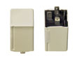 and he is having intermittent OD problems that seem to be weather related. It won't go into OD when the weather is cold. Is the relay on the relay tray? If so, which one is it?
[Diagnosis:] Yes it does sound like an OD relay. If I remember correctly on 740 it is by the Ashtray/FuseBox. It is pretty common component failure on the bricks. It will be a white Hella relay. Pretty simple to change. The relay is about $40-43 through Mail order from dealership. In my case I was sure it was the wiring, switch or solenoid, as the relay looked just fine. But as soon as I replaced the relay, all problems disappeared. The relay is about $40 from the dealer, or you can probably find it cheaper from a second source...it appears to be a standard Hella relay.
[Response 2: Michael Daley] I have just repaired the o/drive relay and rather than pay the UK£40 that the volvo dealer wanted for a new one, I took the top off the relay - all that was wrong with it was a cracked solder on the circuit board. Fixed with a soldering iron in 5 minutes, saving myself £40!!
 [David Brewster] Wave solder joints can crack and cause relay failure, as shown in the photo. These can be easily repaired with a soldering iron. For a more detailed discussion of relay repair, see Relay Repair vs. Replacement.
[Another OD Symptom:] I have a '93 940T with an AW71L transmission (or so I've been told...) Today I was driving on the highway and it momentarily dropped out of overdrive into 3rd, at the time I was at minimal throttle. I dismissed that as a hiccup. An hour later (after making a couple of stops)I began driving and I noticed that the tranny would not go into OD, 3rd gear was the max. All of the other shifts are perfect. I tried pressing the OD cancel button a few times, and I checked the related fuses - no changes. Am I looking at replacing the overdrive solenoid on the tranny? If so, can anyone give me a part# and/or approx. price? [Response: Abe Crombie] It is an AW71 no L. The turbos didn't get the locking torque converter feature. The trouble sounds like the typical OD relay failure. The relay is behind the ashtray in the fuse/relay panel. I believe it is white on that car and square in profile. The fuel system relay is the one to the left that is rectangular.
Shifter Overdrive Switch:
[Inquiry] My overdrive will not lock out and the relay is fine. [Response: Editor] The switch on the shifter is likely bad. To replace it, see the link above.
Solenoid:
If your overdrive engages late or not before the transmission warms up, first try replacing the relay and flushing the fluid. If this does not solve the problem, a new solenoid often will.
AW 70/71 Overdrive Problems: Wiring to Solenoid, Solenoid.
Electrical & Wiring Problems:
[Rob Bareiss] The overdrive solenoid should click on and off with a very noticeable click. You need to be sure you're getting 12 volts at the solenoid. If you haven't got 12 V, you need to check the wires at the OD relay socket in the fuse box and thence to the solenoid itself. My '88 has had numerous problems with the electrical connections at the OD relay on the fuseblock, so I would be checking there first.
Wiring Connector: [Eric C] The plastic wiring connector which connects to the overdrive solenoid (attached underneath the car at the rear of the transmission) can come loose. In my case, it snapped in place yet had 2mm of play and was not snug. I cleaned out the connector with contact cleaner, allowed it to dry, then used heat shrink tubing to keep the connector in the snug position after snapping in closed. It worked; no more overdrive problems.
[Another Tip] Sometimes there is corrosion in the joint between the connector and the wire..it may look fine and even will light a test lamp but will not allow enough amps across it to fire the solenoid. Take it apart, clean and deoxidize, then reassemble with silicone grease.
Wiring. [C. McGrew/Scott] Check the wiring under the car from the shifter to the solenoid. It tends to deteriorate near the shifter and at the connector leading to the solenoid itself. Jiggle this to find internal wiring breaks. If you install a new solenoid, then also install more chafe guards (3 inch pieces of hose) all along the wire. Make sure that the white wire that comes down from the shifter does not ground out on the car due to worn insulation. [James Souther] A couple of my solenoids had the white wire break from vibration right before the soldered tab under the rubber potting, a bit of solder and RTV for potting and the solenoids were returned to service costing only the two new o-rings.
Solenoid Operation/Diagnosis:
[Rob Bareiss/Scott] The solenoid is normally closed, cutting off the fluid flow necessary for 4th gear or "overdrive". When energized with the overdrive arrow light "off" the solenoid opens up and allows the trans to shift into 4th. The solenoid must pass fluid through when energized, or it's either not working or plugged up with dirt. Just because it "clicks" does not mean it is passing any fluid. The first test is to park in a quiet place, open the drivers door and switch the OD on and off while listening for a click under the car. If you don't hear it then it is bad. If you do hear a click that does not necessarily mean it is good: it could be dirty and not passing fluid.
[Steve Sakiyama] There have been a few posts on autotrans overdrive 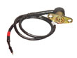 problems (won't shift into 4th) when the brick is cold. The problem disappears when the car warms up. I have an AW71. When cold it would not go into 4th (OD) until the car had been driven for 10 minutes. This would happen more and more frequently until it was a regular pattern. I checked/dealt with fluids, OD relay, wiring, and downshift cable but the ultimate problem was the overdrive solenoid which sits on the side of the tranny. Although I had bench tested it and it seemed fine,an experienced tranny tech said it just doesn't sound and feel right. Replaced it with a used one (with the two inner o-rings), and the brick is fine. [DougC] According to Bentley, with the solenoid in your hand and disconnected, you should cover the oil passages between the o-rings, and blow through the hole on the end of the solenoid. The valve should be tight, and no air should pass through. With it energized with 12 volts, you not be able to blow air through with the same holes uncovered. It says also to check for blocked passages and damaged o-rings.
Solenoid Removal/Replacement:
Tools. What kind of special wrench do I need to get 2 bolts out of solenoid to remove it? Doesn't appear to be much room for tools or hands.
[Ryan Ridgely/R Haire/SML] Wear eye protection. For ease of removal, GearWrench brand ratcheting box wrenches with the flexible head work well and do not force you to drop the transmission. Support the transmission with a jack and remove the cross member (although one user did the job whilst lying on the right side of the car and reaching underneath). Then lower the trans about an inch to give you enough room to CLEAN the area around the solenoid until it is spotless before ever attempting to remove it. Do NOT lower it so much you crush the distributor cap against the firewall. To remove the solenoid, you need a stubby angled 12 mm wrench. The rear bolt is the more difficult of the two. It is snug up in there and you do not have much range of motion. A "gear wrench" is ideal to turn the bolt. Be prepared for a lot of oil to run out: about a quart/liter. [Tip] I have used a short (approx. 6") angled/bent 12mm open end wrench that I heated and bent myself. Access is difficult: you may have to remove the linkage and drop the transmission support (placing a jack and large wood plate beneath the pan to support the tranny). [Tip] Bend a flex socket handle to fit and use a 12mm socket on the end to remove the solenoid bolts. [Tip] Use a smaller 1/4 inch drive socket set to remove it. Note that there are two o-rings to pull out.
Dirt. [Rob Bareiss] Replacing the solenoid requires that NO dirt get in that transmission. Lots of brake cleaner, Gunk, power washing, and probably use of a toothbrush and more brake cleaner will get the area acceptable. You might follow up with compressed air delivered by a J-tube to remove dirt and little rocks lodged up behind the solenoid. Haynes suggests the use of a sheet of cardboard over the trans, up against the tunnel to keep grit from falling in from above. Dirt and transmissions disagree.
Don't get any dirt into the solenoid when you replace it. This is a filthy area and it's easy to do this. The plumbing internal to the solenoid unit, which has a right angle turn at the valve seat, can plug up. You may have to pull the OD solenoid, rig it up to the battery to turn it on and blow it out with WD40, carb cleaner, compressed air, or any similar pressure source, preferably with a little straw to get down into the holes.
[Editor] Two users reported that removing the solenoid and turning the engine over seemed to pump enough oil through the recess to clean it out and enable operation. This is messy, though. [SML] Before re-installing the solenoid, clear the oil passages in the transmission by slipping a tray under the tranny, starting the car and quickly shifting the auto trans gear lever from P through R,N,D,2,1,P then quickly off. About a 5 second process. A flood of trans oil will squirt out from the car hopefully clearing any blockages.
[C. McGrew] My transmission was leaking fluid and was oil soaked from an engine rear main seal leak. The solenoid rubber cap becomes brittle and then it's good bye. Be sure to buy the two o-rings for the solenoid. Coat o-rings with plumbers or silcone grease for sealing and ease of install. It's not that bad getting your fingers in the correct position to replace the two bolts. Re-torque to 7-12 ft-lbs to tighten the solenoid bolts.
Rusted Bolts. [James Souther] If the solenoid mounting bolts are rusted, the lockwasher is only rusted to the solenoid flange and the bolt head, not in the threads as the case is aluminum so PB Blaster or Kroil will help but not solve (no pun intended). If you use penetrants, use starting fluid or brake cleaner to clean off around the solenoid base before you start as both dirt and penetrants are not good for the inside of the transmission. Second, free the solenoid wire cable and the brackets before trying to loosen the bolts. This lets you get better access if you flop that out of the way. If needed you can take the nut off the shift shaft input and move it away, however, you need to hold the lever so you do not stress against the transmission valve assembly inside. The lever goes on with a rectangular notch. Third, attack the bolts which set very close to the solenoid body and come out by hand after a turn or two. IMHE the original bolts seem way overtight due to being threadlocked so what works is a quarter inch 6 pt socket with extensions to get down on top of the bolts or a thin box end wrench and lots of force. The posture is pulling the car and the wrench or ratchet together so you can put enough force on it. In a dozen or so times, the bolts mostly "crack" loose. When you get it out, check to make sure the old o-rings are not stuck on the transmission flat. Finally, take heart, installation is a breeze compared to taking it out.
Eliminating the Overdrive Disabling Function at the Relay. [Bill Foster] If you never ever use the overdrive switch to disable the OD, you may want it permanently enabled. To bypass it, use a short jumper with 2 1/4 inch male terminals inserted in the switched hot terminal to the solenoid terminal of the overdrive relay. The wiring diagram is often on the relay.
Eliminating the Solenoid and the Manual Downshift System: 
You can also pull the solenoid entirely, replacing it with a metal plate, and remove the ability to use the button to manually shift down into third. See the link below for IPD's solution to solenoid troubles.
[E. J. Ohler] Forget about a new $150 solenoid and $50 relay: take the solenoid out, cut the wire off and cap the end, grind a small groove between the center hole and aft hole in the solenoid face, and reinstall to allow fluid to move and disable the solenoid as a solution to solenoid troubles. Use a Dremel 1/8 inch grinding tool (the metal is hard so you will use two) or a diamond bit. Clean the matching holes in the tranny using drill bits the same diameter, but don't drop them into the transmission. Replace the outer O-ring but not the inner where the groove passes through. From start to finish this is a 3 hour job that saves you a lot of headaches. You don't need the manual 4-3 downshift in most instances anyway.
Solenoid Quality Reports:
[Tip from Dan Marino] My recently-installed Scantech OD solenoid failed. I discovered that the rubber top cap (the part where the electrical wire attaches to the solenoid) had totally split away from the metal solenoid valve parts. Basically, the top blew off of the thing. The result, massive transmission fluid leakage. My conclusion is that this ScanTech overdrive solenoid suffers from poor quality construction, cheap-o materials, and design flaws. The next day I was able to pull an original Volvo overdrive solenoid from a junker for a cost of $5.25. A quick comparison showed the Volvo part to be of superior design, more metal, and less plastic/rubber.
 Solenoid and Overdrive Removal. [Ken Crossner] For you folks who wish their automatics were simply completely automatic without any tendancy to fail and lose 4th (especially during this gas crisis time), IPD came up with a solution! They're selling a Solenoid Bypass Plate (product code MD7071K - $39.95.) Remove the solenoid, cover the hole with this plate, and you're left with a 4-speed automatic transmission -- the 4th (OD) gear works normally, and you can dispense completely with all the other components (relay, shifter switch, wiring, etc.). Nothing left to fail, ever! You merely lose the ability to manually downshift into third gear, which you probably never used much anyway. You can remove the overdrive relay to turn off the lamp permanently and remove the power to the +12V lead to the solenoid.
[John Orrell] there is a almost free way of doing this. Remove the stock solenoid, remove the inner O-ring and machine/grind a groove in the face of the solenoid between the two small holes. Replace the outer O-ring (not exactly free, but cheaper than 39.95) and reinstall the solenoid.
Governor Pressure Test. [Tip from Abe Crombie] The governor is best checked with a gauge attached to the tap point on driver's side of trans on case just forward of tailhousing joint. This plug is a 8mm X 1.0 bolt. The gauge fitting used is an o ring sealed hollow bolt with a cross-drilled bolt that goes through fitting in hose from the Volvo special tool gauge. You may be able to fashion something like this. The gauge needs to be able to read 60 -70 psi at least. The pressure should correspond more or less to the road speed once you get to 10 mph or above. Approx 1 psi per each mph.
ZF22 Damage in Park. [Inquiry] I have a 1986 740 GLE. I took the vehicle for emissions testing in March. Part of the test is to rev the car for several minutes while they check the high idle (2500 rpm). My transmission started slipping badly when I left, and lost all forward gears the next day. I replaced it with a junkyard tranny (I know its a risk, couldn't afford a rebuild) and the car has run great for about 3,000 miles. My tags have expired, so I went back for another emissions test (it failed the first time). Unfortunately, it failed again, but this time, it would hardly move. I made it about 1 mile, then had to be towed. I was told by a transmission shop that the ZF 4HP22 transmission cannot be revved in park without causing damage and that a bulletin went out to all emissions testing facilities. A dejanews search found several old posts saying smog tests would kill this transmission, something about after being in forward gears then put in park, some pressure is still on the clutches and will wear out clutch pack A. This seems to apply to Volvos, BMWs and Jags with the ZF 4HP22 transmissions. The emissions testing people have called me 5 times since yesterday, they seem concerned and are having my car towed to have the transmission checked. They will not admit to any bulletin, but obviously seem concerned about liability. My question: does anyone have any info on these transmissions? I have heard of a Volvo bulletin on this, and an EPA bulletin (may be just California EPA, not sure). Bulletin numbers or a copy of the bulletins would be great. I'd like some facts to present them with since they are listening, but so far just have a little info from old newsgroup posts, and from a conversation with a transmission shop.
[Response 1: Mark Aarabi] What you have heard and read is absolutely true. Yes, there is a TSB out.(Volvo TSB 2525, 9/91, for all ZF-equipped 1985-88 740 non-turbos).. and Yes, there was a memo from EPD to all emission testing facilities about this concern (at least here in Georgia). What state are you in and do you have any idea what type of equipment they use for testing? The software on most BAR97 equipment will automatically bypass the 2500 RPM section of the test on these particular vehicles.
[Response 2: Bruce] Most all emissions center should be aware of this problem. Other cars have the same problem that use the ZF tranny. As the one post stated the test machines will by-pass the rpm test with a ZF tranny. The emission shop should replace your tranny. But getting them to admit fault and do it could be a problem. For others reading this, 1985, 86 and 87 only 740's used the ZF tranny. (Editor's Note: ZF-22 cars have P-R-N-D-3-2-1 on the shift quadrant and NO overdrive button on the shifter.) Turbo models use the AW-71. For the above model years, if the gear shift lever does NOT have an OD button you have a ZF tranny. With an OD button you have the AW-71 tranny. One way to test the emission on a ZF tranny is to raise the back wheels off the ground, put the car in drive and rev it up to 2500 rpm for testing. In gear it will not do harm. In neutral or park and revving, the tranny pump does not pump oil. I was told this by a transmission repair center.
Volvo Technical Service Bulletin on This Problem:
[Editor's Note:Summary of Volvo TSB 2525, 9/91:] Before beginning the High Idle Emission Test Sequence make sure the car is at operating temperature. Place transmission into park and switch the ignition off for 30 seconds. Restart, but DO NOT move the selector through the forward or reverse gears before or during the test and DO NOT EXCEED 2000 RPM. The first stage of the test is at 1850 rpm for 30 seconds, the second stage is at normal idle for 30 seconds. If you fail the test and have to do it again, then DO NOT proceed with the programmed catalyst preconditioning test sequence. Abort the test, place the transmission into park, precondition the catalyst at 1850 rpm for 4 minutes, then allow the engine to revert to normal idle and check the tailpipe emissions. Under no circumstances must you exceed 2000 rpm during any part of the test.
Reasons for Transmission Failure:
[Jim Bowers] Here is what I have learned from various inputs, some on Brickboard, some from BMW related sources. The transmission apparently leaves some residual pressure on the clutches when put in P and/or N. If the engine is revved in this state the clutches get burned.
[Martin] I rebuilt a used ZF and learned some about the slipping #1 clutch pack, too. The input shaft was originally sealed with metal rings which were prone to leak and leave some pressure on the clutch pack during all conditions, causing it to fail early. The rebuild kit (non oem) however contained redesigned teflon rings packed with some information on the issue. During rebuild I also discovered there are some other poor design issues in this tranny. Light alloy clutch cases which will wear rapidly, some strange sealing designs between valve body/housing and in my case also a pair of blown bearings. I used parts out of two trannies since the actual ZF problem seems to be the horribly expensive hardware, making a complete swap desirable if the worn out unit needs anything more than clutches/sealings. AW trannies does seem to be better designs, without expensive failure spots like these of the ZF.
ZF Preventive Maintenance:
[Fitz Fitzgerald] There are many people putting a lot of miles on ZF transmissions, but the transmissions are more prone to failure than the AW trannys. A few words of advice for preventive maintenance on ZFs:
- Do not rev the engine in Park or Neutral: this will tear one of the forward clutch packs to pieces.
- Change the fluid at the specified intervals and be sure to remove and clean the pan before the first fluid change. Performing a fluid flush without first removing the pan can break up some sediment in the bottom which will be sucked up into the takeup and act like sand in the bearings and valve bodies. Feel free to toss in a larger magnet before putting the pan back on.
- Run synthetic trans fluid if you can afford it. Mobil 1 full-synthetic is worth the improved longevity.
If the transmission fails, swap it for an AW.
ZF22 Fails; Swap for AW? [Inquiry:] The ZF4HP22 tranny in my '86 740 just started spewing fluid from inside the bellhousing (1 pint/mile). Given the reputation this tranny has, I'm undecided as to whether I should rebuild it or replace it with an AW71. Has anyone done this swap?
[Response:] Do the swap. Any AW70 or 71 will work from 82-on. The basic gearbox is the same, but some are better or stronger than others. If you're going to buy one from a junkyard, get one from the latest years possible. (89-93 non turbo, since they have a lock-up converter.) If you use an earlier gearbox, you will need to plug the speedo drive hole in the output shaft housing. I don't remember if the flex plate is the same or not, you may need that. The driveshaft is different. If you order it from the boneyard, tell them you're doing the conversion. Remember that the car didn't know what transmission it was going to get, so the interchange is ''bolt in.'' I think if you get the necessary parts (with relatively low mileage) for under $1000.00 you did all right.
[Response: Dick Riess] Actually quite easy to do:see the Auto Transmission Conversion: ZF to AW FAQ file describing how to do this. . Best bet is contact someone like Strandbergs in WI 800 448 5121 and they literally send you a good used unit plus all parts. I did an 86 740 couple of years ago and works great. Here are the parts you will need: transmission, cross member, transmission mount, drive shaft front half, gear selector unit, relay for overdrive on AW unit, some wiring. Get good wiring diagrams to help you out.
[Response: Kane] All 4-cylinder trannies bolt up fine, including pre-'86 240 series ones. One difference is the speedo ... the pre- had a speedo gear at the rear tailcone, where as the 740's and later 240's had an electronic pickup sensor at the differential. That tailcone can be swapped with one that doesn't have the output gear.
Transmission Removal:
Transmission Removal. [John Orrell] Don't consider trying to remove your transmission with either a dedicated transmission jack or a $40 transmission adapter for your floor jack from Harbor Freight or the like. Here are the steps to remove your transmission:
- Set parking brake and disconnect battery negative/earth
- Release kickdown cable at throttle pulley and remove dipstick
- Use floor jack under the front suspension cross member... in the center.
- Jack it up to maximum lift range of the jack and put quality jack stands under the front factory jacking points. Don't use cheap or undersized stands.
- Let it down on the jack stands.
- Put floor jack under the center of the rear differential.
- Jack up the rear end as far as the jack allows, make SURE that the car does not rock the front jack stands forwards or backwards!
- Put another set of jack stands under the rear factory jack points and let the jack down.
- Drain oil from transmission
- Disconnect oil cooler lines from radiator - use a counter hold wrench at the radiator to prevent damage. Also disconnect lines at transmission. You will bathe in oil. Remove line holder at bellhousing (l -10mm bolt). Remove lines from engine bellhousing.
- Loosen nut holding filler tube - dipstick holder from oil pan. Once pan is drained, put plug backs in and block holes vacated by lines and filler tube.
- Disconnect shift levers from transmission. Two E clips.
- Disconnect driveline at back of transmission and front of differential.
- Support transmission with a transmission jack, safely secured to the tranny.
- Remove center support bracket. Total of 6 bolts. You will need the plate for mounting the new drive shafts.
- Remove exhaust pipe support near the back of the transmission. Not on all cars.
- Remove nuts from exhaust pipe to manifold (3).
- Remove bolts holding exhaust pipe to bellhousing.
- Free exhaust pipe from exhaust manifold.
- Remove aluminum engine support bracket under the engine. This binds engine to bellhousing.
- Remove 4 bolts holding torque converter to flexplate. You will need to counterhold the flexplate.
- Loosen and remove starter bolts.
- Remove distributor cap and rotor. You don't want to crush it against the firewall. Alternatively, support the engine using a hook at the rear connected to an engine lift.
- Remove transmission crossmember. Two bolts on each side and one nut holding transmission to the crossmember. Remove the bolt from the transmission - need to tap with a hammer once the crossmember is removed.
- Remove all bellhousing bolts. The top bolts can be reached from above using a 19mm wrench.
- Carefully pull transmission back until clear of bellhousing and lower. You will probably take another transmission oil bath, especially if the torque converter decides to come out. Best to cross wire in the torque converter to prevent it from slipping out: wire from ear to ear of bellhousing portion on transmission. Remove transmission from under the car.
- Remove flex plate - loosen bolts in a cross pattern. For a counterhold to secure the flywheel, install a very strong C clamp through the starter hole in the block, squeezing on the front and back of the flywheel.
- Mark or know the position of the flexplate on the crankshaft, as it prevents timing problems later.
Installation. This is generally the reverse, but position the torque converter and orient the flex plate correctly on reinstallation. Remove and install new rear main engine seal:see instructions for this as well as other items skipped in these instructions. Torques on reinstallation include:
- Fluid dipstick tube to pan nut: 90 Nm (66 ft-lb)
- Torque converter to carrier plate bolts: 50 Nm (36 ft-lb), torqued alternately in a cross pattern
- Torque converter housing bolts to engine: M10 are 42.5 Nm (32 ft-lb); M12 are 72.5 Nm (52 ft-lb)
- Center support: 26 Nm (20 ft-lb) tightened alternately in steps of 7 Nm (5 ft-lb)
- Oil pan bolts to transmission body: 5 Nm (3.5 ft-lb)
- Coupling flange on output shaft: 45 Nm (34 ft-lb) using Loctite
- Oil cooler connections on side of transmission: 25 Nm (18 ft-lb)
Bellhousing Bolt Removal. See the discussion in the Engine: Mechanical section.
Torque Converter Alignment on Transmission Reinstallation. [Inquiry] Why is the shaft on the torque converter that goes into the transmission slotted on both sides of the end of the shaft?
[Response: Chris Herbst] Those slots have to be aligned with the oil pump on the inside (they fit over the extrusions or dogs inside the trans). If you don't line them up you'll chew up the torque converter and the drive gear inside the transmission, which basically means getting another transmission. In addition, your oil pump will not engage. In other words, alignment on reinstallation is very important. See also the notes on alignment related to engine rear seal installation.
[Jerry Andersch] When the torque converter is properly seated it should sit 1/2" below the bell housing flange. If it's flush with it, it's not seated all the way. With the tranny slightly angled up (bell housing higher than the tail)work the TC back and forth until it seats, sliding down 1/2" of so below the bell housing flange. When installing the tranny make sure the BH is slightly higher as you move the box into place, so the TC does not slide forward and out of place. Bolting the autobox into place with the TC not properly seated can damage the transmission.
Rebuild or Replace Information:
The transmission in my Volvo is fading and needs to be rebuilt. What should I do? [Rob Bareiss] Not worth rebuilding. Good used ones are SO CHEAP that there's no reason to pay $900 for a rebuild, vs. $250 for a junkyard trans. The downtime is a lot less too- pull yours and chuck it, bolt in the new used one, 4 hours you're done. Compared to 3 days on the bench waiting for the rebuild. [Rhys] The Aisin Warner 70 is an excellent trans, very long lived. A good used one is always an easier way to go. The rebuild kit for soft parts is only about $150.00, but if you need any hard parts, the cost goes up dramatically. And rebuilding one is a challenge the first time. You'll need the factory manual, which covers the BW55-AW70 trans. Very good publication, but pricey.
Transmission Interchange? [Jay Simkin] In the 940s and most post-1989 740s, the trannies used were made by Aisin-Warner. These units are very robust. Non-turbo cars usually had an AW70L or AW71L (L = locking torque converter) while turbo-equipped cars came with the AW71 unit (non-locking torque converter). Look for a used AW70, AW71 or 71L (depending of whether the car has a turbo or non-turbo engine). These AW units can come from a 740 or a 940. The 24-valve (6 cylinder) 960 series cars were equipped with the AW30-43 unit. The AW30-43 is computer-controlled, and does not interchange with an AW70 or AW71 unit.
Replacement Tips. [Jerry Andersch/Others] See the FAQ section on rear engine seal replacement for more information on removing and replacing the transmission.
Used Transmissions. [Marlin Mangels] When you buy a used transmission to replace your failed unit, get one with pink (not brown) fluid to make sure you are not acquiring a soon-to-fail unit. Buy one that comes with its torque converter. Torque converters vary in application and matching the TC with the tranny may be difficult if you don't have the original. Used transmissions may be sourced from junkyards anywhere. Pay attention to model and lockup function on the identification tag.
Pulling the Tranny. Best technique is to use a rented transmission jack. In my experience, after trying to get the fill tube off without success I gave up and removed the tranny with the pan and tube in place. It is possible to drop and reinstall a new tranny with it still attached; just make sure you have someone guide it up while you're doing it because it will get caught. On reinstallation, once you get the tranny lined up make sure to use the rear of the tranny to push it into place; this is the only way to do this. Attempting to force it in by putting the mounting bolts in doesnt work out very well. If you have a problem getting it to line up with the engine i suggest you get a floor jack from a friend and jack the front of the engine up just a little (but not by much or you might cause damage in areas not intended.) Don't tilt the tranny too far forward or your torque converter will fall out. If you have to pull the pan off, be ready for a mess. Fluid will continue to drip for a long time. You need a large pan to catch the dripping oil. If you plan on re-using the kick-down cable, be sure to secure it as you remove the transmission. I broke mine at the plastic fitting where the cable enters the transmission.
Torque Converter. The TC will pull straight out ... or fall out if you tilt the tranny too far foward. I removed my replacement pick and pull convertor to replace the main front seal. I let the TC drain into a clean coffee can to get all the old ATF out of it. After replacing the seal and pouring some AFT into the converter it's very important to seat the TC properly on the oil pump drive ... The converter should slip onto the drive and seat below the edge of the bellhousing, not flush with it. Turn it back and forth until it slips in to place. If it's not seated properly or slips forward out of seat as you install the transmission in your Brick, the oil pump drive will not be properly engaged and things will get chewed up when you start the motor. A properly seated conveter will sit about 3/4" below (or back from) the front edge of the bell housing.
Engine Rear Seal. Now is a perfect time to renew the engine rear seal, which requires removal of the transmission.
Parts Renewal. I removed the TC and then using a seal puller removed the front main seal. Slathered a generous amount of ATF of the new seal and carefully seated it so it was not cocked. Make sure you lube all new seals. I also replaced the cross (selector) shaft seals,solenoid and cooler line o-rings, kickdown cable o-ring and kick down cable, pulled the pan and cleaned it and the pan magnet, pulled the mesh filter screen and cleaned it, and replaced the pan gasket. Replaced the rear bushing, oil seal, and gasket. I also put in new nylon shift linkage bushings and overdrive solenoid o-rings. All this is a lot easier to do when the tranny's out of the Brick ... and if done correctly will assure you not a drop of ATF will leak out of your new autobox. On reinstallation, I replaced the kickdown cable. I filled the new box with approx 8 Qts of Mobile 1 synthetic ATF and a dose of Lube Guard.
Transmission Rebuilding Instructions: Valve Body and Complete Transmission. See Brad Wightman's illustrated FAQ description of the valve body service in AW-7X series transmissions. Don't so this without the Volvo illustrated OEM manual. For complete rebuilding instructions, see Kenny's detailed and lengthy illustrated instructions in the FAQ file which has illustrations of valve body components from the OEM manual.
AW Transmission Parts and Rebuild Technical Help . [Tip from Frank] The AW (Aisin Warner .... Asia's version of Borg Warner) is the most common import tranny out there from Toyota to Isuzu. There are several good service books, better than Volvo's own technical publication. My suggestion is to call either of the two suppliers below and ask for the best novice book they have (Trans Mart will even give you the info to get it yourself if you wish, but Trans Star won't). Read the book cover to cover before touching the tranny. I'd even go so far as to suggest you get the service updates manuals from the same location. If you decide to rebuild your unit, here are the best places in the United States for a transmission kit and parts:
- Trans Mart (division of ATC Distributing) phone# 800-633-3340 (they'll give you a number that is closer to you). GREAT customer service
- The next best is Trans Star 800-321-8830 (they're a little higher on parts & their customer service is good.)