Electrical Instruments
"Service Engine" Light Reset in Various Models
Cluster Removal:
740 Instrument Cluster Removal
760 Instrument Cluster Removal
940 Instrument Cluster Removal
960 Instrument Cluster Removal
Cluster Cleaning/Disassembly and Connector Wire Removal
Lamps and Switches:
Replacing Instrument Cluster Lamps
Replacing Heater Control Unit Lamp
Center Console Lamp Replacement
Shift Indicator Bulb Replacement
Troubleshooting:
Warning Lights Flickering: Bad Alternator Brushes
Fuel Gauge Fluctuates or Fails to Work
Cluster and Instrument Interchangeability
Bulb Failure Sensor Lamp Won't Go Out
Speedometer Relay and ABS Lamp
Windshield Wipers Operate When Horn Is Pressed
Cruise Control Won't Work or Incorrectly Disengages/Re-engages
Key-in-ignition/Seatbelt Chime Won't Turn Off
Accessories:
Adding a Warning Lamp for Loss of Engine Coolant
Adding Accessories and Wiring Them Through the Firewall
"Service Engine" Light Reset in Various Models.
740 Pre-89 and 760 1987. [Procedure:] There is a reset button on the back side of the instrument cluster. It is located on the back side about where the 80 mph reading is. You may be able to get your hand up from the bottom to press the reset by first removing the lower kneepad. You can also remove the two outer lower screws on the instrument cluster and gently pull out the instrument panel enough to get your hand behind to press the reset button. Remove each small plastic cover to expose the mounting screws. The speed nuts into which these two are screwed sometimes fall off, down into the dash area. There is just enough slack in the harness to allow pulling the assembly over the steering column to get at the reset button. Press the button nearly flush with the back of the cluster for proper reset. A lot of people just remove the service bulb on this model to avoid the trouble of having to reset light every 5000 miles. N.B.: 740's with SRS do not have service reminder lamps in these vintages.
740/940 1989-1995, 760 1988-1990, 960/90 through 2000 .
On these cars there is a small black, circular rubber plug in the clear plastic of the instrument cluster. Carefully remove the plug ... then take a very small phillips screw driver or even a nail and push in the re-set pin just behind the hole in the clear plastic. The button will click. Replace the plug and the service light is re-set. The later 960/90 series cars have 10k service intervals. Don't let your dealer tell you that you need a "scan tool" to reset this lamp: they are referring to the "check engine" lamp, not the "service engine" lamp.
Caution: Before you remove the cluster, disconnect the battery negative so that any contact between the rear of the cluster and the metal surround will not result in a short and a fried circuit board.
Cluster Reinstallation: Before you reinstall the panel, make sure the small soldered connections on the bottom are intact and you have a piece of tape protecting them. They can be torn off when removing or reinstalling.
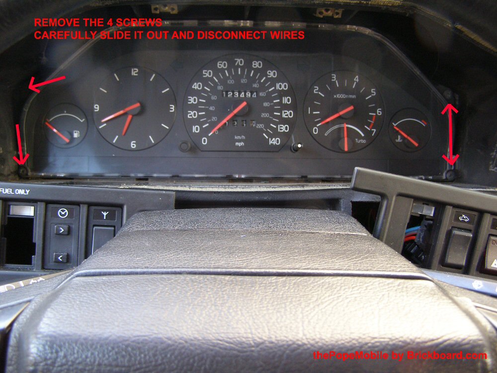
740 Instrument Cluster Removal. It's very simple. Place the turn signal and wiper stalks in the down position. Take a super slim screwdriver and remove the small plastic cap surrounding the small clock set knob on the left and the cap surrounding the dash light dimmer on the right. Under each of these is a phillips screw. Remove and pull the whole cluster out. Don't even need to remove the steering wheel. If it 's the first time out, the wiring will be held in tight behind the dash by plastic ties. You can cut these ties which will afford you enough room to twist the cluster around and replace any bulbs etc, or mark each electrical plug and unplug enough of them to give you the room you need. [Jim] Later 740 cars (e.g., 1991) may have cluster bezels similar to the 940 below with a flat spring on each side, pressed down with a screwdriver through a slot.
760 Instrument Cluster Removal.
[Inquiry:] I can not figure out how to get the instrument cluster out of my 89 760. It looks like all of the trim around the dash switches has to come off, then take a couple of screws out on top of the dash insert. I can't seem to make anything move.
[Response: Chris Ascoli] I found out the hard way. Besides the two screws in the upper black insert, there are I believe 3-4 more screws hiding behind the air vents, one per vent. Take each air vent and push the top all the way into the dash as if you want to shoot the air up at the ceiling of the car. Once you do this, you should be able to see the screw in the upper portion of the plastic JUST behind the top of the vent. It's kind of tricky to get at, but you should be able to squeeze a Phillips head in there and remove them. Forget to do this and you'll hear a Crrrrrraaaack of the plastic housing surrounding the temp controls, etc. As you can imagine, that's how I found the screws. Thank God I didn't break it enough so that it hung away from the dash when reinstalled. Once you get the vent screws, just pry with a little force and it should come out. But if it seems to hold up somewhere, check for any other screws at the binding point. The vent ones are definitely key though.
 [Davide D'Angelantonio] To remove the cluster in my 940SE (Euro configuration similar to 760), first remove the trim. including the two plates on the right and on the left of the steering wheel that hold all the switches. There are no screws here, but pry them carefully since these are made of plastic that has certainly lost its elasticity and is brittle. I found it helpful removing the cover plates for the spare switches so that I can pull the plate by inserting my finger inside the empty hole. You can leave the plates with the switches, hanging by the wires, since you will neet to make rook for the upper dash to come off.
There are 9 screws to remove:
- Inside the upper part of the left climate vent
- Inside the two central vents (2)
- Above the speedometer (2) covered with a plastic lid
- The following are visible after having removed the switch plate
- Above the light switch
- Above the A/C control panel
Now you can pull the big, black plastic dash cover off. It is one piece with the vents. Once that is gone, you can remove the instrument cluster by unscrew ing the 4 screws on the 4 corners of the cluster. Slowly pull the cluster forward. With the help of a screwdriver, push the black wire, running on top of the cluster, away from the two wire holders. Slide the left side of the cluster out first. Disconnect all the electrical connector, by unlocking the plastic retainer tabs. CAREFULLY unplug the turbo pressure hose. It has a white 90 degree angle pipe fitting. LEAVE THE WHITE FITTING ON THE HOSE. Instead disconnect the white fitting from the cluster.
940 Instrument Cluster Removal
[Inquiry:] How do I remove the instrument cluster in my 940?
[Responses: Abe Crombie and IanB] Disconnect battery negative and place the turn signal and wiper stalks in the down position. Insert a narrow screwdriver through the slot in the side of the metal bezel (see photo arrow). You will feel a spring clip as you push into slot. Hold the screwdriver at the angle shown in the photo. Push the clip hard while pulling toward you with the shank of driver; the clips are attached to the dash and are also robust, not easy to damage. Use a hooked dental pick to pull the cluster bezel while depressing the spring clip if it is stuck. The cluster mounting surround is alloy and is held by the cluster screws. There are lugs cast into the sides of the surround onto which the clips lock. Do one side only, it should come out easily once you get one to let go. One clip each side, nothing else holds it in. After you get it out remove the cluster by taking out (4) Torx screws (DON'T DROP THEM) and it's free. Remove by pulling forward until you can see the rear electrical connectors. If it's turbo you have a gauge hose to disconnect at a joint about 8 or 10 inches from gauge. The latter is easier to do with the kickpanel above brake removed. Before you replace the bezel, grease the spring clips and the lugs to make future removal easier. To replace the bezel simply push it in and the clips lock onto the lugs
Difficulties? This bezel can be tough to remove. Some tips:
[Chuck Lee] I took off the knee pad and worked the left clip from underneath the dash. Get the left clip free, pull the bezel out a little and the right clip releases easily. More stuff to take off but a lot less cussing
[Paul Larson] When I looked through the vent opening, I saw the steel clip moving, being pushed by the screwdriver....problem is, the screw holding the clip assembly to the alloy surround was just a tad too long to allow the clip to completely clear the retaining ears on the bezel....it limited its travel. I removed the vent and ground off the screw tip (no easy task through the vent hole) and then looped bailing wire around the clip and pulled.....finally, the bezel came free. The clips were twisted on the alloy surround, causing them to be canted way far into the centerline, making it even more cantankerous to release. That bezel would have never come out without going through the vent opening and grinding that screw.
960 Instrument Cluster Removal.
[Inquiry] I'd like to pull my 960 instrument panel. See the 940 information above for basic removal. The 960's fancier dash has what looks like a one piece plastic trim panel that covers everything above the wood strip (with the switches). I suspect that there are retainers somewhere, but I don't want to risk breaking the plastic by prying where I shouldn't. Possibly the wood trim comes off first to expose fasteners for the upper panel? Anyone have the right steps to get the instrument cluster out?
[Tips] Here's how it went in my 1996 960:
- Remove the radio. You may have to turn the ignition on the move the gear shifter out of the way to get the radio out. Just slide the radio out but do not unplug any connectors on the rear until you have disonnnected the negative battery terminal in a few steps. Be sure you have the radio code to get it going again. Take out the ashtray. It has a spring under the lip.
- Disconnect the negative battery terminal. Now you can disconnect the radio plugs and set it aside.
- Remove the air vent grates. To do this pull straight out. Sometimes it helps to tilt them to get a grip. Remove the screws under the top of the vents.
- There are two torx screws by the ashtray that hold the large wood grain trim piece in. Undo these. To remove the large piece, use a screw driver to pry the two clips inward. There is one on each side of the cavity where the radio goes about half way up.You will have to unplug a few wires as you go such ashtray lights etc. Make note of where the light plugs go.
- Remove the plugs from the switches in the wood grain panel. Mine were sun roof and hazard lights. Make note of which plug goes where by color.
- Gently pop off the wood grain trim under the cluster. It has tabs that hold it in place. Be very careful. Of note here, my 960 does not have spring clips holding the wood trim on, contrary to the FAQ section on wood trim removal.
- Follow the perimeter of the black plastic that is around the cluster. There will be several torx screws.
- Pop the covers off the screws on the underside of the 'shelf' above and around the cluster instruments. I think there are two or three. Undo the screws. I think they are a torx 25. The long black piece that goes along the front and around the cluster should slide right out.
- There are four torx screws that hold the cluster itself in. They are around the four corners of the cluster. Undo these and the cluster should slide toward you with some coaxing.
[Response: Tom Irwin] That is a very tricky job. Especially if you have that wood crap all over it. It is almost impossible not to break one of those strips. As much as I hate to say it in a DIY forum, you might want to have a specialist or *ugh* dealer look at this. Check for super glue repairs when you get it back too. [Editor] Volvo OEM manual is invaluable here, showing locations of screws, etc. They also warn you that the wood laminate strips are "extremely delicate", so beware. See the FAQ Section on wood trim removal for details.
Cluster Cleaning/Disassembly and Connector Wires. [Inquiry] There is dirt behind the clear cluster front and marks on the inside of the plastic. How do I clean this? [Bryan Warfield] Remove the cluster and look at the back of it. There are about 12 long philips head screws that hold the sections together. Remove them and you can clean the inside of the clear plastic, faces of the gauges etc. Make sure you have a good quality brand name #2 philips, in good condition (no wear on the tip) as the screw heads are soft and prone to rounding out. The printed circuit foil is fragile, so be extra careful not to damage anything. Most of the screws that hold the cluster together do not go through the foil, they are around the edges and the ones in the middle are in large holes in the foil in direct contact with the white plastic. There are other screws that go through the foil and make the connections to the actual gauges. You do not want to remove these---it is not necessary to do so to take the face off of the cluster. Remove all the big ones around the perimeter, a couple in the middle, and the two that hold the lighting rheostat to the cluster. [Editor] The screws are small, soft and need the correct size phillips head driver. Make sure when replacing them you engage the plastic: back off and then turn when you feel the threads engage.
940 Cluster Disassembly. [Randy Starkie] To separate the halves of a 940 cluster, remove the screws shown circled in the diagram. Be careful when doing this: once separated, the instrument faces are exposed and you can break off the zero stop posts very easily. Try placing the front of the exposed panel on a piece of styrofoam to provide flexible support.
Cluster Electrical Connector Wire Removal. [Jay Simkin]
To remove an individual wire (with terminal attached) from an instrument cluster connector on a 1995 and later 940 or 960:
- Turn the connector, so that the release tab is facing downwards
- Using a small (1/8”-wide tip) screwdriver, open the “door” at the back of the connector (where the wires enter the connector), by prying gently on tabs, at either end of the connector
- Look at the connectors: each one has a rectangular opening, just behind the flat tip. At the bottom of this opening, is a plastic retainer, which must be pushed down, to release the wire terminal
- To release a terminal from the housing, insert a jeweler’s flat-blade screw-driver into the rectangular opening and gently press down on the plastic retainer; then, pull gently on the wire, that you want to remove from the connector housing
- The wire will come loose. To re-insert the wire, simply push it back into place. You’ll hear a “click”, as the connector slides over the retainer
- When you’re done, close the “door” ensuring that both locking tabs engage the housing
Cluster Interchangeability Among Models and Years. See below.
Lamps and Switches:
Replacing Instrument Cluster Lamps.
[Inquiry:] How I can replace bulbs behind the clocks (speedometer etc.)
[Response: Peter James ] Remove the instrument panel assembly per the notes above. It will be limited by the wiring harness plugs and the hose for the boost gauge. I usually disconnect the hose which gives you enough space to get your fingers in to turn the lamp holders and remove/replace the bulbs. You can disconnect the wiring plugs but I don't bother, I put a mirror up on the top of the dash against the windscreen with bluetack and work from the drivers seat.
Changing Warning Lamp Bulbs. [Editor] These 1.2W 12V "grain of wheat" bulbs come in two kinds: presoldered into the integrated black socket, or replaceable separately from the socket, which can be removed from the panel by unscrewing half a turn. The former are expensive (US$12 at the dealer).
[Greg Mustang] I easily found the bulbs themselves without the holder for under 1$ each. If you have good soldering skills and good tools, you can do as I did:
- Mount the assembly on a vise. Using minipliers pull off the assembly's prongs (they are pressed in). Rip out the old bulb and discard.
- On the new bulb, straighten out the two leads. Take a strand of wire from a stranded copper wire and lengthen (solder) the bulb's leads about a cm or two each.
- Insert the bulb in the old socket, sticking the wires out the end.
- Press in the old socket's prongs.
- Solder the lengthened leads to the sides of the prongs where the old ones were. You need good soldering skills and a smaller iron or you will melt away the black holder.
I did five bulbs in a matter of 10 minutes max. ...and saved myself 60 "dealer" bucks. Good for another ten years.
Changing Panel Illumination Colors:
The dash illumination bulbs themselves are #94, a common bulb used in most dashes, and you can get several colors. I have changed mine all to red. Some of the switches use a very small bulb that I could not find colored; for these I purchased some heat resistent colored film used for theater lighting from which I made small straw shaped covers for each bulb. I do a lot of night highway driving and I find the red lighting in the dash much easier on the eyes while still making the guages very visible, rather than just dimming the standard green/blue color.
960/90 Cluster, Panel, and Interior Lamps.Here are some part numbers for the interior bulbs for 960 cars, courtesy of Jon at Borton Volvo. 800-328-7114.
- 30710781 glovebox bulb with socket US$6.80 ea
- 9130288 rear ashtray/center console bulb with socket (blue tint on bulb). One bulb lights up both areas. $5.74 ea.
- 9130294 gearselector bulb w/socket and wires. The bulb can be replaced separately from the socket. $12.30 ea.
- 3523962 front ashtray with connector & socket $13.55 ea.
- 9148906 bulb for dash switches w/long holder (sunroof, foglight) $4.02 ea. Some switches take more than 1 bulb.
- 9148908 bulb for dash switches w/short holder (defroster, hazard light). I think these may also be good for radio bulbs. $4.02 ea. Some switches take more than 1 bulb.
These I got from local autoparts store:
- 2721 bulbs for ECC. Four bulbs
- 158 bulbs for instrument cluster. Four bulbs. I'd recomend bending the contacts on the base of the bulb socket a little bit so as to make a better connection with the circuit board.
Replacing Switch Panel Lamps. [Editor] Each instrument switch (fog lamps, antenna, rear defroster, etc.) has either an integral 1.2W miniature bulb or a 1.2W bulb in a holder, transmitting light through a small lightguide. Carefully remove the trim surround panel, starting at the heater control in the case of the right hand trim, to access the switches from the rear. On the left, you will have to remove the headlight switch knob and the nut beneath to remove the trim. To access the bulb, gently pry the plastic molding that surrounds the switches and the headlamp switch. Start prying by the left vent and work your way towards the steering column. The lamps are plugged into the top of the switch unit. Pull out the old bulb and replace with the new one. There is no need to remove the switches. These bulbs are NOT available from anyone other than Volvo, so plan on either visiting the dealer or calling a mail order Volvo supplier for the correct bulbs. Several applications exist, so make sure you get the right one.
Replacing the Expensive Integral Lamps with Less Expensive Units? [John Sargent] See the FAQ file for tips on replacing your expensive lamp+holder units with earlier 740 or LED lamps.
Replacing Heater Control Unit Lamp. [Tip from John] Remove the trim surrounding the heater/AC control unit, then just take the 4 screws out of the unit and pull it out of the dash.In the back on top of earlier cars there is hole where the light bulb assembly twists into place. Replacing the bulb is easy. The 1991+ have two tiny bulbs on top front of the unit under the tape (looks and feels like electrical tape). Just peel it back and the bulbs are under there.
[Inquiry] I've been trying to replace the bulb in my glove compartment for quite some time now and have been unsuccessful. I've tried opening up the little plasic casing. How do I do this?
[Response: Dick Riess] You need to remove teh glove box. There are 2 screws and a couple of nuts holding the entire box in. Once you remove it the light is easily accessible.
Center Console Lamp Replacement.
[Inquiry:] Does anyone know how to replace the light that illuminates the inside of the center console and the rear ashtray? I can't figure out how to get in there.
[Response: John R] The plastic panel on the rear of the centre console clips out, but it is very hard to pull out, feels like it will break. It has two mounting tabs at the bottom. Try removing ashtray and then gently prying these tabs back, while pulling around bottom of the panel. Once this panel is removed you can gain access to lights (also gives you access to the handbrake adjustment).
Shift Indicator Bulb Replacement. Shift Indicator Lamp. [Inquiry:] How does one replace the bulb that illuminates the gear selector letters? [Tips from Remi Kwan and Dick Riess]
- The shift light is an Osram #2721 "grain of wheat" bulb fitting into a separate base, available at most auto parts stores.
- Remove ashtray, fuse-relay cover
- Pry out plastic L-shaped knockout plate at the base of the hand brake.
- Undo two Phillips or Torx screws on plastic cover under the hand brake.
- Remove metal clip near the front of the shift cover. Pry this with a small screwdriver and DON'T let it fly behind into the electrical bay.
- Remove the plastic cover from the shift gate all the way back to the hand brake as one piece. You'll need to push forward a bit, to remove it from the hand brake end, then pull back to remove from the shift lever. You can twist it so you don't have to disconnect the seat heater wiring. But be careful with the bulb connection for the seat heater switches, under the plastic cover, on the right hand side. You might want to just disconnect it and reconnect when done.
- The light is deep down on the left (drivers) side of the gear shift, under the shift gate and under the N indicator, with two wires going to it. Reach your hand down the side and under and feel for the two wires.
- In many shifters, you can remove the shifter indicator black plastic cover by removing the two screws at the front and back of the shifter opening. This makes bulb replacement very easy.
- If you can't remove the shift indicator gate cover, using a long needle nose plier or your fingers gently pull down on the wires to remove the light socket, which is held in place by friction. There is enough wire to bring the socket out far enough to easily replace the lamp. The lamp is held tight in the socket: use part of a nitrile glove to give your fingers enough friction to pull the bulb out. You may want to remove the center console and the left main console panel.
- Make sure the bulb works as you do not want to repeat the job.
- Reinstall in reverse order. The fun part it is to reinsert the bulb holder: it is harder putting the socket back in than taking it out. A long curved needlenose pliers works best.
- If you removed the shifter gate cover, make sure you re-engage the small sliding indicator plastic fitting with the tab on the shift lever or your shift indicator will not work.
[Inquiry] On the leftmost dash panel, the knob for the headlights is creating problems for me. How can I remove the knob from the panel without breaking it?
[Response: Bob] The knob just pulls off. If the panel the switch mounts to has to come out, gently pry from the left side.
Removing Sunroof Switch. [Tip from Jay Simkin/Jim Holst] To remove the sunroof switch (which fails because of high currents to the motor) you will need to pull the fascia trim on the passenger side of the steering wheel. Start at the end farthest from the steering wheel surrounding the climate control unit and work toward the steering column. Use a plastic putty knife to GENTLY pry the narrow frame that surrounds the climate control unit loose. Don't start at the steering column or you'll break the plastic there. There is a fairly stout metal clip on the back of the trim about half-way toward the steering wheel. Use the plastic putty knife and insert the blade at the bottom at a 45 degree angle. Push down on the handle and the clip will start to release. A little more pressure and the clip will release. Once that is free, lift the section that goes around the ignition. The sunroof switch has an electrical connector which you must disconnect. The switch is held into the fascia by plastic clips on the side of the switch. Press those inward to release the switch. This is a good time to check and replace any of the light bulbs which illuminate the switches in the fascia.
Replacing Turn Signal or Wiper Stalks.[Photos Courtesy of Jurgen Winkelvoss] [Tip from Editor] My kid's 940 cruise control died and I traced it to a broken wire in the turn signal stalk. The Volvo manual instructs you to remove the air bag and steering wheel to replace the stalks, a nightmare if there ever was one. After looking carefully at the assembly, here's an easier way to do it:
- Buy a small Torx T-25 bit and, using a very hard hacksaw blade (I used a diamond-coated blade for tile) cut the shank end down to just fit inside a narrow 1/4 inch box-end or ignition wrench. Tape or glue the bit into the wrench.
- Disconnect the battery to disable the air bags.
- Remove the top and bottom covers of the stalk assemblies by removing the four screws (T-10, T-25) forward of the steering wheel. The bottom cover takes some maneuvering to clear the stalks. Remove the driver kick panel, the knee bolster cover (T-30), and the kneebolster (T-30) under the steering wheel.
- Using your special T-25 tool, remove the two screws holding the stalk to the steering wheel assembly. Your tool will be just short enough to fit between the stalk screw and the back of the steering wheel or front of the housing. Use a magnet to remove the screws so you don't drop them into the assembly.
- Disconnect the electrical connector at the front of the stalk and then, in the case of the turn signal stalk, disconnect the cruise control wire under the dash. Snake this up so it can be pulled out.
- Pull the stalk out and replace the new one in inverse order.
- Torque the knee bolster screws to 5.8 ft-lb and button it up.
Turn Signal Return Repair. [Tip from Tom McGowan] Problem: a turn signal that would not return to center position on a 940. After removing the stalk, I found that the turn signal would return OK when the white plastic piece was stroked by hand, but not when mounted on the steering column. The white plastic piece on the turn signal that returns it to neutral position is at an angle to the steering column and is stroked by a segment of the steering wheel. My fix was to cut two pieces of a third of  a thin metal washer, glue them (Shoe Goop does a good job) to the back of the turn signal on the steering wheel side of the brass inserts, and then remount the turn signal. This changes the angle of the white plastic piece to be closer to a right angle to the steering wheel and steering column, and effectively lengthens the white plastic piece giving it more stroke. This solved the problem
Turn Signal Contact Repair. [Procedure from Jurgen Winkelvoss] Once the  stalk has been removed, lever the cover off at the points shown in the photo. CAUTION: There is a small spring and button contact at the inside center which must not be lost, so be careful in separating the pieces. Remove the contact and spring. Using polishing paste and a small foam swab, remove dirt and oxides from the brush surfaces. Note the contact wear path on the brush
 surfaces and clean this carefully, removing particles and dirt from the surrounding area. Make sure the brush tracks are not damaged. Reassemble, including the small center spring and contact, and reinstall.
Wiper Switch Contact Repair. See the FAQ section in Electrical: Wipers.
Dome Lamp. Vacuum Temperature Sensor. [Inquiry] The dome light in my [940 SE/760/960] makes an irritating sound (hissing / whooshing) when I am cruising but backs off when I accelerate. [Response: Alex/Jeff] There is a vacuum-powered air temperature sensor in the dome lamp assembly which draws air across the sensor and sends an electrical air temperature signal to the ECC climate control unit. Vacuum is limited by a check valve on top of the intake manifold, which has failed. Replace the check valve.
Troubleshooting:
Warning Lights Flickering: Bad Alternator Brushes.
[Inquiry:] We just replaced our battery because as we drove the warning lights were constantly flickering on and off (plus sometimes we had to jumpstart the car to start it). Now the car starts fine but the warning lights continue to flicker. Any idea on what could be the problem?
[Response: Russell Smith] Check the brushes in the voltage regulator. Most likely they are worn out, causing the idiot lights to flicker and preventing the battery from charging adequately.
Gauges or Warning Lights Stop Working Intermittently, Alternator Fails: Failing Flex Circuit Connections. Has anyone experienced a situation where all the gauges in the binnacle act as if they are not getting any power? 2. Has anyone experience a situation similar to 1. above, but where the gauges seem to take turns taking a swan dive?
See Matt's exceptional repair writeup from Turbobricks at the FAQ file. This discusses repair of failing solder joints and connections on the flex circuit panel behind the panel.
[Response:] Have seen this problem on a 85 / 740 turbo. I took out the instrument cluster  and tightened every screw and connector I could get at and this fixed the problem. Talking to a Volvo mechanic, he said there is also likely that a ground is bad on the computer module situated near the passenger side, side wall. [Editor] Try using a fine wire brush on each screw, then DeOxIt on each screw connection to clean oxidation from the circuit connection before tightening the screws. Do the same with the connectors into the panel.
[Response:] For what it's worth, my '90 745 had the gauge problem intermittently. Drove me crazy, and the dealer "tightened the grounds" four times, each with a positive effect for a short while. They did give up, saying it was mostly likely a cracked p.c. board in the dash, which would fail as it flexed. Wouldn't know without pulling the dash.You can replace this flexible board by purchasing both a replacement board ($200) and the twenty or so new cadmium-plated screws from the dealer, the latter to eliminate any oxidized screws at connections. Pull the panel, marking connectors on the back, and then gently pull off each outer connector receptacle by unlocking the tabs. Unscrew all the screws, replace the flex board with new screws, and reassemble.
[Andrew Woods] I've had an intermittent fuel guage, warning lights, and a  jumpy tach, as well as an alternator that would not work till I revved the engine up past 2k rpm's, all due to faulty connections on the instrument cluster. I always thought it was bad connections where the wires connect to the cluster but I found out that it was bad solder joints that were cracking and losing conductivity. I resoldered all the connections and found at least 3 that where cracked where the solder was actually supposed to bond to the wires. The solder joints had cracked and were so loose that I could actually poke the piece of wire coming through the solder and see it move. The solder was still connected to the PCB, but not to the wire. After resoldering these, now my fuel gauge, my warning lights, and my alternator now work when I turn the car on and my tach is no longer jumpy. For anyone else having problems I suggest you try this. [Arthur Lambe] I too spent about a month chasing an intermittent gauge problem: fuel sender was fine, the gauge worked when
cold, and quit after about 15 mins. Cleaned the screws, sandpapered the
connections, also the connectors to the back of the cluster. No joy.
Then I examined all the printed circuit solder joints with a high power
jumpy tach, as well as an alternator that would not work till I revved the engine up past 2k rpm's, all due to faulty connections on the instrument cluster. I always thought it was bad connections where the wires connect to the cluster but I found out that it was bad solder joints that were cracking and losing conductivity. I resoldered all the connections and found at least 3 that where cracked where the solder was actually supposed to bond to the wires. The solder joints had cracked and were so loose that I could actually poke the piece of wire coming through the solder and see it move. The solder was still connected to the PCB, but not to the wire. After resoldering these, now my fuel gauge, my warning lights, and my alternator now work when I turn the car on and my tach is no longer jumpy. For anyone else having problems I suggest you try this. [Arthur Lambe] I too spent about a month chasing an intermittent gauge problem: fuel sender was fine, the gauge worked when
cold, and quit after about 15 mins. Cleaned the screws, sandpapered the
connections, also the connectors to the back of the cluster. No joy.
Then I examined all the printed circuit solder joints with a high power
 magnifier, and found a couple of bad ones, not near the gauge. Soldered
them up (it is easy), and the gauge has worked well ever since (9
months now). Personally, I don't think the screws are much of a
problem. Clean them up and if the gauge still doesn't work, then look
elsewhere.[Note] In my case, the failure was intermittent, occurring only when cold. I resoldered all four of the arrowed points in the photo but the failure was caused at the orange arrow. See your OEM circuit wiring diagram for help on your specific car.
magnifier, and found a couple of bad ones, not near the gauge. Soldered
them up (it is easy), and the gauge has worked well ever since (9
months now). Personally, I don't think the screws are much of a
problem. Clean them up and if the gauge still doesn't work, then look
elsewhere.[Note] In my case, the failure was intermittent, occurring only when cold. I resoldered all four of the arrowed points in the photo but the failure was caused at the orange arrow. See your OEM circuit wiring diagram for help on your specific car.
[Inquiry:] I just noticed my heat gauge flutters from the left to middle (not into the hot Zone) . There does not seem to be any pattern to this, smooth roads or bumpy, acceleration or slowing , whatever. It looks normal for a while, and then starts getting the jitters.
[Response: Steve Ringlee] To test your gauge, get an appropriate resistor from an electronics store (preferably with a 5W or above rating +/-5% tolerance), solder an alligator clip to one end and a quick disconnect connector to the other. Pull your gauge temperature sensor connector from the sensor (the one under number two cylinder intake manifold on B230F engines) and insert the quick disconnect into the half of the connector wired to the gauge (not ground). I recall that out of the panel this wire is yellow-white. Check your wiring diagram to confirm this. Attach the alligator clip to ground and turn on the ignition. Your gauge should read in the hot end if it works. If it doesn't, then either the gauge or the wiring harness to the gauge is faulty. Clean wiring connectors with electronics connection cleaner (such as DeOxIt) and test again. If it reads correctly, then the sensor is bad.
Coolant temperature gauge sensor resistor ratings for 7XX/94X cars are:
- Cars from 82-86: 87 ohms to get a 90C reading at the gauge (range: 217 ohms +/- 35 ohms at 60C/140F to 67 ohms +/- 15 ohms at 100C/212F)
- Cars from 87-93: 206 ohms to get a 90C reading at the gauge (range: 560 ohms at 60C/140F to 153 ohms at 100C/212F)
- Cars from 94 on: 75 ohms to get a 90C reading at the gauge (range: 780 ohms at 20C/68F to 75 ohms at 90C/194F)
Temperature Gauge Sticks. [Tip: Dave Wilson] One of the problems that affected my '89 TD Estate has been a sticking temperature guage. I, probably like many others was suspicious of the electrical connections and all relevant ones were cleaned and checked. Finally some three months ago I stripped the instrument cluster down even further in order to examine the guages and lubricate their bearings. These are heavily damped guages. A few small drops of an extremely light instrument oil was applied to the accessible bearing part of these gauges under their pointers, and there has been no recurrence of the problem in the intervening months.
Fuel Gauge Fluctuates or Fails to Work. [Inquiry] The fuel gauge on my 940 fluctuates up and down and sometimes responds to a whack on the dash board. The gauge has seen numerous attempted repairs over the past year, including the total replacement of the gauge itself. It slowly got to the point of not responding even to vigorous whackage upon the dash board. How to fix?
Diagnosis. To isolate the fault, obtain a 68-ohm resistor. Disconnect battery negative, insert the resistor into the sender connector to simulate a working fuel sender, reconnect battery negative, and turn on the ignition. The gauge should read the value noted. If it does, then your sensor of faulty. If it does not, then your fault is in the wiring from the tank to the gauge, the gauge itself, or (for 1982-1984 cars only) in the voltage stabilizer at the panel.
Gauge induction uses 68 Ohm Test Resistor
| Year | Gauge Indictation | Sensor Resistance Range | Notes |
|---|---|---|---|
| 1982-1984 | Gauge should read 3/4 full | Lever-type fuel gauge | If temp gauge is also incorrect, then voltage stabilizer is faulty |
| 1984-1992 | Tubular-type fuel gauge with: 60-litre tank: left side of pointer should touch red part of gauge 80-litre tank: right side of pointer should touch red part of gauge |
Empty tank: 0- ohms LED "low gas" lit: 10-18 ohms Full tank: 280 ohms |
Supply voltage comes from temp gauge. Insert test resistor between gray-white lead at gauge side and ground. Measure sensor resistance between ground and gray-white lead at sensor side. |
| 1993+ | Non-tubular type fuel gauge with: 60 litre tank: 1/4 tank full 80 litre tank: 1/5 tank full |
Empty tank: 131ohms LED "low gas" lit: 113 ohms Full tank: 2 ohms |
Measure resistance between brown and gray-white sensor leads at sensor side. |
1. Fuel Sender Unit Failure. [Tip from Dave Stevens] For the 940's, the early symptoms are a fuel tank gauge that appears to stick, often reading too high. Then it progresses to the point where it won't always go below a certain point or above a certain point. Driving over bumps or filling the tank will often cause the gauge to jump and read more correctly. Eventually the problem gets so bad the gauge will rarely move. No matter how bad it gets, you can probably still get it to move if you take a mallet and carefully pound the top of the tank around the sending unit (under the access plate). I would say that is the ultimate diagnostic for this particular problem. Based on reports here, the problem did show up on a few cars during the warranty period, but is now starting to show up more and more as these vehicles age. The problem likely correlates better with mileage and rough road usage. Quite simply, the fuel level sending unit in the tank is shot. Specifically, the internal sliding contacts are totally worn out. This only affects the sending units in the later 940's with the enlarged ~73 litre tank. It is fundamentally different from the earlier 900's and 700's with the ~60 litre standard tank or the ~80 litre expanded tank. It's about 1.5" longer and uses a different pre-pump attachment. Additionally, the resistance values probably don't match so a different or modified gauge is likely required (probably just a resistor or jumper wire). The 940 also needs the maximum sender resistance to correspond to the proper tank level as it triggers a bright low fuel LED on the dash. It's an expensive problem to fix. It almost goes without saying that you can't get the little contact strip worth only a few cents. You need the whole sending unit. Apparently Volvo only sells the sending unit with the entire tank pickup assembly including the pre-pump for approximately US$500. There are two alternatives: Find a working used sending unit and have it installed, or fix it yourself. [Jay simkin] Note that 940 and 960 sending units are different and not interchangeable.
Testing the Sending Unit Out of the Car. [Jay Simkin] To check that a send unit is working, you'll need an Volt-Ohm Multimeter (VOM). The signal to the gauge comes from the float, that slide along two wire-wrapped rods, inside the barrel. Set the meter to 200 Ohms. Point the end of the barrel towards the ground. Take a reading, by touching one of the VOM probe's tips to one of the rods, and the other VOM probe tip to the other rod. You should get a numerical reading, e.g., 7.8. Turn over the barrel, so it points skyward. If you get a numerical reading of, say, 135, then the send unit likely is sound. If You get no reading at all, the send unit won't work.
Repair of Sender Unit. To do repair the sender, remove the tank sending unit, remove the sender barrel (fast, high heat de-soldering), crack it open without damaging anything (non-trivial), carefully slide out the float assembly with the worn contacts, repair the contacts, put it all back together. If you're lucky it will still work. Hints on cracking it open around the mid-seam: warm it for a little flexibility in hot water; try to wiggle the halves and *slightly* push in the tabs to break the friction bond of the inside lip; crack it open by holding each end and firmly pressing the mid-section over a protected edge with the little notch in the seam facing toward you (it's much like cracking an egg; it takes a lot of strength, just be prepared to stop quickly once it separates so you don't bend the internal rods; it sounds awful when it finally comes apart). Once the guts are exposed, you'll easily see that one or both contact fingers on the float have jagged ends where they used to have wide pads that would slide up and down the resistance coils (you can even see this before you start by looking into an open hole -see quiz below). These pads were too thin and have simply worn off. Your job is to figure out how to re-build these pads. (Our Don Foster would totally love this challenge.) Carefully crimping on a tiny strip of very thin nickle plated sheet metal (scavenged out of some old broken toy or electronic item) is what I used. The tricky bit is to make sure the pads are solidly attached, do not have sharp edges, aren't too big and can still move freely with light outward pressure. If the resistance coil rods are handled the coil wire may become loose and will cause binding. If this happens, carefully re-wrap the coil back and forth a number of times to eliminate the loose area (hint: follow the original coil marks when doing this; carefully fold over any excess wire at the top only). You'll need to make sure the little contact frame doesn't get bent out of shape. It must be able to slide up and down without binding (hint: tweak it carefully to restore proper contact; the rods have notches at the ends for alignment in the sleeve holes; doesn't matter which rod is in which hole; the float assembly only installs one way so that the contacts fit all the way up into the head area). Re-assemble and visually test the sender sleeve unit by immersing it in a pail of water. Clean and dry before final assembly and installing.
[Dan Ray] After experiencing years of intermittent fuel gauge operation in my 960, I pulled the sending unit including the whole pre-pump stalk from the tank. I cut the wires to the sender and removed it from the stalk. Pulling it apart, it was apparent that the problem is in the sender. There is a thin shiny stainless steel metal conductor that resides on the float and makes contact to the wound wire (rheostat). The metal contact had a film or sludge that was grey, almost like a powdered metal that was very difficult wipe away. Also after almost 300k miles the points of contact had worn a groove into both contact edges. I bent the conductor so the contact point was at a slightly different area. Reassembled the unit, soldered the wires, added a little shrink tubing and after reinstallation, the gauge works flawlessly.
2. Failed Fuel Gauge. [Tip] I had a similar problem on my '96 960, noticed it right after I pulled the car out of a 3month storage, read empty so I went to fill up and the tank was already full. Gauge was steady but would never read correctly and not once would go to full position. Tried testing the Fuel gauge by jumping the connector in the trunk, located on drivers side, it responded as expected and went to full position on several tries. Pulled fuel sender and found no problems testing on the bench. Then went back to the car and re-ran the same test on fuel gauge, this time it went only 3/4 the way. Put sender back in car and changed out the gauge which was the problem. Sending unit appears well built and quite unlikely to go bad, which is good because its a bear to R&R. Electronics are all inside the gas gauge and that's where my problem was.
3. Poor Instrument Panel Contacts. [Response: Tom Irwin] My friend who is a Master  Volvo Tech told me that usually the comb connector in the back needs to be re-crimped. After I did that 3 times he told me that if the re-crimp doesn't fix it, then it is in the electrical interface between the 3 screws that hold the gauge in place, with the flexible PCB sandwiched in between. The flex PCB, while very environmentally friendly to manufacture, easily deforms and becomes brittle with time. Ask ANYONE who has a 240 with tail light problems about these little beauties. In addition, the retainer/conductor screws are supposed to be cadmium plated. But cadmium is bad-bad for the environment. So the 3 little screws are coated with some other shit that blooms into galvanic corrosion after a while even though they 'look' ok. I wire brushed them, straightened the pcb and hit em with DeOxIt. That repair actually lasted the longest: about 3 days. There is only one permanent repair in this case: the screws must be soldered. My buddy tells me to lay a small amount of solder, very quickly and VERY carefully to the contact points under each screw. Use a light iron with temp control. Try to hold ~700 degrees f. Use a normal 60/40 rosin core solder. Be very careful not to melt the plastic substrate as you heat up. I like to keep a can of electronic freeze spray to douse the hot spots immediately after flowing a bead of solder. In a pinch, a can of 'compressed air' turned upside down will achieve the same thing. Solder all 3 screws to the PCB traces and you are done. No more fuel gauge problems.
4. Failing Instrument Cluster PCB Solder Joints. [Michael Tuso] Two 940 wagons both with intermittent fuel gauges. Fuel senders and wiring were OK, as the correct sender resistance was measured at the instrument cluster connector. First step was to remove the fuel gauge and resolder every connection on the circuit board. The gauge still didn't work when the instrument cluster was reinstalled. Next, an ohmmeter was used to check the resistance of the +12v path from the #4 terminal power input connector behind the speedometer through the fusible link to the +12v terminal on the fuel gauge. The resistance was several ohms when it should have been 0.1 - 0.2 ohms. Close inspection of the flex circuits showed there were several soldered jumpers in the +12v path. After resoldering the jumpers, the resistance of the +12v path dropped to 0.1 - 0.2 ohms. Resoldering the flex circuit jumpers fixed the fuel gauges on both vehicles.
Diagnosis: Speedometer Head, Wiring, or Sender Unit? How to tell if the fault lies with the sending sensor on the rear axle, the wiring to the speedo, or the speedo itself:
Sensor Test. [Peter KL Milne] The sensor is bolted on the rear face of the differential behind the Panhard rod with a tied-on electrical connector. It senses the rotation of a toothed ring attached to the crown wheel inside the differential. The twisted pair wires from the sensor (one Brown (740) or Brown/White (940) and the other Green/White) are shielded right into the boot area. Inside the boot area where the filler pipe comes up to the filler opening, they route through a little sealed tamper proof plastic box at the rear of the wheel arch thence to the large A-pillar connector at the front of the driver's door and then to the back of the instrument panel. These in turn route into the panel through a small four pin connector behind the speedometer (740) or the larger passenger side A-connector (940) at the rear of the instrument panel which carries these two wires into the speedo. These connectors may work loose. You can test the sensor and wiring at this panel connector. [Tip] I had a dead speedo and odometer. Using my digital volt meter, I switched it to 10 volts AC range. I had a friend hold the leads where the wires go into the speedometer. I drove up to approximately 15mph, and as I did, the needle smoothly moved up towards 1 volt. As I slowed down, the voltage dropped smoothly as well. As far as I can tell, this means that the pulse generator in the rear end is working fine, as is the wiring that comes from it. If I had known this beforehand, it would have saved me major headaches. Now I can just concentrate on getting the speedometer fixed. [Editor] Make sure that there is no corrosion at the rear sensor connector. If there is, spray with electronic deoxidizer and clean it. You can take off the old plug and rewire it with new connectors that you can seal up with silicone sealer. If you break the connector or if it is corroded, it is identical to that found on the brake master cylinder fluid level sensor.[W Jepsen] After my speedo failed, I tried testing the sensor signals with an oscilloscope. They appeared fine. After installing a new speedo which failed to fix the problem, I installed a used sender and wire pigtail from Revolvostore ($30). That did the trick. Seems that the sender can show up with an oscilloscope test but not a good enough signal to power the speedometer. See the FAQ File from Davide D. on testing the rear sensor and isolating faults. [A Buxton] If you still have the tamper proof wire on the connector at the rear axle, cut it off. Over time it cuts into the sensor wire. [Rick Zimmerman] A really easy way to eliminate the speed sensor as a suspect in a speedometer failure is to disconnect its connector in the trunk. The signal from the speed sensor also goes to the ABS circuit. If your ABS light does not light up until you disconnect the speed sensor and goes out as soon as you reconnect it, then your speed sensor signal must be OK.
Wiring Test. [Editor] Test continuity in the two sensor wires from the connector behind the panel to the sensor connector on the rear axle using a continuity tester and a long wire. Test ground at the panel and the sensor in the Brown or Brown/White wire by using a continuity tester at both the sensor connector and the panel. If ground is bad, look for corrosion at the left A-post body ground plane. Needless to say, the Volvo OEM wiring diagram manual helps considerably in locating these wires.
Sensor Wiring Harness. [Editor] Volvo sells the two meter wiring harness (p/n 3523912) from the trunk/boot to the sensor for about $60. Frequently, the tamper proof wire on the axle cover cuts into the wiring. To replace, remove trunk trim on the left to the rear of the wheel well. In the recess, you will find a sealed box (used to prevent odometer tampering). Cut off the hinges to this box and pry it open to access the connector. Disconnect this, cut the zip ties holding the gray harness to the fuel pipe, and pull the grommet seal loose from axle body panel. Raise the rear of the car. From beneath, break off the sensor connector lock tab on the sensor mounted on the rear differential cover. Pull the connector up (it is tight!) and off the sensor. Remove the rubber grommets from the axle mounts (there will be one or two) which keep the wiring from chaffing. Then pull the harness up through the trunk opening. Install the new harness first from the trunk connector, then through the trunk opening. Secure the grommet grooves in the panel so it does not leak and test by rotating. Zip tie wiring to the pipes. From beneath, route the wire down the rear of the differential cover, clearing the parking brake cable, and mount the rubber grommet(s) into the axle mounts. Don't break off the sheet metal mount on the axle cover which will be rusted. Pop the sensor connector back down securely into the sensor. Replace trunk trim and you are done.
Sensor Connector Repair. [Chris McCarthy] Volvo sells both the wiring harness (p/n 3523912) and replacements for rear sensor connectors that become corroded: Volvo p/n 3523813. You will need to purchase two of these connectors. The plastic part of the harness pops open, and it will be come immediately apparent that the two sensor wires have the same termination as the replacements. Put the new wires into place, and just snap the connector back together. When routing the wires, you can either reuse the existing conduit (which is more or less impossible), or you can trace it to where it enters the trunk, and wrap the wiring in split loom. The engineers wisely decided to put a nipple into the gasket that you can cut to run the new wiring. From there, simply clip the old wires, splice the new ones up towards the trunk hinge, and you are all done! Polarity is not important, as an AC signal such as the one the sensor generates is not polarity dependent. Note: the sealed tamper proof box in the trunk may be pried open (it is there to show if the sensor and hence odometer have been disconnected) and there is a connector inside. Use a zip tie to re-seal the box.
Removing the Sensor. The sensor is on the rear differential cover. Remove the allen screw, then twist and pull to get the sensor out. It has a rubber o ring around it . If the o-ring is leaking oil, replace it.
 Speedometer Failure: Flex Circuit Connections. [Randy Starkie] Try removing each of the five screws shown circled in the photo, cleaning with a scuff pad the connection surface, and reinstalling to correct oxidized speedometer connections.
Speedometer Failure: Capacitors. 1991-1992 740/940/960 Speedometer Electrical Failure Symptoms: Speedo dead, odometer functioning or odo dead. Fault: Shorted capacitors inside speedo and corrosion on the printed circuit board. Capacitors can fail due to poor quality electrolyte or bad manufacturing: this is an industry-wide problem for many manufacturers using electrolytic capacitors. See BadCaps.net for details. Volvo had bad capacitors in model years 1991-1992. For a repair procedure for the Volvo speedometer PCB, see the FAQ File from Davide D. on Speedo Board Repair. How to repair: Remove instrument panel; remove speedo; disassemble to gain access to capacitors; replace soldered capacitors; reassemble. [Tip from Rick Borth of Overseas Speedometer] 1991-1992 speedometers also frequently fluctuate or fail because the electrolyte from the capacitors near the chipsleaks on one or both chips....causing the chip to malfunction. We replace the capacitors, clean the board and it usually works again. Procedure is tedious, but have successfully completed 50-75 repairs without incident. [Kerry O'Connor] The vertical orientation of the circuit board allows whatever is in the caps to leak down all over the IC and board. Which means un-soldering and re-soldering both the caps and IC. At the least, this HAS to be cleaned up when replacing the caps. When the mess isn't cleaned up, there is almost no chance of the speedo working again. Even when cleaned, the chances of repair aren't the best, unlike replacing the odo gear. Note that capacitor failures are not limited to speedometers: see Donna S' note below on repair of a tachometer due to failed capacitor.
Odometer Failure. See below.
[Inquiry:] My wife's 1991 740 sedan speedometer needle simply drops to zero (as if someone pulled a socket from the wall) At this moment the odometer and trip odo also quit. Very occasionally, when driving, at highway speeds, the speedometer needle will jump back up to the correct speed, and the odometer starts working, but usually after a 1/2 mile or about 40 seconds, the needle falls back to zero and the odometer quits. Other times everything works fine for hundreds of miles. Often when starting the car after is has been parked, odometer and speedometer never work at all.
[Response: Don Foster] Check the connection at the speedo sensor. It's in the differential cover, about 3" above the filler plug. Be sure it's mechanically secure, and check the contacts (both sensor and connector) for signs of corrosion or oxidation. As much as possible, examine the harness for any signs of a break or tear, or for signs the wire might have been cut. If it's not wiring, then it's either the sensor or the speedometer head (which is electronic). Possibly, the power supplied to the speedo head where it's mounted in the dash cluster is intermittent.
[Response: Pat Hannon] The speedometer in my 745 with 160K has been jumping around a little on the highway. The cruise control would try to follow the erratic speedometer, then disengage. I suspected a broken wire at the sending unit. What I found was a burnt wire at the sending unit. The wire had grounded out on Volvo's safety wire. I suspect that the safety wire slowly eat throught the insulation on the wiring, causing it to ground out. The plug was melted and an inch or so of insulation on the green stripe wire. Make sure the safety wire is not cutting into the two wires on the sending unit at the back of your rear end. [Response: Scott] Check the instrument cluster grounds under the dash and in the right footwell. In 88 there were some 700 series cars that would register up to 60 mph while sitting still and the grounding problem was the cause.
Speedometer Repairs. See the FAQ File from Davide D. on Speedo Board Repair for the capacitor problem above. Some suggestions on rebuilders:
- A+ Emissions and Speedometer Repairs (Chris (904) 642-8120); 3122 #9 Leon Road ;Jacksonville, FL 32246 He's a straight shooter and keeps a clean shop. Does lots of Volvo speedo work through the mail.
- Paul's Speedometer Services (http://maps.google.com/maps/place?cid=6336015707570454726)
- Overseas Speedometer: I wanted to pass on contact information for Overseas Speedometer in Austin that works on Volvo (and other makes) speedometers. Contact information at www.speedometer.com . [Tom Kaylor] I had mine rebuilt for $100 by www.speedometer.com and it now works fine.
- Palo Alto (CA) Speedometer Service (http://www.paspeedo.com ) : (415) 323-0243. Recommended by a local shop here in Boise as the best in the business. The price they quoted was around $90 just to fix the odometer. Editor's Note: PAS reports that Yazaki no longer supplies spare parts for their clusters and as a result they are not repairable. They may be able to replace capacitors.
- DNASpeedometers in Tampa: http://www.dnaspeedometers.com/
- Commercial Speedometer 2446 Evergreen Avenue, West Sacramento, CA 95691 (916) 371-5873. I talked with the person who does these and he seemed quite knowledgeable and says he has done a lot of these. If you bring in or send in the instrument panel, they charge $225 with a warranty
- Southern Electronics: http://southernelectronics.com/ [Andy Berry] My speedo was working intermittently, the odo wasn't working at all, and the gas guage was showing 2/3 full when it was actually completely full. i found southern electronics on the internet and contacted them. for $275 i got parts, labor, a 1 year warranty and shipping both ways. i paid by putting a money order in the box. it was at the house in 8 days, and i plugged it in right away. Everything works like brand new and I highly recommend them.
Speedometer Calibration. One of the benefits of the new millennium is that it has become reasonably cheap to check your speedometer using a GPS. If you don't own one, I'm sure that your neighbor does! When I checked my speedo against the GPS (Garmin Streetpilot) it revealed that the speedo read 10% too high. I.e., 110 km/h on the speedo was only 100 km/h in reality. In order to verify this, I checked the speed against the odometer. At a certain speed, 1 km takes a certain number of seconds to pass. Example: 1 km @ 60 km/h takes 60 seconds. This test also showed a 10% difference between indicated speed and true speed (assuming that the odo is more accurate). Having this much of an error, I felt very motivated to investigate the possibility of a calibration. Since the speedos of the 700 series are electronic, another approach than replacing an internal driver wheel had to be found. By doing a lot of reasearch on the Internet I found that in most cars it actually could be done, merely by a change of a resistor. The speedo itself is build around the ubiquitous ITT UAF2115 chip (A datasheet could be found here: http://heneghan.members.beeb.net/audi/uaf2115_1ds.pdf ). And the resistor to be changed is the one that is connected to pin 4. Enough theory!
How to calibrate:
- Remove the instrument cluster as shown in the FAQ, i.e. remove the plastic covers and unscrew the two screws.
- When the cluster is removed, open it by removing a number of philips screws on the rear side. Notice that the silver colored screws are longer than the golden ones so make sure that you where they belong upon reassembly.
- Remove the speedo by unscrewing four screws on the plastic circuit board side. Two of the screws are also holding two connectors. Do not mix them!
- Carefully remove the meter needle by turning it counter clockwise while pulling. After that remove the "number plate" which is glued onto the meter. Don't worry, you will probably not need more glue to reattach it, it is quite sticky!
- Unscrew the three small screws which now should be visible. After that, the meter core should come lose.
- Unscrew the two screws on each side of the the step motor (silvery thing, 3 cm diameter) and the circuit board should come lose.
- Locate the resistor shown in the picture. Heat up your soldering iron, this is the little buggar that is to be replaced!
- Replace the resistor. In my meter, the value of the original resistor was 51 ohm. In order to decrease the speedo reading by 10%, I increased the value of this one with 10%, i.e. 56 ohm. Of course, you should increase the value with the same amount as your error. I double checked this by hooking it up to a signal generator, but that is not necessary unless the error is REALLY big. It is of course possible to use a potentiometer instead of a fixed resistor, but I prefer resistors since the do not change that much over time.
- Reassembly is almost the reverse of the assembly. It could be tricky to realign the meter needle, but I did it by rotating it counter clockwise until it rested at 20 km/h (as it did from the beginning).
- Buy a bottle of beer.
- Test drive your car and enjoy an extremely accurate speedo reading!
- Drink the beer! And my result? The GPS and speedo now read the same within 1 km/h at all speeds up to 130 km/h (didn't test at higher speeds)!
Engine Service Reset Button. Often the "engine service" light reset button can make the trip odometer gears stick. Punch this several times to free it up.
Repairing Non-Working Odometer: Jammed Gears. [Tip from Mark] At some point during your 700/900 series Volvo's life, its odometer may cease to function. I believe the gears jam or break due to people resetting the odometers while the car is moving. If only the odometer (cumulative mileage and trip) has stopped and the speedometer still works properly, do not fret. An easy and cheap solution is readily available. What has happened with your odometer is the gears that turn number barrels have become jammed. The usual culprit, according to the owner of speedometer shop I spoke with, is the set of gears that operate the service reminder light decided to be stubborn and constipate the entire odometer show. Because the guy in at the speedometer shop was so confident about what caused the problem and how easy it was to fix I decided I would try to save my self a few bucks. I got quotes ranging from $95 to $220 to fix the odometer if I removed the gauge cluster from the car and brought it to them. I ended up fixing the jammed odometer for less than 2 dollars. Here is how I did it:
- Remove the gauge cluster from the dashboard. Directions to remove the trim panel to access the screws holding the gauge cluster in place can be found in the 700\900 FAQ. If your car is a turbo I strongly suggest cutting the vacuum line to the boost gauge 3 to 4 inches from where the tube connects to the rear of the gauge cluster. These small hoses harden over the years and I was terrified that I would break the hose nipple off trying to remove the vacuum tube. I went to the local parts house and purchased a package of barbed vacuum hose connectors for less than 2 bucks to reattach the cut hose. This way I did not have to worry about doing any expensive and troublesome damage to the boost gauge.
- Once the cluster has been removed locate the five or six screws that hold the clear bezel to the front of the gauge cluster. The screws that hold the bezel on are the biggest ones on the back of the cluster. If you try this please take a moment to study the panel before removing screws. In addition to removing the screws, you will have to unclip or detach a couple of small plastic parts around the edge of the cluster. I wish I could be more specific but it has been a while since I fixed mine. It is not difficult. You just want to take the time to be careful and attentive to details. Once the clear bezel has been removed, use the eraser end of a pencil, or some other object that will not scratch the number barrels of the odometer, to carefully advance the odometer past the point where it has stuck. See below if you need to replace the gear. Reassemble and drive happy.
Repairing Non-Working Odometer: Electrical Corrosion. [Editor] Odometers can fail due to leaking capacitors described in the FAQ file. This seems endemic in 1991/1992 cars. You can clean up the corrosion around the circuit board and ICs using DeOxIt and also, if you seek a permanent fix, replace the leaking capacitors as noted.
Replacement Gears and Parts. Earlier odometers are mechanical. See http://www.odometergears.com/ for parts and supplies.[Another Tip] VDO in Winchester, VA, and other places advertise. Get a copy of Hemmings motor news, you will find them in there. [Editor] IPD now sells for $50 a complete odometer repair kit along with a DVD showing the repair procedure.
Tachometer Failure.
Oxidized Contacts. [Dan Ray] My tach sometimes registered zero at idle or would bounce around, always at idle. I pulled the instrument cluster, unscrewed the tach, cleaned the contacts with a spray electronics cleaner and shot a little silicon at moving parts. Next, I cleaned the mounting points to the circuit board. The mounting screws are the electrical pathways from the circuit board to the guages. The copper in the board where the guages mount seemed too dark in color, not corroded but not real coppery either. After reassembly, tThe tach works as it should. I assume the resistance from the board to the gauge was the problem. [Editor] Try Caig Labs DeOxIt or ProGold(now available at Radio Shack), useful for deoxidizing and cleaning contacts. You might also replace the small cadmium connector screws securing connectors to the flex board.
Bad Internal Capacitor. [Donna S.] The car: 1988 VOLVO 740 GLE with 244,500 miles. Symptom: dead tachometer with no needle movement except for one single blip immediately after installing a new coil. Diagnostics: Using the wiring diagram, I traced all the circuits back to the tach itself and they all functioned correctly. I concluded that the tachometer gauge itself must be faulty. I removed the instrument panel and the tachometer. I took my reading glasses, a magnifying glass and flashlight and examined the guts and circuit board inside the tachometer. Voila! The problem was a burnt out capacitor on the circuitboard inside the tachometer gauge. The capacitor had a small break between the capacitor body and one of the little metal capacitor legs -- just enough of a break that given a large enough spark ( i.e. new coil) allowed the current to jump across the break to make the rpm needle move that one time. The green polyester film capacitor that broke was stamped H1 333 1V on the body (after some research on the internet, I found out this meant .033 µF 1Volt) I went to Radioshack and instead bought a .047 µF capacitor - marked 473 100 V on the capacitor body (Radioshack didn’t carry the .033 µF capacitor and the .047 µF replacement was the next higher value). I took out the soldering iron, melted the solder on the tachometer circuitboard where the offending capacitor was attached and removed it. Then with a pair of tweezers, I threaded the legs of the new capacitor through the holes in the circuitboard where the old capacitor was attached and soldered the new capacitor in its place. [Editor] You can buy the exact capacitor you need from Digikey or Mouser electronics; get a higher voltage rating than 1V.
Electric Clock Repair. The Clock Works; (Automotive Clock Repair & Quartz Conversions - Most Service Completed Within 24 hours) at 1745 Meta Lake Rd., Eagle River, WI 54521-8531Contact: Jerry Magayne Voice or Fax: (715) 479-5759 E-mail: clockworks@juno.com
See also: http://www.speedometer.com/
Cluster and Instrument Interchangeability. [Editor] See the separate FAQ File on instrument cluster interchangeability among model years. This file has specific instructions on workarounds to swap the fuel gauges and clocks from 91/92 cars to 93/94 clusters.
Windshield Wipers Operate When Horn Is Pressed. [Inquiry] [Response: Chris Mullet] Besides checking your chassis grounds at the front of the car, it can happen that the steering column-to-dash structure anchor bolts start working loose, causing a flaky ground and resulting in the "horn honking causes wipers to wipe" problem.
Bulb Failure Sensor Lamp Won't Go Out
[Inquiry:] My left low beam failed, and my bulb failure warning light dutifully advised me of the need to replace the bulb. I replaced the left low beam, and all the lights on the car work now. But, my warning light is still on, though it goes out when I flip to high beams. Anyone know a fix for this?
[Response:] The bulb failure sensor works on current flow. If the bulbs are miss matched, say a Wagner bulb on the left and a Sylvania on the right, chances are they have different resistances. This causes different current flows to each bulb and the light on the dash will come on. You may just want to change the other headlight and hope that stops it, or live with it. Also, corrosion in the connectors in the circuit that the head lights are on can cause the indicator light to come on. It can be very frustrating, and I know many people that have pulled the little bulb out of the dash. [Editor] The bulb-out relay is very sensitive to differential current flows due to corroded bulb bases, different lamps, same brand but different countries of origin, etc. Make sure the bulbs are identical. Watch out that your brake lights are still operating as well: if the relay fails, the brake lamps won't work.
Speedometer Relay and ABS Lamp
[Inquiry:] I recently brought my 1987 Volvo 760 GLE with 200,000 miles in for repair after I noticed that the speedometer, odometer and cruise control stopped functioning. The car does have ABS and the ABS dashboard light also went on full-time just about the same time as the speedo/odometer/cc went out.
[Response: Zippy] The speedometer converter is a relay looking device that is under the left side kick panel (under dash piece) that has its own fuse mounted to the top of it. You hadn't recently jump started your car's battery have you? Done incorrectly it is very common for this hidden fuse to blow, rendering ABS and the speedometer inoperative. This only happens on the older ABS cars. See also ABS Lamp Lights After Start-up
[Inquiry] Every time I clean and detail the interior, the white markings on controls (i.e. horn icons on horn buttons, white line on headlight switch, cruise control button "off" and "resume") slowly fade. I tried different kind of weak cleaners and even watered-down Windex but the "ink" is very soluble. It's worse with Armorall.
[Response] On recessed markings you can buy paint sticks and rub new paint into them. Simply take a cloth and buff off the excess.
[Response: Phil] I found the same and now just use water on a rag to clean most controls. You can re-do notched or recessed markings and such with something like a toothpick and "Wite-Out". (Do it in yellow or orange or green for a custom look!) I think the cigarette pictogram on the lighter looks better if it's not re-done.
Key-in-ignition/Seatbelt Chime Won't Turn Off. When you turn the car on
the seatbelt/key in vehicle(?) warning bell chime goes on. Even when
the seatbelt is used and the door is shut does it continue to chime.
Strange thing is that when you turn the radio on OR open the glovebox
the chime stops! [Walt Lear] Check your fuse for your dome light. When that fails the chime can go off.
Ambient Air Temperature Gauge.
Bulb Replacement. [Dave Stevens] To remove the illumination bulb for the ambient temperature sensor, remove the instrument panel. The OEM Volvo (yes, dealer only!) bulb sits on top of the gauge unit pointing down. If you don't want to pull the panel, you can still get the bulb out by reaching up behind. There isn't a lot of room above the unit and you have to pull the kick panel and other impediments. The bulb has a blue plastic square back end that can be undone with 1/4 turn of an 8mm open end wrench once you have access to the left back side of the instrument cluster. Lift the old bulb out, pop the new one in and while pushing the bulb down in the socket turn it back 1/4 turn to seat it. [Joe Tiffin] I designed a tool to help remove this tough to access bulb.
Gauge Reads Too High. [Inquiry] The outside temperature gauge is reading up to 10 degrees hotter than the actual ambient temperature after the car heats up.[Response: Tim/Editor] Sensor resides in a hole on the driver's side of the under-bumper air intake. It comes loose easily and is probably hanging next to the radiator. Pop it back in place, using a little silicone to hold it there.
Installing a Sensor and Indicator. [Editor] 900 series cars from 93+ have wiring already installed. All you need is the sensor, which fits in a hole under the left front under-bumper air intake, and the indicator which is inserted in the left side of the instrument panel (which must be removed to install it). Volvo has the kit. The kit does not have wiring, so don't bother to try to install it in a 1992 or prior car.
Accessories:
Adding a Warning Lamp for Loss of Engine Coolant. See Loss of Coolant Sensor for Volvo 740/940 Cars for more information as to how to add this sensor and warning lamp.
Adding Accessories and Wiring Them Through the Firewall. See Running Wires From Engine Compartment to the Cabin for wiring tips.