Circuits and Relays
Basic Information:
Electrical Diagnostic Supplies; Soldering Basics
Relays and Fuses:
Fuel Injection Relay Applications
Relay and Fuse Panel Removal and Replacement
Fuse 5 (Clock, Etc.) Failure Diagnostics
Repairing and Resoldering Relays
Engine Wiring:
Removing Engine Wiring Connectors and Ties
Baked Engine Wiring: 700/200 Cars
Baked Engine Wiring: 960/90 Cars
Running Wires From Engine Compartment to the Cabin
Grounds and Circuit Repair:
Maintaining Engine and Chassis Grounds
Dielectric vs. Conductive Grease to Protect Connectors and Grounds
Oxidized Electrical Connectors and Malfunctioning Wiring: Diagnosis and Repair
Connector Repair: Crimp versus Solder
Circuit Board and Contact Repair
Power Window and Door Switches:
Troubleshooting:
Short Circuits or Slow Battery Discharge
Multiple Electrical Failure: Ignition Switch Bad
Basic Information:
Electrical Diagnostic Supplies. [Editor] To assist in diagnosing and repairing electrical problems, consider acquiring:
- Volvo OEM Wiring Diagram Manual. This will be the best investment in manuals you ever made.
- Silicone Dielectric Grease. This protects all connectors (save low voltage circuits such as the oxygen sensor) from corrosion. Available at auto supply stores.
- Electronic De-Oxidizer Spray. This removes oxidation from connectors.
- Conductive Grease. OxGard (one brand for protecting aluminum home wiring) also protects chassis grounds. Not for use on electrical connectors.
- Multimeter. Numerous multimeters are available; look for a digital unit.
- Continuity Tester. This is a simple buzzer or lamp that shows continuity in a circuit. Available from auto, home electrical, or electronics supply stores
- Wire Crimper. Sears Craftsman or Radio Shack both have good hand crimpers. Harbor Freight has a surprisingly good ratcheting crimper that modulates the pressure on the crimp.
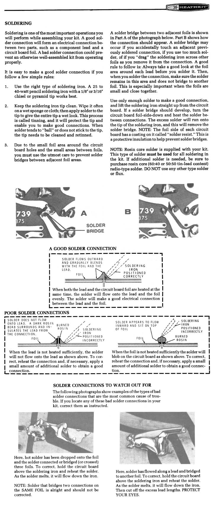
Soldering Basics. [Editor] If you need a soldering iron for electrical circuit repairs, buy one rated at 35-40 Watts which is adequate to heat small component leads. Use rosin solder specifically rated for electronics so the flux is compatible with the boards. How to Solder. Some good YouTube videos exist to help you learn how to solder: see especially How and WHY to Solder Correctly.
Soldering Tutorial. See also the excellent Heathkit discussion of soldering techniques for more information about how to solder electronic boards. [Tips from Jay Simkin] To reflow the solder around the pins on a circuit board:
- Use an electric soldering iron, with not more than 25 watts capacity (this limits risk of burn-out).
- On the underside of the board, where the tips of mounting pins stick through the surface, touch the tip of the soldering iron to each pin for 1-2 seconds. NOTE: The break causing the problem likely is too small to be seen with the unaided eye (even with a magnifying glass). Thus, treat all of the solder joints on the relay and the main connector, as if any one could be the cause of the problem.
- If any pin seems "dry", i.e., if it has no or very little solder on it, add a small amount of ROSIN core solder. Note that ROSIN core solder is NOT plumber's solder, which is acid core. Rosin Core solder is the only solder to be used on electrical/electronic work. Acid core solder should NEVER be used on electrical/electronic items: it will cause serious corrosion and ruin the device.
- If the solder does not take - adhere - to the pin, clean the pin with some fine steel wool. Be sure to remove any steel wool fibers (blow them away) before applying solder.
- Be careful not "to drag" solder between pins. That will connect pins, causing power to flow in undesirable ways, and possibly produce serious damage. If you put too much solder on a pin, clean the tip of the soldering iron with a damp cloth, and use the tip to attract and hold the excess solder.
- Clean off excess flux with alcohol or water and a brush to prevent corrosion.
Multimeter Tutorials. See various Internet examples of how to use your multimeter, including a good basic one at MyTractorForum.com .
[Editor] Several websites have online wiring diagrams of varying quality. These are all limited in scope; you should purchase, as one of your first manuals, an OEM wiring diagram green book from Volvo specific to your year and model.
- http://www.autoelectric.ru/auto/volvo/740/1989/740-89.htm for some scanned OEM wiring diagrams of selected 740, 940 and 960 cars.
- For a collection of wiring diagrams, visit www.dropbox.com sign in and download the appropriate files:
- the dropbox website is www.dropbox.com
- click log in and enter:
- username: volvowiringdiagrams@gmail.com
- password: turbobricks
- click on file tab "files" and you can upload or view them from there.
- http://www.volvowiringdiagrams.com for an extensive collection of aftermarket wiring diagrams
For a superb introduction to basic automobile electrical diagnosis using a digital multimeter and accessories, see Fluke Corporation's website reference at http://www.fluke.com/application_notes/automotive/beatbook.asp?AGID=1&SID=103
Wiring Fault Diagnostic Tips
[Tips from Import Car Magazine]
DIAGNOSTIC THOUGHTS
Wiring failures occur as open, shorted or short-to-ground (grounded) circuits. An open circuit, obviously, is a broken or disconnected wire. Shorted circuits occur when the insulation between two wires fails. Grounded circuits occur when a bare wire is allowed to touch the vehicle's powertrain, sheet metal or frame. As for narrowing diagnostic probabilities, let's remember that:
- Before wasting hours of expensive diagnostic time, test all fuse circuits with a DVOM or approved test light. Remember that fuses can fail without showing signs of an obvious burn-through. Since a loose or corroded fuse connector may also cause many intermittent circuit failures, thoroughly inspect and clean the fuse circuits before proceeding with your diagnosis.
- Most wiring failures occur at either end of the wire as a bad connection. Although splice failures inside the wiring harness are rare, some nameplates are notorious for splice failures. Technical service bulletins (TSBs) and Internet sources offer valuable insight to typical nameplate problems.
- Corroded harness connections cause most intermittent circuit failures. Simply unplugging the connector and applying an electrically compatible corrosion inhibitor will repair most connector failures
- When diagnosing intermittent failures, remember that suspect turn signal flashers, fuses, bulbs and relays can be replaced more cheaply than they can be diagnosed. When diagnosing an intermittent lighting failure, for example, I always begin by cleaning the bulb sockets and installing new bulbs. How much diagnostic time are you willing to spend testing a $0.98 light bulb that's nearing the end of its practical service life?
- Engine, computer and body ground connections should be checked first, especially if the vehicle has recently visited the collision repair shop.
- Keep in mind that most electrical systems, when left untouched, perform very reliably. When they do fail, the failure will be predictable, such as a bad current or ground connection, blown fuse and the like. Most predictable failures can be solved within a two-hour time block.
- On the other hand, the DIY mechanic "short-testing" a cooling fan switch or fuel pump relay can create a multiple failure with unpredictable consequences like burning a wire within a wiring harness. Obvious tampering should always create a red flag... Electrical "red flags" may include newly installed sound systems, electrical accessories, trailer brakes, auxiliary lighting and the like
- Many circuits serve more than one accessory or function. Years ago, for example, I found that a burned brake light fuse was caused by a loose courtesy light in the ashtray. Without a good magnetic short detector, the problem would have been difficult to solve since a relationship between a brake light and ashtray light isn't immediately logical or clear, to say the least. In other unlikely cases, I've found an instrument cluster fuse that also supplies field current to the alternator. The moral is, never rule out the effect of one circuit upon another
- In fact, avoid using test lights altogether. When testing fuses, for example, I use an LED-type test light (available from a major tool manufacturer) that indicates open or grounded fuse circuits and voltage availability. This eliminates guesswork and protects ground-sensitive electronic circuits like air bag sensors.
- Use a professional DVOM with a min/max voltage feature and alarm to test intermittent failures. The min/max feature will record the highest voltage reached in the circuit and sound an alarm each time a higher voltage is reached. For the technician working alone, this feature is a real time saver, especially when performing a "wiggle" test on an intermittent wiring problem. In the same sense, lab scopes are particularly useful to find loose ground connections. During a wiggle or vibration test, loose ground connections will show up as a voltage spike in an otherwise zero-volt lab scope waveform.
- Remember how hard it is to find the trim screw driven through a wiring harness hidden underneath a headliner? A good short detector will help you quickly locate concealed short-to-ground circuits. For about 30 bucks, it's a great time saver for you and your customer alike.
- Tips on Finding Open Circuits. An open circuit is the opposite from one that is "shorted", because it is similar to a cut wire that is not connected to anything. This can be tricky to find since in an "open" circuit, there is no electricity flowing to help you locate the spot with a meter or short finder. This diagnostic trick uses the car's radio and any device with a large LCD display like a calculator to find an open circuit, but only if the car's antenna mast is metal. Let's say the brake lights are inoperative due to an open positive feed from the brake light switch. You have already found the wire to be open somewhere by an ohm meter test, but you don't know where and would like to shorten the search. Before you go ripping the carpet and interior trim out of the vehicle looking for the broken wire, grab your calculator. Start by disconnecting both ends of the line (unplug the lights end and the brake light switch then consult a wiring diagram to make sure any other devices attached to that circuit are disconnected). Connect an insulated jumper wire between the antenna mast and one end of the offending wire. Tune the car radio to a quiet (unused) AM channel. Turn on the device you are using with the LCD display (like your calculator) and pass it down the offending wire. You will hear the "Radio Frequency" noise generated by the LCD display in the car's radio speakers as you pass the good sections of wire and will fade out as you pass the break. You can demonstrate this test by tuning any radio to a quiet AM station and passing an LCD display device over the antenna.
- Tips on Finding Short Circuits. See the Special Tools section of the FAQ for suggestions on tools capable of rapidly locating shorts in wiring harnesses
See the following diagrams for fuse locations in 740/940 and some 760/all 960 cars:
740/940 Fuse Locations 960 Fuse Locations
Relay Basics. For a good site explaining the basics of relays, see Basic Car Audio Electronics or ClassicTruckShop.com.
See the illustrations below left and middle to identify relays in 740/940 cars. Caution: relay locations vary by model, year, and market: to determine differences, use an OEM wiring diagram book. To access relays, remove the ashtray (push the spring clip at the top) and fuse panel cover (push the plastic snap at the bottom). Then remove the snap-on cover over the cigarette lighter with your fingernail or a small screwdriver. Remove the two philips screws securing the storage box: one of these is angled in. Remove the storage box by gently tugging on the left side, pulling it and the cigar lighter wire out from the console. Beneath it you will see the relay tray behind the fuses. For 760/960 cars, starting in the 1988 model year the relays are mounted under the left hand console panel, just the the left of the front passenger's left knee. Pull gently on the panel and it will unsnap. See the right illustration. Beginning in 1995, 960 cars have relays in the engine compartment and in the fuse panel shown above. 1994/1995 940 B230FD non-turbo cars using either Bosch or Regina have rather square, squat, blue-colored fuel injection relays in the front row, second from right.
Relay Removal.
[SGFM] Relays in most cars pull straight up from the relay base. However, in some 760 models (with relays located behind the lower dash panel below the stereo, facing the passenger side) the relays have retention devices. Two sides of each relay are held by plastic clips that must be pried OUTWARD at the same time to allow removal of the relays. Unless you accomplish this maneuver, you'll either break the relay or the retention device when forcing the relay out. I found that toothpicks wedged into each side retention device allowed the relay to be removed with the least amount of pain. In the 760/960 diagram shown above, A, B, F, J, L, and M are permanently attached to the board.
Air Conditioning Relay. [Inquiry] The 700/900 FAQ shows the relay cluster, but there is no AC or ACC relay shown on this panel. Where is it? [Response] Check your wiring diagram. If an air conditioning relay is fitted, it generally will be located behind the glovebox.
Relays and Fuses:
Fuel Injection Relay Applications.
FI relays can differ by model. According to the Pocket Date Book from Volvo, all F/T engines (both Bosch and Regina systems) through 1993 use the -608 white relay regardless of turbo/non-turbo. For 1994 and after, B2XXF NA-engines use the -270 relay and T turbos use the -608 relay. All E engines use the -639 relay. However, some 760 Turbos use the green 1362914 relay. Per John Marshall in New Zealand, some of the later 9 series (1994 onwards) have a different layout of relays and use a blue Hella fuel pump relay, mounted second from the right in the front row. The one to the right of it is the same Hella relay, used for high beam lighting. The Hella relays on have 5 pins in the base and are marked as follows: Hella 12V/ 4RD/ 003-520-52. Even a diligent search of Volvo Technical publications (e.g., the wiring diagram, that for other electrical equipment, etc.) will not show this change in the color, size, and location of this relay (versus the white, rectangular, second-row position, for earlier 940s). Note that relays are not interchangeable.
Relays and Fuses Overheating. Relays.
The fuel injection relay should not get hot even if the pump is drawing too much current...until the excess current starts to kill the contacts. Either way, a hot relay is a bad relay. There are three possible reasons for a hot relay:
- cold solder joint cracked
- bad crimp joint in the base
- bad relay contacts
Resoldering Internal Relay Solder Joints.
All mean that a point in the relay has resistance and when current flows through that point there will be a voltage drop which means work is being done and that work manifests itself as heat (P = E * I). Over time the bad joint gets worse due to the heat and maybe heat/cool cycles, the resistance goes up, the joint gets hotter, the voltage at the pump goes down so it needs more current to do the same work so the joint gets hotter, it gets worse, well you get the picture. At its worst this kind of scenario can destroy a motor because the low voltage condition causes a high current draw which over heats the motor. The relay may or may not be fixable. I usually try to fix them and am often successful. Note that Volvo released an improved relay, which has silver base terminals, to solve this problem. If the car's existing relay has copper-colored terminals, replace it with the newer relay. [Another:] Your description of the innards of the fuel pump relay sounds right.... the wires from the solenoid coils to the PCB are small and fragile -- but I've never experienced them breaking (at least, breaking from vibration). Because they're fragile, fingers off! Soldering the PCB is done on the other side from the components. You'll notice the component leads (including the fine wires) stick through and are soldered to so-called "traces". These traces are copper, but are usually completely covered by solder so have a silvery color. You'll also see where larger tangs stick through and are soldered -- these are the heavy-current leads from the relay contacts as well as the relay connectors. I usually solder the heavy connections using a soldering gun (but carefully, because these deliver a lot of heat quickly, and can damage a PCB). The smaller solder connections are best done with a small 25-35 Watt with an iron conical (pencil point) tip. Of course, you must use electronic solder, not plumbing solder (which contains an acid-based flux). Allow the iron the get fully heated before starting. Apply some solder to the tip and then wipe the solder off so that the tip is shiny. You can remove the old solder with a sucker or copper braid and re-solder by heating the heavier part first and then applying new solder. Or you can reflow the old solder again buy heating the heavy parts first and then adding a little new solder to get flux on the joint. Don't put a big blob of solder on, just enough to make a smooth joint between the component and the board. The finished joint should be shiny.
Soldering the Relay Base Crimped Connections.
I've seen several instances on 740s of excessive contact resistance at the fuel pump relay base connector. This causes overheating and melting of the spade connectors and plastic socket. It probably wouldn't hurt to examine the male spade connectors and socket for signs of high resistance and overheating (discoloration of metal, melted or burned plastic). [UK Club] The problem seems to be poor connectivity at the terminal end of the wire. Over time, the factory crimped wire and relay base connector increased in resistance and overheats. I eliminated the problem by soldering the wire and connector to correct or reduce resistance heat. Unplug the relay. Pull up the base and cut back the wire insulator just slightly. Prepare the surface areas and solder a bridge between your wires and connectors. You do not have to put on new crimped connectors. Re-insulate the exposed areas with a liquid insulator. Install the relay. Crimp Integrity. [Rick Taylor] After my wipers and heater stopped working, I took the fuse panel cover out and discovered that for the relevent fuse, Volvo uses one hot wire for three fuse positions. This single hot wire fed the blower, wipers and the SRS system fuses! It was loose under the panel and I re-crimped the contact to make it fit tighter. This seems to have solved the problem. 940 Electrical System Shutdowns. [Al Bert] If the car's electrical system shuts down and the battery cables and ignition switch are not at fault, check the relay/fuse panel mains and sockets, especially what may be a hot wire connected to the short buss below the sockets. Fuses 1 through 5 share a common battery feed; if this overheats or the sockets melt, similar symptoms will appear. Often this will be intermittent: when the wires cool down, the connection is re-establised. Burnt fuse and relay panels and overheated connections are common in used 740 and 940 cars.
Drilling Holes in Relay Covers to Cool Them.
Problems with the 740 fuel pump and headlight relays are well documented. Volvo has a tech. bulletin that recommends replacement of the relays and the sockets, which have both been done to my car before I purchased it. Driving today, I put my finger on the fuel pump relay and it was darn warm. I could just hold my finger on it - any hotter and I wouldn't be able to. Is this normal/acceptable? If no, what's the fix (another relay??). [Response:] Relays on Volvos run hot. That's why I drill holes in the covers. You must first remove the circuit board to drill the cover. On overdrive relays, I have never had to replace a relay with holes in it, it seems to help a lot. I have also run cooling to the relay/fuse board from the crotch cooler port, so when the A/C is on, it blows cool air on the board via hose. It may help and can't hurt.
Socket Integrity .
[Bob Kraushaar] If a relay/fuse is not firmly set in its socket, a poor contact can result, which results in overheating and melting plastic. If the plastic holding the wire connectors melts/softens enough, the connector can be pushed out of the retainer and make contact with nearby wires or metal parts. This, in fact, happened to my headlight relay with resulting smoke and intermittent light failures.
Relay and Fuse Panel Removal and Replacement .
Preventive Maintenance. [Jim McDonald] Relay and fuse connectors carry a great deal of current. Removing and reseating the fuses and relays every couple of years will ensure that the connections are seated and will also diagnose loose connections prior to failure. Look for evidence of burned fuse or relay holders when you do this.
Removing the Fuse Panel. It is possible to pull the whole relay panel out the front of its opening. Use a good light so you can see well. First remove the plastic storage box (which also contains the accessory socket) above it to facilitate this. The trim around cigarette lighter will pry off to reveal two screws, one going straight in and the other going in at a 45 degree angle. Put your hand below the screws as you remove them as there is a great likelihood that the panel nuts into which the screws are secured will fall out when the screw is pulled out.
To remove the relay tray beneath, look for the white catch on the left towards back of relay panel (back meaning towards back of car). Push this to the left and then lift the relay board up at least 1/2 inch before the tray is pulled rearward and out. If the tray does not side out toward you, the plastic tab might be catching on a side lip of the fuse tray or the spliced and bundled electrical wires running to the back underside of the tray might be catching. Pull gently to allow the wire bundles to unflex as they are removed. The opening in the console is just the right size--the tray does not need to be turned or twisted.The wire umbilical attached to it is long enough to allow the panel to be pulled out quite far. This is also how you can hook up accessories to the fuse and relay connections under the panel.
 Replacing the Fuse Panel. [John Sargent] If the airconditioning and heater fan are used much, all 1984-87 760s, and all 740s and 940s (not the 940SE) will eventually wear out the fuse holder for these functions. It is fuse 14 on the early 700 series, and fuse 16 on the later 740s and 940s. The heater fan and AC quit working at all on my daughter's 1987 744T, and the fuse block looked like this. Fuse holder 16 is melted.
I was originally going to bypass fuse 16 with an external fuse holder, but this fuse block was so bad I decided to replace it. Replacing takes a little more time but it isn't hard to do. Get a good fuse block. Disconnect the battery ground before you start. Remove the ash tray, fuse cover, cubby hole, and radio. Then you can lift up on the Central Electric Unit, pull it towards you, and turn it over. Yes, the wires are long enough. They were made to do this.
 Once the CEU is out and turned over, this is what you will see.
Everything is color coded to its location. The supply wire for each fuse is in the plastic socket,and is marked with a wrap of black tape. Remember this. Some supply wires feed more than one fuse, as the fuse supply sides are connected inside the fuse block. The supply wire for fuse 16 also supplies fuses 14 and 15 on this car. If you are uncertain, take a picture with a digital camera before you start removing wires.
Once the wires are removed, use a small screwdriver to raise the black plastic over the three lips on the front of the fuseholder. When re-installing the wires, be sure to push them all of the way onto the spade fittings. I use needle nose pliers for removing and re-installing the wires.
Relay Tray Removal and Replacement. My headlight relay got into a bad habit of getting real hot. I had the same problem and after replacing the relay, I replaced the plastic base. It's quite easy, get yourself a Volvo part1307160 (CAD$2.89) and pull your relay/fuse tray out of there. After removing the relay, flip the tray and remove each wire (tape the lug & mark the position). You can usually coerce any crimp-on connectors out by bending the little tab internal to each connector (with a small screwdriver).Once the relay base is clear of wires, unclip and push it out. Install your new base and re-install each wire in the proper position. With crimp-on connectors, you can use a knife to "restore" the little tab on each crimp connector so that it "clicks-in" when you re-install the connector in the base. I find that, It is vital to have firm connectors or else they slide out when you push-in your relay! One additional note... The base melts because there is resistance & arcing between the crimp-on connector and the relay lug. There is quite a bit of current going through there and you want to make sure that you have tight connections. You can do that by "squeezing the gulls" of each crimp-on connector. Contacts #30, 87 & 87b are the culprits (not sure if they are all used though). My relay panel is all plastic. Double-check the part number of the relay base by removing a relay and reading the part number in the center of a "good" relay base.
Crimp Failure. Note that cases of relay or fuse panel socket connector failure have been traced to the crimp on the wire. To solve this, solder the connector to the wire and re-insulate with liquid electrical tape.
[Inquiry] My 1984 740 Turbo has a melted fuse that protects the heater blower/ac circuit. The fuse did not blow, but instead heated up enough to melt the fuse and the surrounding fuse box. Suspecting a short to ground fault within the circuit, I have examined the wiring and do not visually see any bare wire. I have replaced the blower motor, relay, and the fan motor switch without solving the problem.
[Response: John Sargent]This can be fuse number 14 (early 740s) or 16. The fuse and fuse holder are simply overloaded in the basic design. There is too much current draw on the fuse holder. It was fine when new, but too many heating cycles weaken the grip of the fuse holder on the fuse after 15 years. This is a very common problem on 700 series Volvos. Unless your car has over 200,000 miles on it, the only part of the central electrical unit that will be bad is the fuse holder for fuse 16. Nothing lasts forever, but fuse 16 is the weak point. The wiring to the CEU should be fine, although high mileage cars can have troubles at other relay sockets. You have two choices:
- Replace the entire fuse block panel with a new, or good used unit.
- Buy a new fuse holder and power the AC and heater with it
If you choose option 2, you must pull the central electrical unit out and turn it over. Splice a fuse holder into the lead supplying power to fuse 16. Splice the load side of the new fuse into the black lead supplying power to the heater and AC unit. You must continue to supply power to fuse 16, as fuses 14 and 15 are fed from the supply side of fuse 16. It is possible to intercept those black wires elsewhere, but it is easiest for me at the CEU. If you can get enough slack in the black wire which supplies fuse 16, a red wire nut works great for spicing the new fuse holder in and keeping fuse 16 supplied with power. The fix will be less than $5 US.
Fuse 5 (Clock, Etc.) Failure Diagnostics.
[Tip from R. Duke] I had the classic symtoms of a blown fuse #5 due to a short - lost power to clock, etc. The "ding ding" indicator signal was also constantly sounding. It looks like one of the most common causes is the courtesy/dome light. The circuit board in it can develop a short. The circuit board contains the timing circuit for leaving the light on after you enter the car until you have time to put the key in. Apparently this part has gone through several updates. The internal parts are quite different on the updated one. The new one cost about $78, but it does come with the lenses and bulbs. It actually works better too (better switches). Volvo has a parts bulletin about the change. The new one has a different connector and you are supposed to crimp new pins on each of the 4 wires (Volvo can supply those too). Those pins are hard to crimp unless you have the correct crimp tool, so I just soldered 4 jumper wires on to the circuit board and used insulated spade connectors on the jumper wires to attach to the 4 supply wires. If you ever get this problem. Pull the fuse and take a reading to see which side of the fuse holder has 12 volts on it. Then take an ohm reading from the other pin to ground while you look for the short. That is easier than blowing a bunch of fuses. There are a lot of devices on that fuse.
Repairing and Resoldering Relays.
Here's a generic statement about your relay -- this statement displays my bias about the poor quality of  Bosch wave soldering. If you can pop the cover off the relay using a small screwdriver to pry the cover at the edge, try resoldering all the connections on the circuit board before you replace it. (After all, you have nothing to lose but a few minutes.) The heavy connections that go to large components like the actual relay may need a large soldering iron or gun, whereas the connections at smaller components, such as transistors, should be reflowed using a smaller iron, like a 25-Watt iron. Use rosin-core electronics solder. If you're not comfortable soldering, find a friend who is.
[Don Foster:] Over time (like 10 years), the solder used in production manufacturing tends to become crystallized and cracks. The type of solder used in high-volume production is different than that used in an electronics repair shop. The problem with the relays is tiny, almost invisible  microscopic cracks in the solder. These cracks usually encircle one (or several) heavy connections
 , such as from the relay or a main lug connector. Under a bright light, and using a magnifying glass, inspect the soldered connections. Don't forget to look for broken conductive traces as well. Simply resoldering these circuit board very often restores them to perfect performance, and it's a whole lot better (and cheaper) than a $50-$100 replacement part. I have recovered literally dozens of Bosch relays (OD, fuel pump, wipers) to perfect performance this way at $0. In fact, I resoldered ALL the relays in my family's 6 Volvos before a failure stranded us. The illustration shows an overdrive relay with solder cracks. Not shown is a broken trace (discovered with a magnifying glass) at the top of the board, repaired with a soldered jumper wire [courtesy Don Foster] [Murph] It's very helpful when resoldering a relay to treat the pins with some Caig "ProGold" or "Gold Guard Pen". It can go a long way in preventing oxidation. Easy to apply & no waste, but expensive. Any good electronics parts shop will have it
Soldering Tips and Techniques. [Don Foster] See the excellent Heathkit discussion of how to correctly solder circuit boards and contacts as well as Jay Simkin's tips below.
Overdrive Relays. See the photos above. Bulb-Out Relay. [Randy Starkie] my experience is that the most common failure is one of the joints easily accessed at the top of the unit once the cover is removed. If you can't see the bad joint just simply resolder all of them at the top. [Matt Evans] THere was a bad solder joint on the middle circuit board that I was able to re-flow without disassembling. Other Relays. [Ed Lipe] Relays fail the same way in any early model vehicle: solder joint cracks on the boards. Keep this in mind when you have intermittent problems with any of the relays in your car. Bulb Failure Relay. See the notes below for solder joint failure points.
General Diagnosis. The bulb-out relay senses differential current flows to paired lamps to detect a bulb failure. If it senses a bulb failure, it illuminates the instrument panel warning lamp. However, if the relay itself fails, then the brake lighting circuit (among others) will fail completely and the cruise control will also cease operating. Advice: carry a used but working spare unit.
[Inquiry] The brake lights on this car don't work. The fuse is okay, there is power at the brake pedal switch and the switch works. I get no continuity, power at the white junction block leading to the rear harness. Could it be the bulb failure relay itself or is there a little rats nest in there somewhere. [Response: John Sargent] The brake light failure in our 87 745T was caused by the bulb failure relay. You may be able to re-solder, or you can replace it. The bulb failure relay is in the front left corner of the relay plate, and is red and round. [Self-Diagnosis from Guy Jett] It was the bulb out relay. The counterperson at the local Volvo dealer said "Oh yeah, they go out all the time." Note on diagnostics. It was helpful to disconnect other bulbs and see that the bulb out relay still was not working. I think I will keep a bad bulb or two in the future for such testing. [Jason Kneier] I opened the bulb failure relay up and traced the path the brake light circuits took (pins 54R and 54L on the base of the relay). I saw two suspect solder joints, both of them 'bridging pins' that connected between the three boards, and so I resoldered them and put the relay back in - Success! [John Sargent] The solder joint on the board leading to contact 9 (brake light circuit) can fail; resolder this to repair it.
Headlamp Failure:
[Inquiry] Driving headlights only work when high beams are selected. Please help. [Response: John Sargent] Are your low beam fuses okay? If they are (and they probably are) you either have a bad high/low switch (unlikely), or a bad Lamp Failure Relay. The Lamp Failure Relay supervises the Low Beams, the Tail Lights, and the Brake Lights, but not the High Beams. Lamp Failure Relays do go bad. Remove the Lamp Failure Relay from it's socket, and test for voltage at the pin connection for terminal 56b, which is one pin clockwise from the pin socket labeled S in the relay base of the Central Electrical Unit. Terminal 56b is the output for low beams from the high/low switch. If you have voltage there, the high/low switch is good on low beams. Re-install the Lamp Failure Relay and test for voltage at the input side the the low beam fuses. If you don't have voltage there, the Lamp Failure Relay is bad. You can pry the cover off and attempt to re-solder it or get a used one. The headlight relay is energized by the light switch and supplies current to the high/low switch. If it was bad you would only have high beams when pulling the high/low switch towards yourself. In this momentary position, the current for the headlights comes from fuse 2.
Engine Wiring:
Removing Engine Wiring Connectors and Ties .
[Inquiry] What's the trick for removing the Bosch connectors with the wire spring retainers? I know I'm missing something simple here... [Response: R Haire] Depress the spring toward the connector to release the locking action, then pull. It can be frustrating with oily fingers groping under the manifold for the right pinch.
Releasable Wiring Ties. [Carter] The releaseable ties that attach to little posts along the firewall and elsewhere in the engine compartment are Volvo part number 969019/ product number 489492-001 costing about $7.50 for 10.
Baked Engine Relay Connectors.
New Connectors. [Tip from Dick Riess] Son's car decided to have some relay problems. Wasn't the relay, but the plug-in ends had turned to mush. After chasing my green manuals, I found the answer. These are in
 - stock at Volvo. They are terminals, the insulated kind that insert in various grey connectors, including relays, wiring harness hookups and fuel pumps. These are complete with a pigtale so they can be soldered or crimped together. Volvo number is 3523813-8. Suggested retail is 5.29, got mine for 2.95, so they are reasonable.
Install Insulated Tubing. [Lewis King] After a prolonged diagnosis procedure ensuing from a no- start situation,
I foundthe root-
start situation,
I foundthe root- cause to be rotted insulation around the inside
connectors to my Radio Suppression relay (relay p/n 3544322). Despite
swapping the relay with a known-good unit, I was unaware the connectors
weren’t actually making contact because they had slipped down inside the connector body. Heat, time and vibration had taken their toll. Have since found the same issue on the Aux Fan relay connector. Instead of Dick's repair above, I pursued an alternative solution that was cheap. The repair is weather tight and did not entail
cutting/crimping in new wires or soldering. As the photo shows, I used
aquatic tank AirLine tubing procured from a pet supply store (Petco SKU
1446614-8FT for $5 USD). The inner diameter is just right to hold the
female connectors yet small enough to make a tight fit around the base
of relay pins (what found at local hardware stores was too big). The hose was cut to approximately 1-1/4inch length to fit lengthwise
inside the connector body. The 1/8 inch of gap between the female
connector and tube end seals around the base of the relay pins when
connected/ making the weather seal. The aft end was filled with JB Weld
to seal and keep the wires from shifting inside the tubing. After a
day of drying, I routed the wires through the bottom end of the
connector body and then reconnected each wire individually to the relay
pins and then shoved relay onto the connector body. All is well – car starts.
cause to be rotted insulation around the inside
connectors to my Radio Suppression relay (relay p/n 3544322). Despite
swapping the relay with a known-good unit, I was unaware the connectors
weren’t actually making contact because they had slipped down inside the connector body. Heat, time and vibration had taken their toll. Have since found the same issue on the Aux Fan relay connector. Instead of Dick's repair above, I pursued an alternative solution that was cheap. The repair is weather tight and did not entail
cutting/crimping in new wires or soldering. As the photo shows, I used
aquatic tank AirLine tubing procured from a pet supply store (Petco SKU
1446614-8FT for $5 USD). The inner diameter is just right to hold the
female connectors yet small enough to make a tight fit around the base
of relay pins (what found at local hardware stores was too big). The hose was cut to approximately 1-1/4inch length to fit lengthwise
inside the connector body. The 1/8 inch of gap between the female
connector and tube end seals around the base of the relay pins when
connected/ making the weather seal. The aft end was filled with JB Weld
to seal and keep the wires from shifting inside the tubing. After a
day of drying, I routed the wires through the bottom end of the
connector body and then reconnected each wire individually to the relay
pins and then shoved relay onto the connector body. All is well – car starts.
Baked Engine Wiring: 700/200 Cars.
[Early-80s to 1987 240 and 7xx cars:] Harness failure often causes multiple symptoms such as rough idling, stalling, hesitation, overall erratic performance and random misfiring. The symptoms may mimic ignition or fuel injection trouble you've encountered on other cars. I cannot address 240 vehicles newer than 87, the friends I help do not own anything newer. In all the 240's I've seen there are several wires that are "flaky": oil pressure; alternator wires and alternator dash signal; knock sensor; water temp gauge; starter from ignition; starter to coil; primary ignition wiring near the ignition coil; and on 7xx cars, harness connectors in the right rear corner of the engine compartment below the ignition coil. ALL the wires from the ECU do not show any signs of deterioration in any of the harnesses we have opened up. Since the flaky set are wrapped into the main harness to replace them means replace everything. At big $$$ for Volvo & the service center. After getting nailed for the 85's harness, I took preventive measures on my 83 and others until we find a long down time to correct the problem. We replaced the alternator and the oil pressure sending wires rerouting them around the right side of the engine bay. We believe that if the alternator wire shorts to some other wire that is where the big problems could occur. The alternator wire has the potential to supply a constant 12+ volts to any of the others ( which are to ground) and act as a heater wire inside the harness, getting hot enough to melt all the others.
In my 85 it was from the starter wire to the alternator wire up by the dash connector and was caught before much damage was done. Had it replaced by the dealer thinking insurance only to find that insurance refuses to cover this problems in Volvo's. Cutting open that harness revealed NO damage or deterioration to any other wires in the harness except the above wires. Our solution: We reroute with new wires to all of the above sensors. Best done with some other time consuming task. To make it really easy we release the intake manifold. Takes two of us about 3 hours to reroute all wires and replace the manifold. Tried it first without releasing the manifold and it took 8 hours. I believe Volvo could have created a replacement harness consisting of just these wires but did not do so because of $$. Another is that if you catch the problem soon enough no other wires will fry because of a short between two of the bad wires. Wait too long and other wires will be damaged from the heat of the short. Since this is probably about the time Volvo found out about the problem, it looked to them like all the wires in the harness are bad. See Dave Barton's extensive discussion of wiring harness woes.
[Quick preventative:] Watch the wires coming from the connector directly under the windshield below the driver and the oil pressure and alternator wires on the right front of the motor. These are the first ones to go. If it starts reroute the alternator wire first as this can cause the most damage if left in the harness. Then replace the starter, then the coil wire as these have the next greatest potential for damage. If you can, get the wires replaced before they cause other damage, do so as the cost will come out of your pocket.
[1983-1987 7xx cars:] If you are referring to the problem of wiring harness rot that affects the 83-87 models, it usually affects the harness on the engine. On the LH cars, this usually includes a fuel injection harness and a separate ignition system harness. However, I have seen some deterioration of other underhood harnesses including the wiring that goes to various lights (turn signals, corner markers, headlights, etc.
[Advice on replacement:] The engine wiring harness went bad on my 1983 240 Turbo (170,000). I noticed it first when my starter would try to engage occasionally when I hit a bump or turned a hard right. The wires up by the firewall on the left side of the car were bare at the connector. I tried to separate and tape them, but that did not work. I found out why when I replaced the harness. The harness runs along the left side of the block, and EACH of the wires was completely bare the majority of the length of the block!! As you know, depending on which ones touched which, anything could happen. REPLACE the whole harness!!!!!! Trying to patch it will only lead you into hours and hours of nightmares both as you attempt to cob it together, and as soon as moisture gets in your cheesy butt connectors and your gauges, idle, starter, etc go wacky!!!
Remember: My Volvo is Turbo. Although a similar process, I can not speak directly on the naturally aspirated version. The job took me (a former diesel mechanic but working with limited tools on this job) 5 hours. I unbolted the intake and pulled it away from the head. Of course to do this you will need an intake gasket. I recommend you do this also, as to work around and under the intake would be treacherous. With the intake pulled away, you can see straight down in there. You may want to replace your flame trap when you are in there as you have a straight shot at it. Any troublesome vacuum lines could easily be swapped out also.
The new Volvo harness is color coded exactly as the original. (big advantage). It is also exactly correct in length. (huge advantage). Just remove the old one, being careful at each connection - temp sensors, alt, oil press, etc. are all very dry. You may have to cut the old harness out in pieces as it is not pliable at all. Install the new one by starting at firewall and working your way along the block and around to the oil press and alternator. It is pretty self explanatory really. Leave about 5 hours to do it. This sounds like a lot, but multiply it times the hourly rate of your local shop, or the cost of burning up a starter (and a tow) like I did, and you will have a little more incentive to clear up some time on Saturday morning. No special tools. (May want torque wrench for intake if you are REALLY particular). I shopped all over and I purchased it from NILS SEFELDT Volvo in Houston Texas (281) 721-1600 (800) 468-0041 for $230.22 and the gasket for $11.70.
[Additional tips from Dick:] My suggestion: do not remove the intake manifold on the 700 series. Remove AMM and hose to intake, idle speed motor and hoses, also flame trap and oil trap. Label stuff carefully. Begin your rewire from under the car, ie the oil pressure sender light, removing the old stuff as you go. Your new harness has yellow bands indicating where the clamps should be. Remove the harness from the AMM and replace with new. You will have to remove the knock sensor wiring and mark it . I think you get the picture. With the oil trap removed, you can clean it and put a new O ring on it (leak source) and new flame trap. Other suggestion is to remove the 3 plug ins on the passenger side and pull then through and under the manifold along with the injector harness stuff.
Believe marking and labeling is extremely important. I blew the brains out of a 240 by mixing up two similar 3-prong connectors. Label the old harness too because you can always compare wire colors in the connectors that are alike.
[More from a VCOA Wiring Clinic, courtesy of the BrickBoard:]
Scope: The problem afflicts 200 and 700 series Volvos manufactured during the period 1983-1987 [Note: several commentators would also include the 1981 & '82 models of 240 series.]. The problem has also appeared in other vehicles manufactured during the same period with Bosch electrical systems. Owners of all vehicles manufactured with Bosch electrical systems during the period should inspect the engine wiring harness. Anyone considering purchase of such a vehicle should inspect the engine wiring harness if the harness is the original.
Presentation of problem: Disintegrating insulation on wires exposed to high temperatures for long periods (10 years or more).
Symptoms: All vehicles within scope are vulnerable to the problem. Close inspection of the engine wiring harness will reveal the problem before it causes short circuits. If a vehicle within scope exhibits drivability problems that are intermittent and cannot be otherwise diagnosed, short circuits in wiring harness caused by deteriorating insulation may be the cause. Connector bodies can also deteriorate.
Inspection: Use a strong light source and check wiring, paying particular attention to wiring passing close to high heat sources. High heat sources include intake manifold, exhaust manifold, turbocharger, block, firewall.
Common locations presenting problem: B23: firewall near main connector, alternator, intake manifold. B230: ground wires on intake manifold, oil pressure sender, water temperature sensor on block. B28/280: no engines were available for inspection.
Solutions:
Temporary solutions: liquid electrical tape, applied in several coats over several hours, good between -20 and 255 degrees F; shrink-fit insulation, applied with heat gun or torch, good past 400 degrees F, but hard to fit correctly over end connectors; spliced wiring, recommended by some Swedishbricks and SAAB list members as the most nearly permanent fix that does not require a new harness. Standard electrical tape is at best a one-month reprieve. Any solution short of splicing lasts no more than a few months.
[Editor] Normal PVC-insulated wire, used as a replacement, will not last long in high underhood temperatures.
[Tip from Jim Bowers] DO NOT use teflon insulated wire around your car. While it has the best high temperature rating it is notorious for "cold flow". Where it is bent around a corner the insulation will eventually "flow" out of the place where the pressure is and it will short. Kapton is a another high performance insulator that is so good in tests, that it passes the tests with very thin dimensons, saves space and weight. However, over time vibration can wear through the stuff. It has superior mechanical, temperature and radiation properties. "Flex" circuits are often made using it as an insulator. Its "natural" look is orange and semi-transparent. Its so $$$ that it isn't used often. After considering everything, irradiated polyolefin is a good choice.
[Tom Irwin] It may be best to get a good one from a wrecker and graft new sections onto the rot. 1" strip and a union twist in the wire. Silver Solder and a 1,200 degree iron. FLOW it in there. Use a 3M product "self-sealing silicone wrap" used for field repairs on high power lines. Stretch it til it just about tears and wrap your wires tightly. As it heats and ages it melts together and forms a tough, conformal coating. Stuff it in a split loom and tie wrap it up.
Permanent solution: new wiring harness, cost ranges between $250 and $350 (US). VCOA has been successful in persuading Volvo to lower the price of its wiring harnesses for vehicles within scope, and current price range quoted above reflects those reductions. Prices have been cut from 33%-50% from previous levels (Example: old price of engine harness for B230FT engine was approximately $500, now reduced to $270). Dealers who offer club discounts will add their standard discount to the current prices. It is absolutely critical that you order the correct harness. Very difficult to do when there are 3-4 variants out there, yet little way to tell the harnesses/engine applications apart.
Labor Requirements: Owners who prefer to have a mechanic install the new wiring harness can expect to pay 4-6 hours of shop time for the job. Owners who prefer to do the job themselves should set aside one or two days. For the B230 engine, it is recommended that the owner have all vacuum hoses replaced at the same time, as well as fuel injector seals. In addition, performing the job on the B230 engine involves removal of the intake manifold and air intake valve, and so requires replacement of the intake manifold gasket and the air intake valve gasket. Owners who have replaced wiring harnesses of B23 and B280 engines may wish to offer advice on other maintenance that should be performed at the same time, as well as other parts (besides the wiring harness) that may be required. Dielectric grease for multi-pin connectors, as well as an oxidation inhibitor for single connection points to aluminum ground, are recommended. Do not interchange the two, as dielectric grease is an insulator, while oxidation inhibitor is a conductor.
Picture References. Check out http://www.homestead.com/volvo2/harness.html
for visual images and instructions for wiring harness replacement and other maintenance items. See Dave Barton's excellent site for details on the harness problems.
Replacement Procedure:
[Dick Riess] For those feeling threatened by this job, it can be done relatively easily, in my case under 4 hours of puttering slowly. Also, a good source is Dave Barton and his super choice used harnesses.
- Unhook the ground battery cable.
- Remove the intake hose from the AMM to the throttle body.
- Remove the idle speed motor, sliding it out of its holder. Hoses too. Remove top portion of flame trap and hoses.
- Jack up passenger side of car and remove splash pan. Remove oil pressure wire--a push together clip. Remove the two 10 mm nuts and clips holding the wire under the engine. Take clips off wire. Label all wires you remove---DO IT!!! You can screw up.
- Remove the two wires from the alternator. Detatch the blue ground as it will be easier to work in the area.
- Unhook the inline connector to the AC compressor--easier to work in area. Remove clamp holding wires to the manifold-engine brace--10 mm.
- Remove the top 10 mm bolt holding the power steering reservoir and loosen the bottorm one. Now lay it toward the firewall. Trace the wires from the engine and you will find another clamp on the fender well that needs to be removed, 8 or 9 mm I think. Unplug the large gray connector and the AMM connector.
- Lay out your new harness and get acquainted with it and lable connections. Now start to remove the old harness toward the engine and start to plug in new stuff. This is a real mess of wires and connectors, but your labels help.
- Remove knock sensor plug and temp sensor (gray). Knock sensor wire is not replaced, just easier to work with it out of the way.
- Remove the two wires on the starter, remembering (write it down and label) what goes where. You will need to clip a number of black nylon cable zips along the way. Unplug the coolant sensor by the heater hose inlet on the block. Clip more zips. Go along the fire wall and try to unhoop the black zips---they will probably break. Now you can remove the harness from the engine area and install the new. Look carefully at the routing of the harness around the flame trap and dip stick.
- Remove the two large phillips screws holding the coil in place, lay it toward the center of the engine bay. Clip the zip holding the two large gray plugs and remove the one wire from the coil. After removing more zips you can remove the old harness and replace the new. Install new zips where old ones were. Recheck and reinstall things as they were.
This is a good time to service oil and flame trap area if needed. The main thing is to make drawings, write things down and lable harness ends, both old and new.
Baked Engine Wiring: 960/90 Cars
See the notes in the 960 section regarding deteriorating wiring harness connectors near the coil packs in 960 six-cylinder engines.
Running Wires From Engine Compartment to the Cabin. [Inquiry] I need to run wires through the firewall into the back of the instrument panel. I notice that where the main wiring harness goes through the firewall, it's encased by a large rubber plug. Along the edges of this large rubber plug, there are two or three smaller rubber teats that stick out, with caps on them that look like they can be cut off. Can these be used for running extra wiring through the firewall?
[Response] Those extra "teats" are for wire passage through the firewall. Cut the top off in the engine compartment, fish the wires through, and seal the gap with a little silicone caulk. To reach the instrument panel easily, use the rubber caps right behind the strut tower: this opens near the hood release on the other side, and wires can be easily strung to the panel.
Grounds and Circuit Repair:
Maintaining Engine and Chassis Grounds.
Maintaining 700/900 Chassis Grounds:
[Inquiry:] What do I have to do to keep the grounds in my chassis circuits in good condition? [Response 1: Steve Ringlee] This is tough to do without the pictures in the Volvo OEM wiring diagram book (the best $25 I've ever spent, by the way) but here are the grounds for my 1990 745:
- Battery chassis near the battery: frequently corroded
- Engine main ground under the p/s pump (typically OK because of oil coating)
- Engine ground straps from the distributor and intake manifold to the firewall: crimps can loosen or corrode
- Right auxiliary chassis ground (behind right headlamp): frequently corroded
- Left auxiliary chassis ground (behind left headlamp): frequently corroded
- Inside left A-pillar: underneath the trim panel by the bottom front left door hinge; damp carpets can corrode this
- Inside right A-pillar: just beneath the engine computer by the right front door pillar; this is important since so many functions ground here and humidity/salt can affect it from the carpets.
- Left and right taillight grounds; often corroded and a cause of malfunctioning rear bulbs
- On the right console between the seats: usually not a corrosion area but the strap to the transmission can corrode
- Courtesy lamp ground above the left B-pillar; usually not a problem
- Fuel pump and sensor ground next to sending unit on fuel tank: frequently corroded
- SRS ground beneath the driver's seat next to the crash sensor. It goes without saying that if you are going to touch this, you need to disconnect the battery negative and wait some time for any charge to dissipate from the crash sensor.
- [Don Willson] Injector ground wires on the intake manifold: frequently corroded. Just cleaning them and tightening the bolt is not enough. The wire must be soldered to the crimp lug. The internal resistance of this crimp increases until injectors start to missfire, the O2 sensor sees too much oxygen and feeds the engine much too much fuel. Mileage drops to 10 mpg with smoke and no power. Check the main engine grounds at the firewall as well.
- Regina Equipped Cars: Follow the black coil ground wire to the harness near the right headlamp. If you are experiencing missing or performance problems, clean this ground.
These grounds, if corroded, can play havoc with your car's electrical system, including causing the loss of engine computers and ignition amplifiers. A lot of the problems brought up in both Brickboard and Swedishbricks forums relate to faulty ground connections. It pays, especially for those in wet or salty climates, to clean and de-oxidize the ground connections (DeOxIt from Caig Tools is great, at electronic stores) then coat them with OxGard conductive paste (get it at Home Depot) which is designed to protect electrical connections where conductivity is important and shorts across circuit connectors are not a problem.
Overall Discussions of Ground Fault Problems:
For a good overall discussion of Volvo electrical system grounds, see the article "Volvo Electrical System Service: In Search of Good Grounds", Bob Kraft, ImportCar magazine, December 1997 at http://www.underhoodservice.com/ (see their searchable archive for ImportCar Magazine.)
Ground Diagnosis. [Tips from Mike Dale, Motor Magazine, Jan 01] Many devices achieve their electrical connection to ground by way of a bolt or screw attached directly to the frame, body or drivetrain. As in the ring terminal example, the integrity of these grounds is dependent on the quality of the mechanical connection. There are several basic problems inherent in achieving reliable grounding. First, there's the issue of the mechanical connection itself. As an example, take the typical tin-plated brass ring terminal. This is crimped on one end of a wire to be grounded and fastened to the body by a self-tapping sheet-metal screw. Think of all the things that could go wrong with such a connection: The crimp to the wire could come loose, corrode or become mechanically damaged in a collision. The sheet-metal screw could back out as the body flexes during use and thermal cycling. The terminal and the place on the body to which it attaches could corrode due to salt, water or other corrosive fluids such as battery acids.
While identifying ground-related problems is not necessarily easy, there are some scenarios that should automatically raise a red flag. Multiple, seemingly unrelated failures are often ground-related issues. Mysteries such as the dome light flashing in unison with the turn signals are often fuse- or ground connection-related. Sensor outputs that are either out of range high or a constant value can be an indication of a ground problem. Poor performance of power loads such as the starting system, solenoids and fan motors may be the result of a poor ground connection, as well.
Analog sensors are much more susceptible to ground offsets and electrical noise in the system. The output of these sensors is often low (oxygen sensors, for example) and any loss due to poor connections can result in misinformation being sent to the computer.
Finding bad grounds is not always easy. Often, those sheet-metal screws I mentioned earlier can be buried in places that have never seen the light of day. Connections that look terrible may actually be okay, and vice versa. Just finding the location of a ground sometimes can be an all-day affair. Fortunately, much of the newer service literature does include ground location information. Once you've found the connection point, there are a couple of things you can do to check ground integrity. One is to attach one lead of a DVOM to battery negative and the other lead to the ground lug, ring terminal or metal body of a grounded assembly. When you operate the device, there should be less than a 1-volt drop across the connection; 100 millivolts is better, especially if it's in a low-voltage computer circuit. You can do much the same with an ohmmeter if the circuit is not powered up. What you're looking for is pretty close to a zero resistance connection.
Straightening out a bad ground often can be accomplished by simply loosening a screw or a mounting bolt, then retightening it.
In those cases where the integrity of a ground remains in doubt, there is something else you can do as either a diagnostic technique or as a permanent solution-hook up a redundant ground. To do this, attach one end of a wire to a known-good grounding point, such as the vehicle body or the negative side of the battery. Then bring the opposite end to the body of the grounded part or to the ground terminal in the connector to that part. Assuming that the wire doesn't get tangled in some moving part, the very worst that can happen is that nothing will happen. If the problem really is a ground issue, the wire may confirm the diagnosis or, when properly secured, be a permanent solution.
The key to identifying and fixing ground problems is to remember what the ground system does. It provides the return path for power and information distribution and forms the reference that voltages are measured in relation to. When your diagnosis says that neither of those two things is happening, it's time to go hunting for that bad ground connection!
Note: for intermittent driveability problems, see the section on de-oxidizing engine wiring connectors in the Performance section of the FAQ as well as brief notes on engine ground straps.
Using Dielectric or Conductive Grease to Protect Connectors and Grounds.
[Inquiry:] You have repeatedly recommended the application of dielectric grease to underhood wire connections. Isn't the insulating property of such grease counter to the goal of IMPROVING the integrity of electrical connections? I would think that a conductive paste (such as Eastwood's Kopr-Shield) would be better. The only potential downside I can think of is that sloppy application could cause short circuits, but care and common sense should preclude this.
[Response:] This is a good question and one that I have received several times. Yes, it is true that the dielectric grease is non-conductive. However, in the context of connections that carry voltages larger than 1 volt, the grease will not result in a bad connection. The male and female connectors will wipe enough of the grease off at the mating surface so that the electricity will flow just fine. The important part is that there is no chance of the grease creating a conductive path between adjacent terminals in a multi-terminal connector. The main purpose of the grease is to seal the terminals against oxidation which creates a high resistance barrier and moisture and dirt which can result in shorts and ground paths. CAUTION: DO NOT do this to any SRS/Airbag/Seatbelt connectors: these are all gold-plated and do not oxidize. If they get dirty from spilled drinks, etc., just clean them with a no-residue cleaner.
It is important to note that on all Volvos, the Oxygen sensor signal lead carries a very low voltage (0.2v - 0.8v) and the dielectric grease must NOT be used on this lead as it will interfere with the signal voltage.
For the GROUND connections - especially those in the engine compartment where the ground leads are fastened to aluminum surfaces like the intake manifold, I recommend using one of the conductive greases like OxGuard. These are found at electrical supply houses and are typically used by electricians to treat the end of aluminum electrical cables to prevent the very high resistance aluminum oxide from forming at connections - this was a common cause of house fires. The same high resistance oxide plays havoc with engine management system signal voltages. You can eliminate the problem by cleaning the aluminum surfaces and treating with the conductive grease. Also note that many of the spade type crimp on terminals that are available are made of aluminum. It is very difficult to find copper ones. [Note: see also the note on greasing connectors under Engine Tune, Performance.] DON'T use OxGuard on engine or chassis electrical connectors or sensors.
For the ENGINE WIRING and CHASSIS ELECTRICAL connections, use any good silicone dielectric grease from an auto parts store. Even better, first clean off any oxidants using DeOxIt spray. Use dielectric grease on such connections as any engine harness connector EXCEPT the oxygen sensor wire connector; spark plug boots; distributor cap wire boots; coil boot; in a bead around the edge of the distributor cap to prevent water ingress; all light bulb bases and sockets; and fuses/fuse clips.
Oxidized Electrical Connectors and Malfunctioning Wiring: Diagnosis and Repair. [Editor] For information about how to remove oxidation or corrosion from engine and chassis electrical connectors due to age, humidity, or corrosive environment, see the FAQ section in Engine: Performance. For more information about diagnosing malfunctioning circuit wiring or corroded battery or starter cables using voltage drop methods, see the FAQ section in Electrical: Starting.
To disassemble a connector, use a pick to disengage the locking tab. The connector will have a slot for the pick. Once the tab is released, the terminal can be removed from the connector. [Bill Bethell] You can make a pick by grinding down an old bicycle spoke into a long thin straight slot screwdriver around 1/16" wide; slide this down the back of the lug to release the lock and remove the wire and lug for repair/soldering.
Connector Repair: Crimp versus Solder. [Motor Magazine, Mar 2007] A properly shaped crimp is vital to the quality and reliability of a wire-side connection. The goal of a good crimp is to form a mechanically solid connection that prevents any movement of the wire inside the ferrule. This also creates a line-on-line condition that forces the strands against each other and the terminal surfaces and minimizes contamination. The soft tin coating on the ferrule improves this contact interface.
The key to making a good crimp is to have a good, electrician-grade crimping tool. The jaws must be the same width as the ferrule and have the right curvature to fold the crimp back on itself. A proper crimp is like two letter Cs nested one inside another, with the wire caught between. One of the Cs is the original outside shape of the ferrule; the second is the opposite side of the ferrule formed backwards.
An age-old question regarding connections is, Which is better, soldered or crimped connections? The answer may surprise you. If a crimp is properly shaped, on a terminal of the proper materials, it's actually significantly stronger than a soldered connection. The reason is that solder has very poor mechanical properties. The tin that does the actual connecting in a solder joint is not a strong metal. One of the first rules in making a good solder joint is to ensure that no mechanical forces can be applied to the finished joint. Instructions relating to good soldering start with wrapping the wires together so that first there is a good mechanical joint. Then the solder can be used as a filleting material.
When making a splice using a crimp connector, the splice has to be sealed to prevent moisture from corroding the connection. The best connection is non-insulated butt splice sealed with heat shrink tubing with an adhesive or hot melt liner. The splice should be positioned in a manner that will prevent any wire flex and the splice. A heat gun is the best tool for applying shrink tube to a splice
Circuit Board and Contact Repair.
[Tips from Joe Ward] My rear taillight has been blowing the bulb rather frequently. Upon a closer inspection I noticed it had worn the copper trace where the lamp holder contacts the copper trace. I removed lamp holder, lightly sanded copper trace areas with some 600 grit, cleaned with alcohol, applied a thin film of conductive epoxy on all three copper traces and let dry overnight. Next morning it was hard as rock and conductive! This product was found at a local electronics supplier (it was near the check-out counter and it occurred to me this would be a good product to try before replacing). Product is used for field repairs for circuit boards that have cracked or broken traces and soldering not available. Cost ~8.00 for tube but it didn't take much.
[Tip from JohnB] I had a similar problem with the plastic/copper circuit board below the steering wheel on my Saab. So I sanded the copper circuit and placed about 5-6 strands of copper from some 12-gauge multi-strand twisted together and flattened onto the copper on the plastic and using a 350w Weller soldering gun and electronic rosin core solder, just flashed the copper/wires together
Power Window and Door Switches:
Power Window SwitchesOverall Diagnostic Tips. [Dave Stevens] General tips on the power window system:
- All window motors are connected directly to one side of their respective window switches and nowhere else. Only two wires are used for each motor with reversed polarity (either +/- or -/+) being supplied depending on whether the window is to go up or down.
- All door switches receive their primary power (locally switchable) from fuse 8 which is in turn powered by a relay when the ignition is on (KPII). If any window works properly then fuse 8 and the relay are okay.
- All door switches (except the RF passenger door) get their primary power from the driver door switch pod. The rear door switches get their primary power through the rear window lockout switch in the driver door switch pod. If any window works from the driver door switch pod then power is getting to the switch pod and almost certainly to all pod switches. The RF passenger door is the exception -it gets its primary power directly from fuse 8. That's why the RF passenger door can sometimes be operated locally but not remotely from the driver door. The reason for this is that it's simply a shorter wiring run from the fuse directly to the RF passenger door. The rear doors are powered from the driver door because of the rear window lockout feature.
o Secondary (remote) power is provided on a separate pair of wires going from the remote switches at the driver door to the respective door switch and through it to the window motor. As mentioned, the way the remote switch is depressed determines the polarity on this pair of wires making the window go either up or down.
It's rather an elegant design, especially as all the switches are basically the same, and I'm sure the first person to come up with it was grinning from ear to ear when they walked into the head engineers office. If the driver door window switch pod will operate any window then power can get to all pod switches, but won't get through any faulty switches. If no driver pod switch works (and the rear lockout switch is closed) and the RF passenger door window switch works (meaning fuse 8 and the relay are okay) then you need to fault trace for the 12 volt supply to the driver door switch pod on the yellow-red wire coming from fuse 8 (a broken wire at the hinge area being the primary suspect).
Assuming the driver door pod has power but the window still does not operate, the problem would be getting secondary (remote) power through the appropriate remote switch over to and through the passenger door switch. At the switch pod, if you can test the window switch and make it work, then that switch is almost certainly okay. The problem would then be in the circuit (two wires) from the remote switch over to the passenger door switch or in the passenger door switch itself.
If neither switch controls the window, it's probably best to start fault tracing at the passenger door switch. Pull the connector off the switch. Connect the -ve lead of your DVM to a known good chassis ground point. You should (and in your case will) see 12 volts on the yellow-red wire in the open connector (pin 4) with the ignition switch on (KPII). Connect the +ve lead to the red wire in the open connector (pin 5). At the driver door pod, depress the RF switch for either up or down (I can't tell from the diagram). In one of those two positions you should see 12 volts on the meter -if not then you have a break in the red wire circuit back to the driver door pod switch. Repeat the test with the +ve lead on the blue wire in the open connector (pin 3) -if you don't see 12 volts in the opposite position then the problem is in the blue wire circuit back to the driver door pod switch. If both tests can see 12 volts on the red and blue wires (in opposite positions) then the wiring is okay and the problem lies in the passenger door window switch itself -try exchanging it with another single door switch.
For circuit tracing, one side of the driver door pod RF switch starts out as a grey-red wire going to one of the large connector blocks at the left A-pillar, then over to a connector block at the right A-pillar then becoming the red wire that goes to the RF passenger door switch. The other side of the driver door RF remote switch is a blue wire and stays blue through the same connector blocks to the passenger door switch.
Using a sharp pin to probe through the wire insulation you should be able to isolate a break, most typically at the driver door hinge area.
- If you want to start moving switches around for testing, one thing to know is that not all window switches are created equal. You can obviously tell by part number. You can also tell if they're functionally the same by testing for an internal jumper between pins 3 and 5. Note that 940's have an illumination lamp in the two forward switches at the driver door, but are functionally the same as non-illuminated switches. The four switches in the driver door pod are all the same and will (normally) have pins 3 and 5 internally jumpered. The single switches in all the other doors are the same and never have the internal jumper.
- Non-jumpered switches can be used at the driver door if the jumpering is done externally between pins 3 and 5 on the connector. That's something worth knowing as used driver door switch pods are typically sold as a unit and they're not cheap. Also note, you cannot modify an internally jumpered switch to function like a non-jumpered switch.
Switches Don't Operate the Windows. Preventive Maintenance Tip [Steve Ringlee] The window switches ALWAYS fail at the worst possible time when it is freezing cold or pouring rain. Keep a used, spare but working switch in the car so, if need be, you can quickly pry up the switch carrier, disconnect the failed switch and connect the correct harness connector temporarily to the new switch, and raise the window. You can repair the assembly when you get home.
Removing the Switches.
740/940: Behind the switch cluster in the recessed area where the inner door lever lives there is as plastic screw. Turn it and pop it out. Now gently pull up that whole plastic trim piece in which the cluster rests. The switch block will come up and out of its mount point by gently prying up on the edge of the plate that the switches are mounted to. You may need to push at the carpeted trim that is behind the cluster to remove the plate. The switches snap into this plate from the underside. Gently push them out from the top or pull them out from the bottom. Disconnect wires and attatch to the new switch. Tips: be careful in removing the connectors and switches from the plastic carriers. It's best to first remove the red switch connector carrier assembly as a unit (two red tab locks on the ends and two in the middle, using a jewelers screwdriver to unlock the tabs), then remove the electrical connectors from the carrier. Then remove the switches from the top plate by carefully unlocking the tabs holding them in place and push toward the bottom of the carrier. [Tip] The black locking tabs in the plastic switch carrier are very fragile; bending these back to remove the switch often causes them to fracture. If you are not planning to repair the switch, use an X-Acto knife to slice the white nylon locking tab on the switch body and remove the switch without having to bend the carrier tab back. Pop the new switch in from the bottom of the carrier and you are all set.
960/90: [John Sedlak] Be patient with small plastic parts. Remove the small cover near the door handle; be careful as it is likely to break ($6.00 at dealer). It is held in place by a black adhesive tar. Next remove the two 25mm torx screws and gently pry up
the assembly. The switch pod and tray are held in place by a plastic retainer. You can
wiggle the switch pod free of the retainer and away from the door. The window and mirror wiring and clips are color coded. Take out
the bad switch and replace with new. Sometimes these or the whole assembly ($30) can be found on Ebay.
The small cover will stay in place without adhesive if the small tab on top is intact; if not
you can use a hot glue gun to adhere different plastic pieces as substitutes.
Switch Repair.
Repair.You can take apart the individual window switches and clean them out. The switch pivot has a bit of oil or grease on it and some of it gets on the ball bearing contacts, causing dirt to get stuck and faulty contact points. The same may be true with your child safety locks for the rear windows. It worked for mine, but I think I need to clean the switch once more as it only operates correctly 80-90% of the time going down, and all the time going up. I was even thinking of replacing the switch itself if that didn't work. No experience on the power relays, though. [More] These are fun to fix. Pop the switch out (see below: I usually wind up doing them all as long as I'm there) and pry the side off the little nipples so the cover comes off each switch. Be careful since there is a spring in the rocker, you don't want to lose it. Take out the little metal "lever" and use some very fine sandpaper to neaten up the contacts on the lever and the contact points inside the switch. [Tip from John Yuristy] . I wouldn`t use sandpaper or steel wool on contacts, some are just plated and you will remove the good stuff. [Jeff Pierce] I tinned them with solder for a better contact surface.
[Response:Steve Ringlee] For a detailed analysis of the window switches, take a look at Michael Ponte's analysis which is excerpted at the FAQ file . While he suggests re-silvering their contacts, another solution is disassembling the switches, de-oxidizing and cleaning them using an electronic de-oxidizer such as DeOxIt from Caig Labs, then using a fine Scotchguard nylon scrubber to burnish the contacts, and finally reassembling them using Caig ProGold protective coating (very small quantities precisely applied) on the contacts to prevent further dirt and oxidization from ruining the contacts. Caveat: I have tried the "rebuild" approach on these switches and found that it did not last that long; I ended up buying a new driver's door switch from RPR for around $30 just to save more work. [Justin Lancaster] The switches have four contacts inside: only two are used to lower or raise the windows via the switch wiring. You will notice that the contact pads are worn in these spots. By merely reversing the movable contacts (either by swapping them side to side or actually rotating them around) you expose the unused contact pads and double the switch life. No need to re-tin or re-surface the worn pads.
Door Harness Failure. [Editor] The door harness wiring can flex and fail over time, causing intermittent door component failures (windows, locks, mirrors). See this link for harness information.
Power Windows Operate in OFF. 1986 740: I just noticed that my power windows work without the key in the ignition.
[Response:] a stuck relay would do that. Either that or there's a hot short at the relay socket or in the wiring between the relay and the ignition switch. Should be leftmost relay in the front row. It also powers the electric radiator fan, so given a hot engine on a hot day it too could run when the key is out. A hot short between the relay and the fan thermostat would also enable the power windows. Try tapping on the relay to see if that doesn't at least make a temporary difference. If that helps then you may be able to salvage the relay by opening it and using contact cleaner. If not, then pull the relay anyway and inspect socket for evidence of shorting. After that it's either try a new relay or start tracing with a multimeter.
Power Door Lock Failure. [Inquiry:] There has been a failure of the door locks on my 740 wagon. The tailgate unlocks with the drivers door but no other function works. Do I need a new lock actuator or is there something else to check? See the FAQ File on mechanical faults in the driver's door switch and locking rods.
Diagnosis. [Response:] There is a switch in the driver's door that sends a signal to a relay mounted on the central relay panel. The relay then sends power to all the lock motors (all doors except driver's door). If some of the locks are operating and others are not, then you have either a relay failure, a wiring problem or a ground connection problem. Start with the relay which is timed and operates for about one second to lock or unlock the doors. When the relay fails, it stays engaged for something less than a second, and that isn't enough time for the lock/unlock solenoids to do their job. Pull the relay and re-seat it before going further. If that does not work, test the Central Locking Relay (front row, center). There are two terminals in the relay base which connect, in parallel, to the lock/unlock solenoids. If you jumper these terminals to 12+ and ground, the solenoids will lock or unlock. Change the polarity and watch the relays do the opposite of your first test. If everything works, it is the timing portion of the Central Locking Relay which needs to be replaced. If the problem is not the relay, then remove the door panels on those doors that are not working. Unplug the lock motors and check to make sure they operate freely. If so, proceed to check the wiring with a multimeter - look for bad ground connections, no power on lock/unlock leads when door switch operated, etc. I expect that the three passenger doors are on one harness and that the tailgate has a separate harness lead that comes from the relay. So look for those points which are common to the three passenger doors.
Relay Connection Failure Causes Slave Solenoids to Fail. [Jerry Casey] in my 945, all slave/3 door and hatch solenoids failed. The driver's door/master switch was fine. It appears that the relay panel at the central lock relay, which is the front row/center relay and NOT the silver/'K' relay as noted in most illustrations, had suffered overheat at its ground plug, and was not fully contacting. My theory is that this led to an intermittent contact that could be heard as 'clicking' at the relay, and this fried the solenoids. The relay is supposed to supply approx one second of 12v current to the solenoids, tripping them. Due to the fault, it seems they got too much current or for too long a time. All have now been replaced and all locks work fine. The plug in the relay panel has also been replaced so the relay gets good contact. The Volvo wiring diagrams show that the 3 doors and hatch are on one circuit. This is correct for at least 91-2-3 cars, and the theory that the hatch is on its own circuit is incorrect.
Replacing Door Lock Solenoids. [Jerry Casey] Replacing the solenoids in the doors is difficult as they are mounted inside the door up behind the latches, which must be removed, T40 torx.
Passenger/front is most challenging and requires removal of almost all
bolts/screws near and under the latch, except the one for the exterior
handle. The window guide must be undone, and a clip to engage the door handle to the latch, that can't be seen has to be disconnected and
reconnected.
Troubleshooting:
Short Circuits or Slow Battery Discharge
Short Circuits. [Bill Bithell] Place a DC ammeter in series with the battery negative lead and the negative terminal to see how much current is flowing. Check for things to be off everywhere: dome lights, trunk lights and so forth. When the circuit is de-energized (as when the ignition is off) more than about 25 milliamps is trouble. If you find for instance that you read 200 ma then you remove fuses one at a time until the current flow drops to known loads. Radio memories, engine computers etc. are on all the time and draw small loads: the clock and CPU draw 25ma or so. a dome lamp draws 500ma to 1.25 amps. You will have narrowed down where the problem is: the circuit just before you pulled the fuse and saw the current drop down. If you pull a fuse and find the drain is on that circuit then you need to decide if the normal draw of that circuit is not the problem. After you perform this test on each fuse, check unfused circuits such as the alternator or wiring harness. One frequent short is in the radio amplifier circuit. If you have a drain on one circuit, then you need to follow that along from the power source to each component to locate the short. The tools mentioned below might help especially if the problem is in the wiring or is intermittent.
Battery Discharge. See the Starting section for more information on slow battery discharge.
Useful Diagnostic Tools. See Special Tools for information about tools to help diagnose short circuits.
Multiple Electrical Failure: Ignition Switch Bad.
[Inquiry:] After stopping our '90 745T the ABS light came on, the blinkers did not work, along with the power windows. Wife managed to get home and call me at work. My first reaction was, of course, a fuse. But when I got home and started up the car, everything was fine, along with the fuses. Any ideas on a solution to my quandary?
[Response: Abe Crombie] The electrical switch behind ignition lock is almost certainly the culprit. You can test for this by starting car and then turn key a few degrees either way and see if you can't duplicate what your wife observed. The switch has the spring in it that returns the key to run position after you go to the starter position and it can weaken or wear. The switch is easy to change and is readily available through a good parts supplier.