Volvo 700/900 Speedometer Repair
Volvo 700/900 Speedometer Repair PDF
[Davide D.] I have written this guide based on the repair of a speedometer from my 1991 940se Wagon with a 140mph Yazaki speedometer. It will apply to many other models  equipped with the Japanese YAZAKI speedo. The dash board disassembly is the same also for the VDO model. [Editor] Your speedometer or circuit board may vary from the diagrams shown for the 940; the parts needed may also vary. Note that Davide has presented Method 1, the Cable Method, to separate the PCBs and open up the unit. Randy Starkie has presented Method 2, the Needle Method, to do the same. Read the descriptions below and choose which you want to use.
Symptoms and Problem: 1991-1992 740/940/960 speedometer dead or erratic with or without odometer functioning or dead. Fault: Shorted capacitors inside speedo and corrosion on the printed circuit board and leads to chips. Capacitors can fail due to poor quality electrolyte or bad manufacturing: this is an industry-wide problem for many manufacturers using electrolytic capacitors. See BadCaps.net for details. Volvo had bad capacitors in model years 1991-1992 in their speedometers.
Replacement Parts: [Paul Ramdial] You can replace discrete components (including the capacitors which are the most likely failure mode) using available commercial parts from Digikey or Mouser as noted below. The Yazaki integrated circuits in their speedometers are probably proprietary and may no longer be available, although one does show up on Google. I was told that Volvo (NA) made a buyout of remaining inventory from Yazaki about nine years ago and after that's depleted ..well it's the end as far as availability is concerned. Tasca still shows speedometers available new starting at $550 as of 7/2010.
Tools Needed: [Randy Starkie] Invest in a good screwdriver set capable of giving a good fit to the small phillips screws you will encounter. Husky (Home Depot) makes one that has four different sized inserts- slot on one end and Phillips on the other. [Editor] You will also need cans of DeOxIt and contact cleaner from RadioShack or an electronics supply house for removing corrosion from the PCB board, a medium wattage soldering iron with a small tip adequate to solder small cable and capacitor ends along with very thin 60/40 rosin core electronics solder, a desoldering suction tool to vacuum up liquid solder, some small pliers (including needle nose) to remove leads and hold small parts, and some sheet styrofoam or foam rubber about an inch thick to hold the unit and prevent damage to pins, cables and protrusions. Don't use a "cold heat" soldering device since the current they emit may damage nearby components. A dental pick and sharp X-Acto knife help in solder removal. A small pair of cutters or a flush-cutter will help to trim excess leads once installed. And get a magnifying glass and bright focused flashlight to be able to see the quality of the soldering joints you are making.
A. How it works.
- The Sender Unit: is located on the rear differential housing. It is connected with a connector and two wires. Often the connection is oxidized. On a few units there might even be a metal wire seal (required in Sweden for taxi use).
- The Speedometer: in the dashboard instrument cluster is an electronic unit that receives the pulses from the rear sender and converts them into indicate speed. This also provides a signal to the odometer.
B. Which Speedometer: YAZAKI or VDO?
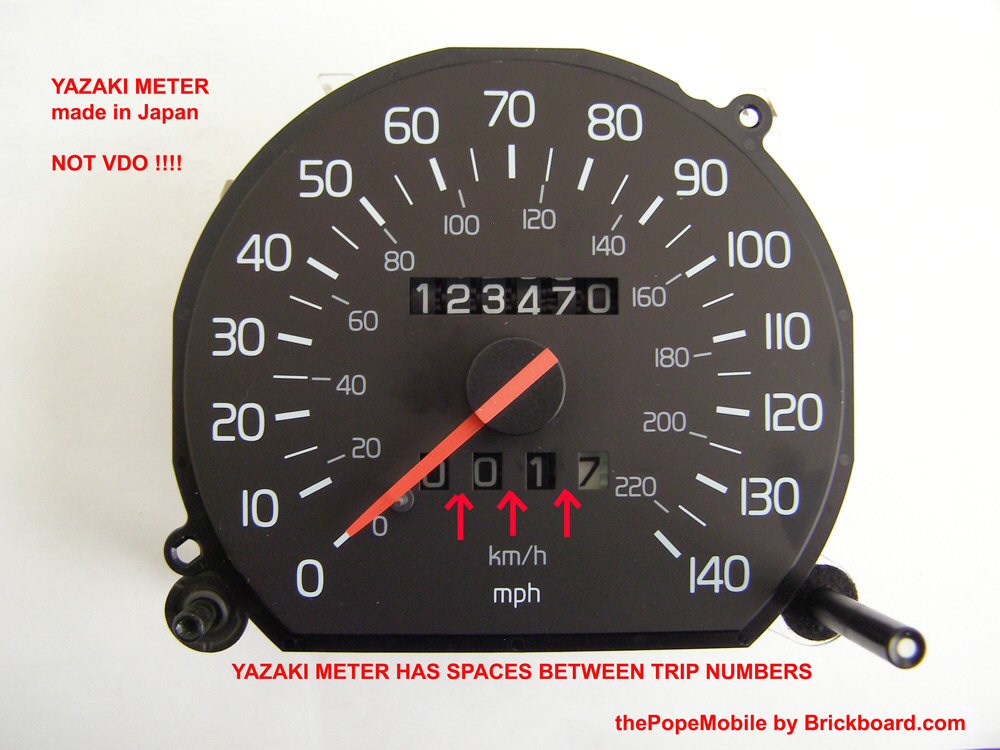
[Scott Cook] When I talked to the instrument/radio division of the very competent local Euro shop (Volvo, Mercedes-Benz, and BMW only), they said that the VDO speedos were repairable, but the Yazakis were much harder as noted below in the resoldering descriptions. He also said that partsand replacements were available for the VDOs but neither for the Yazakis. [Editor] Borton Volvo reports some Yazaki units still available from Volvo for around $450 each.
C. Fault location.
REAR SENDER TEST:
Faults are usually either in the gage itself or the rear sender.
A very effective and easy way to diagnose the rear sender is to disconnect the rear connector on the differential case and connect two long pieces of wires to the plug coming from the vehicle wiring, bring the “extension” wires inside the car, start the car, and start shorting the wires at a pace of 4-5 shorts per second. If the gage is OK you should start to read a speed over 15MPH. The faster you short, the higher the speed.
If you have a reading, then STOP HERE, and instead of tearing your dash apart, remove the rear sender unit, clean it using DeOxIt electronics cleaner (available at Radio Shack and good electronics stores) or eventually replace it (and while you are at it change your rear differential oil!). See the notes in the Instruments FAQ File on replacement of the rear sensor connectors, which become corroded. Volvo sells replacements.
ERRATIC READING:
If your speedometer has a reading when you start driving and then suddenly goes dead, or if it will indicate constant speeds, then it is probably the gage and this guide will help you. [Editor] In my instance, the odometer worked intermittently, only when the a/c was on. The instructions below solved the problem.
On rare occasions the responsible for erratic readings has been found in the grounding bar located in the driver foot compartment (worth to check before tearing the dash apart).
D. Dash disassembly and Removing the Cluster.
Depending on your car model, see the FAQ file for instructions on how to remove the trim and cluster.
PREVENT DAMAGE ON THE BENCH:
[Paul Ramdial] To prevent damage to the instrument faces, buy a styrofoam or foam rubber sheet of sufficient thickness (about one inch) to allow the speedo dial to rest on it with the reset shaft inserted into a hole in the sheet. Be VERY careful about not damaging the fragile zero position pin which breaks off in a heartbeat. [See below for replacement tips].
OPENING THE INSTRUMENT CLUSTER:
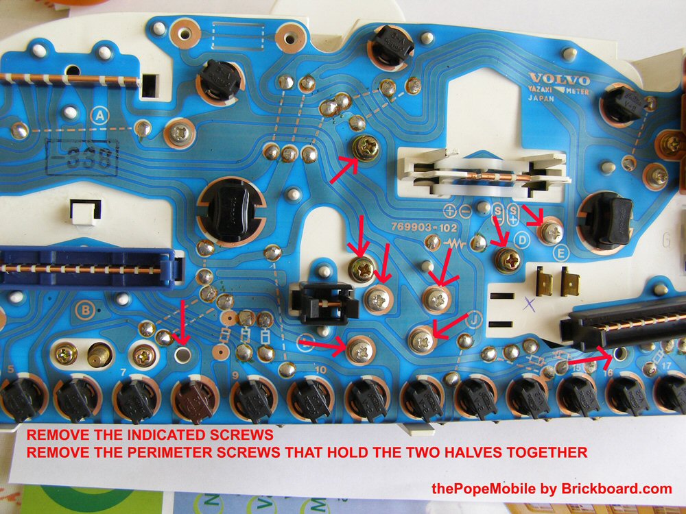
Remove the screws and then separate the two halves. First mark the perimeter screws and holes with one color permanent marker, then the cadmium plated silver screws below the speedometer connector. Mark the larger brass screws in another color. Place the screws in separate containers so you don't mix them up when reassembling. Your speedometer electrical ribbon connector may have a plastic clip holding it in place and serving as an indicator that the speedometer has been removed: snap the tab off by pulling.
REMOVING THE SPEEDOMETER UNIT:
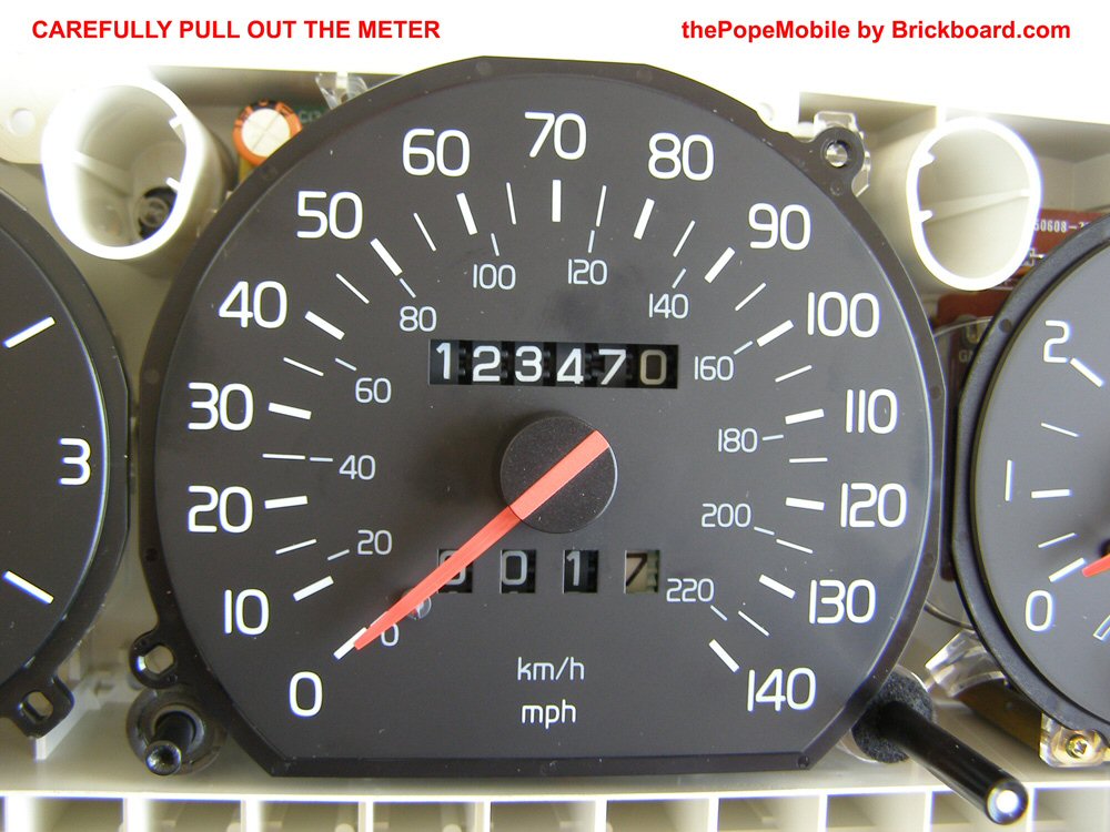
After removing the screws and separating the halves of the cluster, carefully pull the speedometer unit out. Keep your fingers away from the gauge face to avoid grease spots. Once separated, place the speedometer face down on your styrofoam or foam rubber sheet as noted above: don't even THINK about laying it face down on a hard benchtop.
E. Speedometer Surgery
MINOR CLEANING:
[Editor] Inspect the board and in particular the IC leads around the capacitors noted below. If only minor corrosion is present, clean it up as noted without disassembling the IC board from the unit: that sufficed in my case for a year. You will eventually have to replace the capacitors that are leaking which will require disassembly.
A multilayer PCB has a very small tube through the entire thickness of the board to which the components' lead is soldered insuring the component is making solid contact with the foil traces in layers of the board. This means that the entire hole is filled with solder, not just the visible surfaces. The solder needs to be removed without removing or damaging the tube or the foil around it. Clearing the hole of the remaining solder in order to install the new component is what can be a nightmare; removing the actual component in itself is relatively simple. For soldering tips, see numerous Web sites including EHow and YouTube as well as the Weller Guide to Better Soldering in the FAQ pdf file.
CAPACITOR REMOVAL: Use a good quality soldering gun, small tip, for electronic use. Use a vacuum desoldering pump to clean up the holes. You may need small needle nose pliers to help pull the component leads out of the holes. To remove the capacitors, preheat your soldering iron to roughly 450 degrees Celsius.
-
Make a diagram of the board with the existing capacitors, noting positive "+" and negative "-" leads so you can install the new units with correct polarity. These are marked on the sides of the capacitors. Sometimes the board is marked with a "+" or "-" or with a "half moon" shaded area for negative leads. If you can't see the board marks, note the orientation of the existing capacitors.
-
Choose your first target capacitor, and heat the POSITIVE lead up until the solder melts. With the iron still on the POSITIVE lead, push the capacitor toward the NEGATIVE lead until the POSITIVE lead is free of the board, and remove the iron from the board.
-
Now do the same to the NEGATIVE lead, and the capacitor will be free from the board, simply pitch it in the trash (I tend to toss 'em on the floor in my shop).
- [Editor] Mine were a little tough to remove, so I first heated the tips of the leads on the back of the board and pushed these into the board flush with the holes. Then I heated the leads as above and they came right out.
- Now to clean the holes out....... Reheat the hole on the back side of the board, if necessary, melt a little fresh solder into the hole to smooth it. Then using your 'solder sucker' on the front side of the hole, suck the solder from the hole. When you are done doing that, the hole should be nice, round, and able to see light through it if held up.
- If you weren't that lucky and the hole remains closed, here's what you need to do. DO NOT TRY THE 'SOLDER SUCKER' MORE THAN TWICE!!! If you do, you can damage your board!! You need to reheat the hole until the solder is melted, then insert the needle pick into the hole as far as it will fit without forcing it, going all the way through, immerging from the other side... Remove the iron and let the solder harden. Since the pick is stainless steel, the solder will not adhere to it. GENTLY spin and wiggle the pick around until it breaks loose, then remove it from the hole. Use your Exact-o knife and gently scrape the dry solder from the hole. And WALLA!! You will have a clean open hole, ready to place a NEW capacitor in!!
CAPACITOR INSTALLATION:
-
Use electronics rosin-core solder, heat your soldering iron to about 260 degrees C to start, and tin your tip. Some small tips do not conduct heat fast enough and may require a higher temperature. Too high and you will not wet the components correctly. See the Weller Better Soldering Guide.
-
Insert the new capacitor fully into the hole, NOTING THE POLARITY IS CORRECT!!!
-
Heat the lead of the capacitor and apply solder until you see it fill the hole. Don't put so much solder on that it shorts against adjacent traces or solder pads. It should become a shiny conical cap above the lead end on both sides of the board, just covering the pad. If it is gray or mottled, your tip is too hot.
-
Use your side cutters or dykes and trim the lead off. CAUTION: do not allow the cutters to cut into the board circuit traces.
-
Repeat for all the caps you're replacing
OPENING UP YOUR SPEEDOMETER. [Editor] There are two methods to open up the speedometer unit and separate the IC boards to repair the speedometer capacitors and board connectors. The first method is shown below as the Cable Method and requires very good soldering skills and close work. It has some risks, particularly in desoldering the small coil wires and not being able to reattach them. The second method is shown below as the Needle Method and is easier. You disassemble the unit by first removing the indicator needle. The risk is that might you break the needle or reinstall it incorrectly.
[Method 1: CABLE METHOD Requiring Desoldering the Cables: [Davide]
Make some notes as to wiring locations and colors so you can reassemble correctly (see photos of different model PCBs below):
- Desolder the flexible contact of the odometer from the board.
- Desolder the two wires of the service reset switch.
- Desolder the 4 pins of the speed indicator gage.
- Remove the screws of the indicator gage.
At this point, if the 4 pins have been correctly desolded you should be able to push the gage with your thumb and to remove the IC board. If the thumb pressure system does not work, keep heating up the pins with the soldering gun, one at a time, until you slide out the gage.
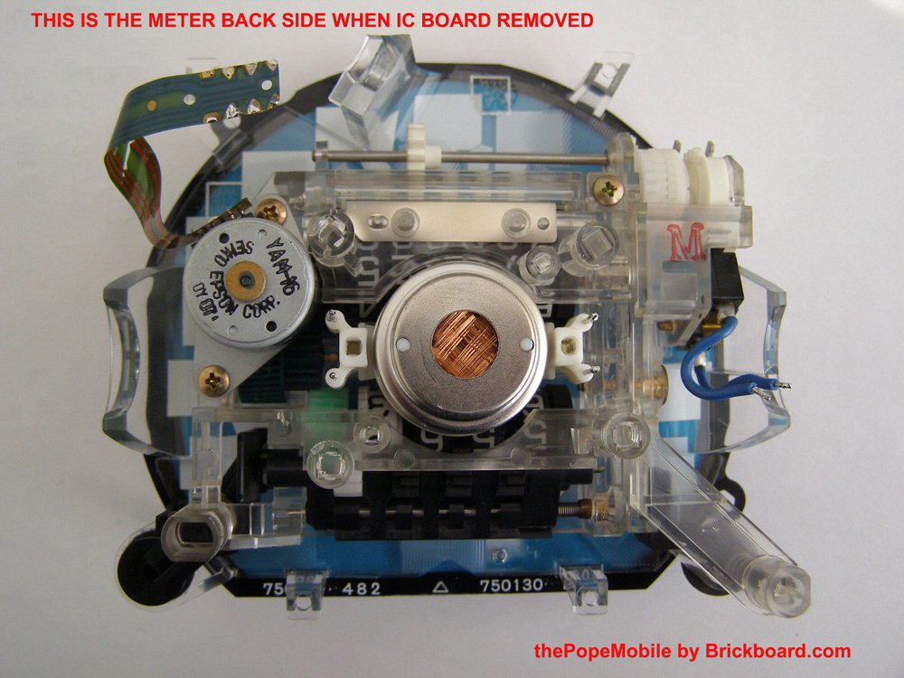
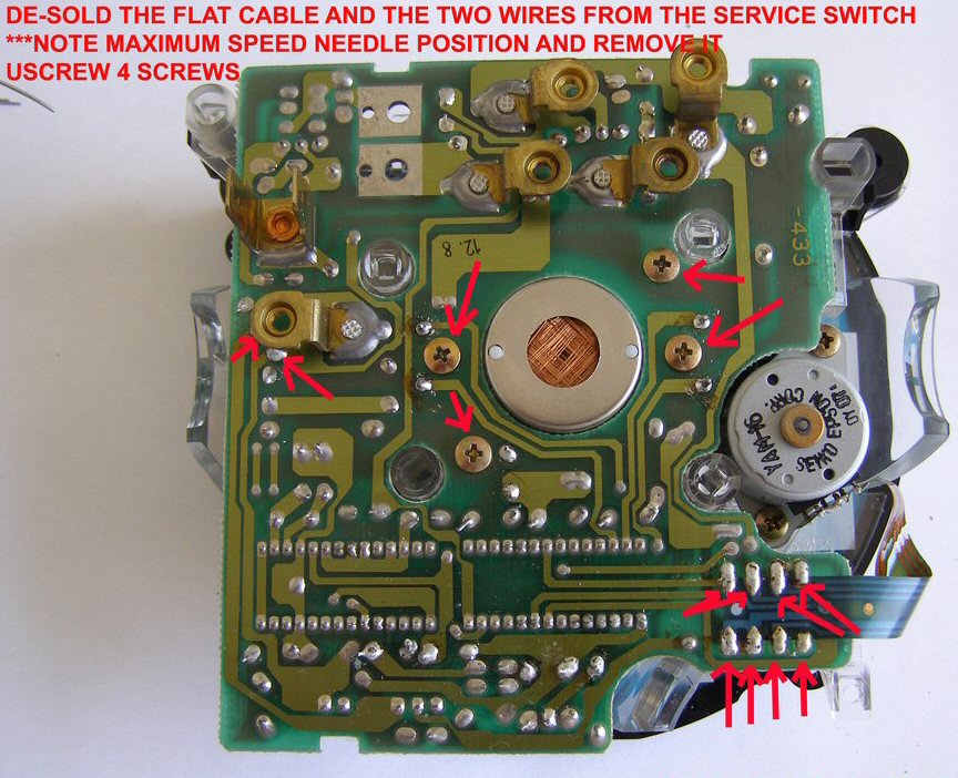 PCB from 91 940
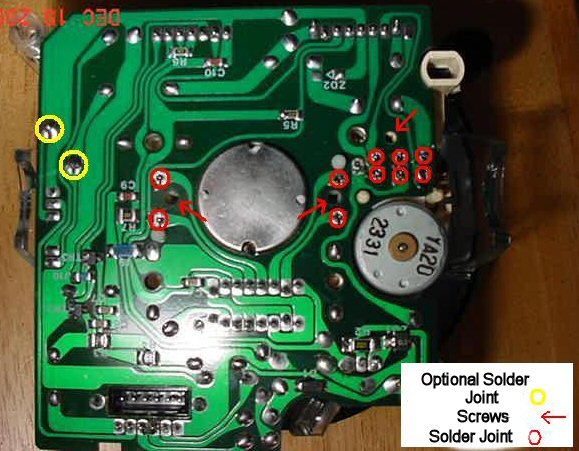 PCB from 93 940. The red circles are the joints that must be de-soldered, the yellow
circles are optional. Arrows are the two screws that need to be removed. Note that the 4 resolder joints next to the screws for the speedo pins are very difficult.
PCB from 93 940. The red circles are the joints that must be de-soldered, the yellow
circles are optional. Arrows are the two screws that need to be removed. Note that the 4 resolder joints next to the screws for the speedo pins are very difficult.
They tend to slide down in the white plastic speedo mount as you try to line them up in the circuit board holes. See the tips below.
Desoldering Tips: [Paul Ramdial] As I am somewhat proficient with soldering and such I felt more
comfortable working with the PCB off the unit. Removing the ribbon is
not really a big deal once you have the proper equipment such as a
suction manual desoldering tool. I do not recommend desoldering braid . Once most of the solder is removed the ribbon
still will not separate freely as any residual solder would still hold
the ribbon in place. To remove it, just reheat the soldering points one at a time and
lift with a tooth pick and before you know it the ribbon is off. See Soldering Tips above.
Reassembly. It is
hard to reinstall the ribbon incorrectly . Once aligned just one solder
point will keep the ribbon true then you can resolder. The trick with
the four pins from the speedo movement is, once most of the solder
is removed, to lift the pcb gently while heating the pins. Do one at a time
and once the the board is separated widen the four holes a bit so
reinstallation is easy. If the holes are not wide
and clean then when you try to reinstall the pcb you will end up
pushing the pins down. If you do, use small pliers and gently lift
them up a bit. The pins should just protrude out so you can have a good
soldering point. [Ryan Ridgely] The problem with de-soldering the 4-pins to the speedo's magnetic coil windings (marked sin/cos is the heat on those pins which conducts to the other ends and you loosen the coil windings off of those pins (which aren't very well attached). This is apparently what happened to me, as I discovered the windings hanging loose when I did a post-mortem on what was an unsuccessful repair. At that point, the speedo guts are toast, because it's really just impossible to reattach them. See the alternative techique below.
Method 2: NEEDLE METHOD Requiring Removal of the Indicator Needle: [Randy Starkie] Davide's disassembly above calls for no less than 11 unsoldering points (either 5 or 8 on a ribbon with multiple joints, 2 blue wires on the switch, and 4 pins from the gauge unit) to disassemble the speedometer. While I am comfortable unsoldering/resoldering joints on a board I find working with ribbon fraught with chances of error. We have had reports of owners unable to resolder the small ribbon or coil wires. [Editor] See the Tips and Techniques section G below for specific tips on how to use this simpler method.] Caution: Be very careful of the pegs on any of the gauges. They are very fragile and easily broken off.
Desolder the Blue Service Light Wires at the Board. I was able to reduce the number of unsolderings to just two. If your car has a service light to remind you to change the oil and
requires resetting to get it to go out then you should have the blue wires
(see photo) connecting the microswitch to the board that need to be desoldered from the board at the points circled below. 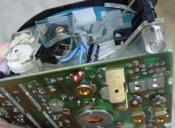 After disconnecting those from the board the remaining disassembly was only to remove the indicator needle and some screws.
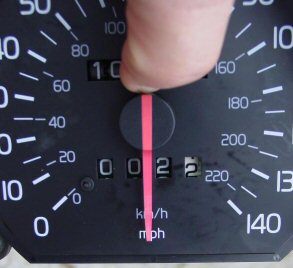
Remove the Indicator Needle. Begin by removing the needle. Gently rotate the needle by hand to its maximum stopping point and note (or mark) this point which is more or less the “m” in the mph at the bottom of the face. The needle is then removed by very gently turning it and lifting straight up after you carefully lift it over the zero peg. It is more about lifting and wiggling than it is about twisting. It is pressed on and the method of getting it off can only be described as "pulling". The thin “zero pegs” on all these gauges are very fragile and easy to break off so be careful … Yes, scary stuff, but would you rather unsolder and resolder the remaining 9 solder points as noted above? Pick your poison. The photo below shows where the needle stops if you gently advance it to what would be the maximum speed (around 160mph) or the end of its travel.
[Alternative Removal Method: Randy Starkie] In my opinion that makes the needle difficult to install as you must get it turned to that position before replacing the needle. To remove the needle indicator, I like to carefully flex the needle end up over the zero peg being very careful not to break the peg and let it find its unrestricted home position. Flex it just enough to clear the peg and then gently lower it and let it go. It will settle at what I refer to as the "home" position. I think you will find that it is very close to being the "m" in the mph stamped at the bottom of the speedometer face. Make note of where that position is. When reinstalling it I simply replace the needle in that position and then carefully flex the needle up over the peg before pressing it home. Remember: the needle has to go back on with the same orientation on its attachment point or the speedometer will not be accurate. Once you have located the home position you can begin to pull the needle off : use your fingers around the outside of the circumference of the needle base and pull while applying a slight wiggle side to side. While applying the wiggle increase the pulling tension and it will pop off. When replacing the needle push it onto its pivot point slightly while in the home position. Double check the position and carefully flex the end over the zero peg before pushing the needle down to secure it. By waiting to push it down you make it easier to lift the end over the zero peg. Of course it has to be on enough that it does not slip while lifting it over the zero peg. See Tips below.
Separate the Board from the Unit. Continue removing the board by removing the four small Phillips head screws near the center of the opposite side of the board. Only two of them really need to be removed but it is hard to tell which ones they are until you have taken the board loose. At this point the board will come loose but still be attached by the ribbon cable on the motor (see photo). [John Gibson] Once the boards are separated I strongly recomend pushing the meter needle gently back on its shaft in order to protect the delicate hair spring.
Disconnect the Odometer Motor and Ribbon Cable. Do not de-solder the cable. With the 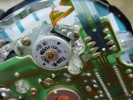 board loose you have access to both screws that hold the odometer motor in place. Remove those two screws and the odometer motor lifts free and stays with the board, preventing overstress on the ribbon cable connector. You now have access to the both sides of the circuit board and the capacitors that are referenced in Davide’s tutorial below. Lay the two halves of the assembly on your foam sheet.
You can further disassemble the remaining portion by using a knife to separate the face from the clear plastic structure. Gentle prying of the face all around will pull the adhesive points loose and the face will come off. The adhesive remains tacky and simply press the face on for reassembly. The removal of the face will reveal two small Phillips head screws that when removed will leave the mechanical portion of the odometers free of attachments.
Reassembly [Randy Starkie's Method]: Assembly is straightforward based on the disassembly above. Care needs to be taken to see that the pin is rotated all the way clockwise to its stop before pushing the needle on at the stop point you found before taking it off.
Having separated the PCB from the unit, you can now proceed to the actual repair:
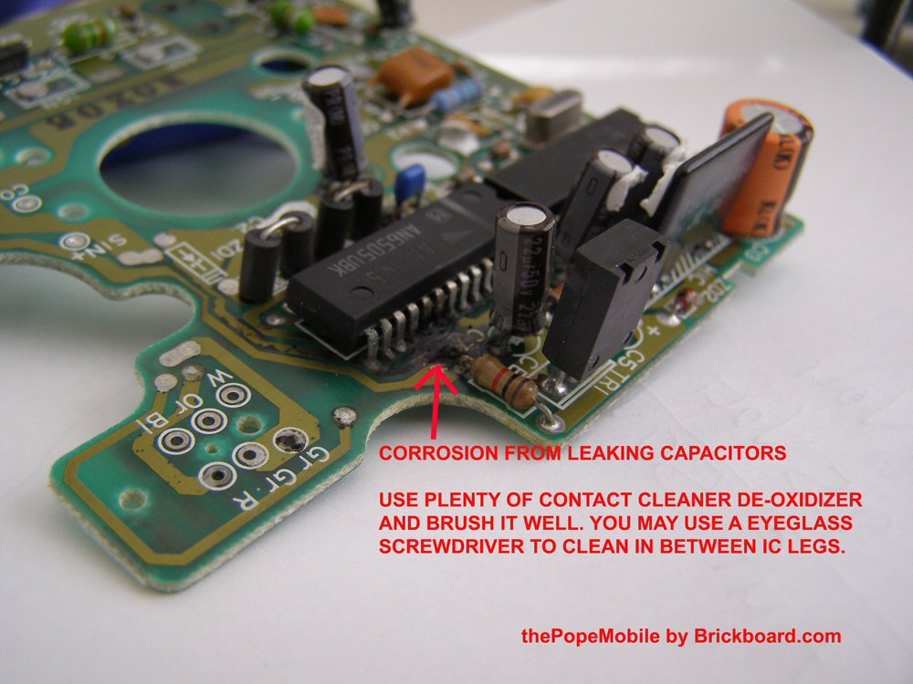
LOCATING THE CAPACITORS AT FAULT:
Now you should be able to see four capacitors, the source of your speedometer fault:
C7 – C12 – C6 – C16 and their good cousin C15.
The first four electrolytic capacitors have leaked their acid content on the board causing corrosion and shorting nearby components. The C15 is their good cousin since it usually doesn't leak. [Editor] Replace this as well, given the difficulty of the job.
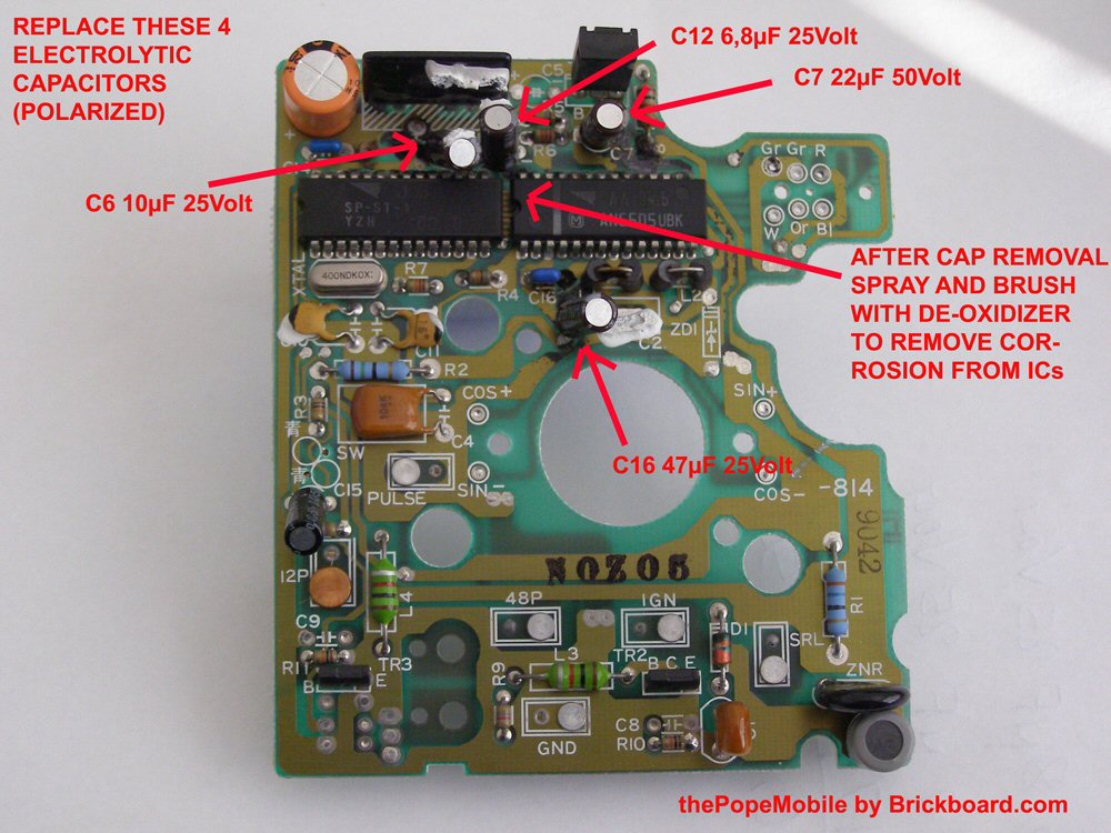
REPLACING THE CAPACITORS:
Sourcing New Capacitors. [Davide/Michael Melkonian/Matt Lietzke] Buy new electrolytic aluminum capacitors from Digikey, Mouser or a local electronics store. These are small  Coke-can shaped capacitors with dimensions around 2cm long by 1cm in diameter. Buy Japanese, not Chinese, parts for quality. Here are the values you need:
- C7: 22µF 50Volt (Mouser p/n:USR1H220MDD)
- C12: 6.8µF 25Volt (Mouser p/n:UVR1H6R8MDD)
- C6: 10µF 25Volt (Mouser p/n:UVR1E100MDD)
- C16: 47µF 25Volt (Mouser p/n:UVR1E470MDD)
- C15: 0.47µF 25Volt, bipolar (Mouser p/n:UEP1HR47MDD)
- Corner Large Capacitor: 220µ F 50Volt: see photo below for this capacitor (shown as orange in top left)
You can use higher voltage rated capacitors, just do not go below the indicated voltage. Higher voltage means often bulkier sizes, so be careful not to buy something too large. But make sure the capacitance is the same as the original. The specifications in the Digikey list should be "General Purpose" except for the one bipolar capacitor; "Radial Leads" with spacing up to 7mm (I believe the originals were radial but you might be able to get by with axial if necessary); "Through Hole"; and "Tolerance +/- 20% or less". The rest of the specifications are not important. When using Digikey, search for the parts by filtering sequentially "capacitor" then "aluminum" then the capacitance value then the other values.
Repair Procedures:
- Desolder capacitators C7 – C12 – C6 – C16 and since we are at it also C15. See Soldering Tips above.
NOTE THEIR POLARITY!!! WRITE IT DOWN SINCE THEY ARE POLARIZED! (except C15 which may be installed either way). The circuit board should show a small "+" and "-" where the leads are soldered but these may be obscured by solder or corrosion. If the board indicators are obscured, note the orientation of the existing capacitors BEFORE you remove them: the white stripes are on the negative sides. NOTE AS WELL whether they are soldered on both sides of the board or just one so that you can replicate the original soldering and not err on a multilayer board. Polarity of the new electrolytic capacitors will be shown on the sides: the cans may have a + or - marking, may have a white stripe with a "0" or "-" on the negative side, and the negative lead is shorter than the positive lead.
- Spray the board near the old capacitors with electronic contact cleaner/deoxidizer such as DeOxIt and use a tooth brush to clean the mess the faulty capacitors have created. [Editor] In my case, only a small amount of corrosion was present which was removed using DeOxIt on a toothpick between the IC leads and on a foam electronics cleaner Q-tip from Radio Shack.
- Re-flow all the nearby components. Pay attention to the two ICs; their pins are very close each other. Do not short them out. See Soldering Tips above.
- Reinstall the new electrolytic capacitors paying close attention to +/- polarity (except C15):
- C7: 22µF 50Volt
- C12: 6.8µF 25Volt
- C6: 10µF 25Volt
- C16: 47µF 25Volt
- C15: 0.47µF 25Volt, bipolar
E. Reinstalling the PCB and Reassembling the Speedometer
It's exactly the reversal of everything. Just make a test drive after you reconnected the wires, before reinstalling all the plastic moldings.
Alternate Needle Removal Method 2: Reassembly is straightforward based on the disassembly above. Care needs to be taken to see that the pin is rotated all the way clockwise to its stop before pushing the needle on at the stop point you found before taking it off. See Tips below.
F. Potential Continuing Problems
Some respondents have reported that after this repair, their speedometers do not read greater than 45 mph. This may be an artifact of IC damage due to shorts across the corroded pins on the board. In one case in which the needle pegged at 40mph regardless of speed, it was caused by a loose ground wire. In other cases, it may be related to bad solder joints on the flexible PC board on the back of the panel. Reflowing these with new solder solved the problem in at least one instance.
G. Collected Tips and Techniques
Easier Needle Disassembly Method: [Rob Miller] I highly recommend taking the speedo apart by turning the dial counter clockwise and popping it off as noted in these tips and in Randy Starkie's method above.
There is a white security clip on the 4 pin connector behind the speedo. It breaks so don't worry when removing the speedometer. Try not to touch the gauge surface: it doesn't like greasy hands.
- Remove the dial needle by lifting it up and over the stop pin and turn
and pull counter-clockwise. When you put it back on, set it so it full stops clockwise
at over the k in km/hr bottom mark. Detailed technique:
- Rotate the needle to full stop. You will see the needle stops about over the km on the km/hr stamp. Rememeber this to reset the needle.
- Release the needle so it goes back to 0 and rests on the stop pin.
- This is the part that is scary: lift up the end of the needle over the stop pin so that it clears the pin while rotating the needle counter CW.
- Keep going Counter CW until the needle finds its internal stop. Gently keep going to release the needle base grip on the speedo center mast pin.
- Once it releases, gently pull the needle straight off while turning it counterCW.
- You many need to go over the stop pin again. Just lift the needle over it again.
- The stop pin is fragile, so be careful.
- See also Randy's notes above.
- To reinstall the needle, lightly place the needle on the speedo mast pin (enough for a gentle fit). Rotate needle clockwise until the needle stops over the km mark (remember) - and then push the needle base down on the center mast pin to keep it in place during final use.
- The service light switch wires have to be unsoldered to separate the dial from board. [Optional:] If you don't care about the service light ever working, when the switch is in the down position (light off), check if this is an open or closed circuit on the circuit loop - and then solder a little jumper wire across the solder points if it is a closed normal condition. You can remove the switch off the clear plastic mount by drilling a little hole into the clear plastic just in front of the switch mount screw - and then using a little jewel screwdriver, back it out thru the drilled hole. The switch comes off with a little wiggle and pry up off the additional clear plastic pin into the switch. Getting it back on this way is tricky.
- Keep the Ribbon Connector Intact: Remove the 2 little screws near the center on the odometer motor with the worm gear. Take a small zip tie and tie the worm gear to the narrow projection of the circuit board over the connector ribbon. This way it doesn't flop around and possibly break the ribbon. Then remove just two of the remaining 4 screws next to the center: not the ones centered between the speedo pins which remain in place.
- Clean that board well with electrical contact cleaner. Get a toilet paper roll and cut a little strip to fit under the two IC's. Soak it with cleaner and clean under the IC. Clean between the IC legs. Toothpicks or hobby brushes (the plastic kind with a tiny pad of foam for paint) also work.
- Check all circuit paths for continuity with a DMM. Note the circuit paths are different on each side. It really helps to hold the board up to a strong light to see the paths. Check them for corrision damage. I had to jump one with a small wire from the 7th leg of the IC to a capacitor leg because the path was burned thru from capacitor acid. A good DMM meter can check the capacitor reading. GO THRU EACH ONE AND TEST THEM! A LEAK IS NOT THE ONLY SIGN. Or just replace the lot: I did all of mine.
- Make a picture of the existing cap's so you can reinstall them correctly. Getting the capacitors off is done by twisting the cap side to side as you heat each leg pin from underneath to break the solder with the heat. They will slowly walk off the board. Reinstall in reverse. Get the polarity correct: the striped side of a cap is negative as is the shorter lead. Cut the new cap's leads so they are not so long. Also, the tach needed a new 6.8 micro F capacitor. Fixed it while the cluster was apart.
- Reinstall the Needle at the k in km/hr at full clockwise spin. First review Randy's notes above.
Very easy. Now my speedo and tach work!
Needle Stop Pin Replacement. [Editor] If you are as clumsy as I am, you broke a needle stop pin off. If this happens, obtain a thin piece of brass wire and a matching very small drill bit from a hobby store. Cut the broken plastic pin off flush with the base using cutter pliers, then drill a hole at the base of the old pin. Cut a piece of brass wire long enough to insert into the hole and extend above the plane of the rotating needle. Position the indicator needle correctly then superglue the wire into the hole. Paint it flat black and you are back in business.