Heating and Air Conditioning
Heater, Vents, Vacuum Controls, and Blower Motor:
Heater Vacuum Controls, Source, Leaks
Vents Blowing Black Foam Specks
Interior Water Leaks: Loose Water Shields/Clogged Ventilation/AC Drains
Air Conditioning:
Air Conditioning System Maintenance
Poor A/C Performance: Diagnosis
A/C Compressor Cycling or Not Engaging
A/C: R134 change from R12 in Volvo cars
Variable Orifice Valve Addition
R134 versus Refrigerant Alternatives
A/C: Adding High Pressure Cutoff Switch to pre-1992 Cars
Rebuild or Replace A/C Compressor?
Climate Control Units:
Access to Climate Control Unit
MCC Climate Control A/C Malfunctioning
ACC Heater Control Not Working
ACC Climate Control Instability
ACC Temperature Sensor Not Operating
ECC Climate Unit Not Operating
ECC Climate Unit Diagnostic Codes
Vacuum Servos:
Panel Vent Stops Working Upon Acceleration
Replacing Vacuum Servos in ACC-Equipped 700/900 Cars
Upgrades:
Diagrams
Heater, Vents, Vacuum Controls, and Blower Motor:
Heater Vacuum Controls, Source, Leaks.
Leaking Sound from Heater Controls. [John Sargent] One of my 740s made a hissing sound from under the dash in the area of the heater temperature control lever. The manual heater control assembly supplies vacuum to the under hood heater valve to shut off coolant flow to the heater core in the cold position of the control lever. The vacuum connection had come off the heater valve, and the free flow of air caused the hissing sound at the heater control. Connecting the vacuum hose to the heater valve cured the hissing sound, and shut off the flow of coolant through the heater core. See also the notes below under Vacuum Check Valves. See instructions for help on removing the vacuum hoses at the back. This rear connection has been known to leak.
Leaking Sound from Under Dash.
That vacuum leak is almost certainly your floor/defrost diaphragm. It is on the left side of case just above the accelerator pedal. This diaphragm unit is double acting, i.e. it has vacuum to pull it both ways, blue hose for defrost and yellow for floor. There is a boot that seals the side that yellow hose applies vacuum to and when this boot goes bad it leaks when you use a/c or floor settings. It is a HARD job to replace this diaphragm unit. It requires removing a lot of under dash parts and ducts and then standing on your head to reach two extremely hard to get at nuts. I would try blocking the yellow hose with an old style fuse (the glass w/ metal end cap kind) and see if you notice any real compromise in operation, you won't ever get the full flow to floor and you'll always have some air out of defrost any time that you aren't on a/c. 
Vacuum Check Valve Failures.
[Inquiry] I have a 1990 760T and the H/AC is losing vacuum during low vacuum and during boost from the turbo. There is a tee above the intake that has two black & white fitting that connect to two smaller hoses that go to the fire wall. I suspect these supply vaccum to the H/AC but does anyone know if these are actual check valves to prevent vacuum or boost from entering the system?
[Response: RL] There are numerous sources of potential vacuum leak (including some of the vacuum motors (bellows) on the actual heat AC system) but those two valves are a common problem. They are check valves to prevent loss of vacuum and if you bench-test them individually, you may find that they perform well under a fair amount of vacuum but that as soon as you try minimal vacuum, the valves will give up. You may try cleaning them out in WD40 or some rubber-softening substance but failing that, your best bet is probably an OEM replacement. [Dave Stevens] If you have a turbo, that hiss is from the pneumatic vacuum reservoir for the dash heater & A/C air distribution system. Your turbo uses a vacuum pump rather than manifold vacuum to evacuate this container which is why your symptoms are noticeable under acceleration rather than deceleration as you'd expect with an NA engine. Normally there is a slight hiss whenever you change the heater control positions. In your case it seems there is a more noticeable sound and it's hissing under other conditions. Although I haven't had this particular problem, I understand it's often caused by a leak inside the heater control unit itself. You can replace it or just live with it. It could be a leaking diaphragm in one of the air diverter servo motors, but that normally just causes loss of functionality rather than hissing. Could also be a loose hose at one of the servos, but these are fastened pretty good. I doubt you'd find a split hose anywhere.
[Tip: Chris de Courcy-Bower ] If the air conditioning misbehaves and hisses when accelerating, check the two one-way valves that connect the climate control system vacuum pipes to the inlet manifold. If they let ANY air through in the from manifold direction when you gently blow into them then replace them. (The good news is they are cheap)
[John Sargent] The two black and white check valves are shown in the picture to the right. The car is a 1988 760T but most are similar. One hose is for the ACC, and the other is for the temperature sniffer in the dome light (if so equipped). I found that the hoses leaked at the check valves and using the small worm drive hose clamps took care of the leaks. Prior to that the panel vents would snap shut as soon as you depressed the gas pedal
Application of Vacuum to Water Control Valve.
[Inquiry] My heater won't shut off. When is the hot water control valve in the engine compartment shut off?
[Response] Vacuum to close the water valve is only applied in max AC mode or when the MCC temperature selector is fully cold. This varies according to the type of control system in the car (MCC, ACC, ECC) and the Volvo OEM service manual should be consulted for details of vacuum signals.
[Inquiry:] The heater in my 745TD still thinks it's summer... The engine itself heats up in a normal period of time, coolant temperature is at a normal level. The coolant system builds up pressure in the expansion tank. This morning I put a piece of cardboard in front of the radiator. I still got cold feet, so the thermostat is OK, right? The hoses that go towards the heating element are fairly warm. The air from the top dash vents is not very warm and even on position 4 the flow is rather weak. The middle vents are warmer and the flowrate is good. The flowrate below is nearly neglible and the temperature is just above 0 C.
[Response: Dennis Hamblet] Several suggestions:
- Your thermostat needs replacement and your dash gauge is not reading correctly. Cheap and easy to put in a new thermostat to confirm.
- Your heater core has a deposit of sediment or minerals restricting the flow of warm coolant in which case the system may benefit from a backflush.
- The heater water valve has a blockage restricting flow and may be in need of replacement;
- You have a vacuum leak which causes the heat vent control to work improperly;
- Your firewall-side heater water valve was installed backwards; The arrow on the valve points to towards the firewall inlet, not back towards the engine.
- Control cables from the heater control unit to air mixing doors are maladjusted or broken. In heater-only cars (no AC unit), the water valve (which is inside the cabin, above the left footwell) is controlled by a cable from the air mixing door.
- [Pete Fluitman] Check the heater hoses, I have seen several 700's where they are swapped over and it results in ZERO heat. See the section on Water Valve Replacement for correct installation instructions.
Heater Won't Completely Shut Off Hot Air.
[Tip from John Sargent] 700 series, with manual temperature selection, have a reputation for not being able to completely shut off all of the warm air when the manual temperature selector is fully off. The problem is the flapper door in the heater is not fully closed. There is an adjustment for this in the cable, just behind the heater control. If you remove the glove compartment, you can see the heater controls. The cable on the bottom controls the flapper valve for heat. The adjustable part of the cable is at the heater control. If you see a larger part of the cable, about 3/8 inch and about 2 inches long, that is it. Turn that larger part of the cable until you can feel the temperature control knob moving off of its left hand stop. You are done!
[Inquiry:] I guess that the heater core in my 86 740 Turbo
wagon is leaking cause I have antifreeze on the front floor. Is this as nasty a job as it looks?
[Response:] Try to find out where the coolant is coming from. Usually if the core goes bad you get a coolant mist on the windshield with the defrosters on and you can get some coolant drainage from the A/C condensate line or onto the carpets. As a temporary fix, you can add a stop leak additive to the cooling system. But plan on a new core soon.
[Editor] Note that air conditioned cars do not have hoses or a water valve inside the passenger compartment. Cars with heater only have a water valve on the left side of the console against the firewall inside the passenger compartment and this can leak, appearing as though the core is leaking.
Heater Core Replacement: See the separate FAQ file which explains the replacement procedure for the Manual Climate Control-equipped car. ACC and ECC are similar. [Tips from Bob] I have done 2 heater cores on 700 series cars. It is very labor intensive. You have to take apart the lower half of the dash and partially disassemble the heater case. The heater core is on the left lower side of the case. You need to remove radio, fusebox, left side center console panel, bracket that holds fusebox,bottom left side air distributon box. When you can finally see the heater core, it looks like a hand grenade went off in your car. If you are not familiar with the procedure, plan on a weekend. You MUST have a good shop manual. I strongly recommend getting the Volvo OEM climate unit manual (see Volvo Technical Literature.)
Repeated Heater Core Failures:
If your car suffers from heater core failures, consider coolant breakdown due to combustion gases from headgasket leaks as one possible source.
Leaking Hose Connection Masking as Core Leak.
[Jim Parker] When I replaced the heater hoses, I gouged the surface of the brass core nipples with a razor knife or screw driver when cutting and prying off old hoses. The new hose was pushed up tight against the fire wall that has a opening around the nipple filled with a porous rubber sponge, where it leaked. I pressure tested my core before pulling it and it held pressure! So I sanded/cleaned the nipples and reinstalled hoses, which sealed the second time and my leak/problem was cured.
Water Valve Replacement. The heater water valve controls the flow of coolant to the heater core. If this plastic-bodied unit cracks, you will instantly lose a majority of your coolant. The engine-side valves installed in air conditioned cars are exposed to much more heat and have a shorter lifespan than the passenger-side valves in heater-only cars. The engine-side units last about eight years and should then be discarded. When you replace this, consider new heater hoses as well.
Part Quality. The rather pricey Volvo OEM valve 9447896 is top quality and lasts a long time. Quality goes down from there all the way to the cheap MTC brand valve for which several anecdotal reports on Brickboard note "avoid" since the valve failed within a year or so of installation and cooked the head gaskets. For a decent alternative, try the FourSeasons domestic water valve, part number 74612, widely available in parts stores for about $12. [John Martin ] Drop-in replacement for the OEM metal-and-plastic heater control valves used in the 740 and 940 is available from Ford dealers: Motorcraft part number YG-136. List price is $31.68, local dealer sold it to me for $18.80. Side-by-side, the valves are clearly the exact same thing. Local Volvo dealer wanted over $80, Tasca wants $64. Quite a mark-up from the red box to the blue box!! Some googling shows it's also available as D4AZ-18495-A for Fords, and under other numbers for some GM applications too. You will need to source a vacuum tube adapter as the nipple on the Motorcraft valve may be smaller than on the OE valve. Try a big box auto supply store.
For Air Conditioned Cars: The heater water valve is installed in the engine compartment, right near the top of the transmission fill tube and under the intake manifold near the firewall. It's hard to see it and the area is crowded: best to feel down the bottom heater hose until you find it. Be careful around the throttle and kickdown cables so you do not crack the end fittings. To replace:
- Disconnect battery ground. Pinch off both heater hoses in the engine compartment
- Remove the vacuum line attached to the valve
- Remove the valve. Clamp screws are 7 mm and you will need an extension and universal joint to access them.
- Install the new valve and tighten the clamps. [RMagoo] The valve goes between the heater hose connected to the short pipe coming out the cylinder head and the heater hose entering the bottom tube of the firewall connector . The arrow on the valve points toward the firewall. The top heater hose goes to the red pipe behind the head leading to the water pump.
- Install the vacuum line
For Heater-Only Cars: The heater water valve is installed in the left side footwell, up near the left edge of the center console behind the kickpanel. It is mounted to a plate on the firewall. It is round with a hose entering it from the heater core.
To remove:
- Disconnect battery ground and remove left side dash under panel and air hose
- Remove the accelerator pedal and the the ignition control box and, if you have it, the cruise control connector, all for better access.
- Clamp off lower hose from valve to heater core
- Clamp off lower hose in engine compartment then disconnect
- Place cloth on carpet to soak up spilled coolant
- Remove lower hose inside car connected to valve
- Remove control housing from water valve
- Remove plastic valve by rotating clockwise. Unhook cable
To Install:
- Reconnect cable to water valve
- Install valve by placing it on the mount and turning counterclockwise
- Mount and adjust the control housing
- Reconnect hoses under dash and in engine compartment
- Remove hose clamps
Make sure that the heater hoses are held by the plastic clips that keep them away from the block, the EGR system, and other areas they can wear and leak.
Vents Blowing Black Foam Specks.
[Inquiry] I have black foam blowing out my vents. What do I need to do to fix this?
[Response: David] This comes from deteriorating foam sheets on air doors within the system. I popped all the air direction vents out with a small flat tip screwdriver. There are only two small nipples (one on each side) holding the vents in place. A little leverage and they come out easily. (BE CAREFUL!!! THE SMALL CURVED WASHERS THAT PROVIDE THE TENSION TO HOLD THE VENTS IN POSITION AREN'T ATTACHED TO ANYTHING!!!). I figured I could snake a small piece of garden hose taped to my shop vac and suck the stuff out. I cranked the A/C on high recirc and all the stuff just blew out. Didn't even get a chance to test the garden hose vac! Left the vents out for a couple of more weeks just to make sure there were no late arrivals. Armor All'd the vents and put them back in. No problem since.
[Response: Wong] I closed all the vents except one. Put the blower motor on the highest setting. Maybe if you turn the heat on it would help even more. Then stick a vacuum cleaner up to the vent and suck that crap out. Should take a few seconds. Use a little pick to help get some of the foam thru the vent slots. Move around and do the other vents one at a time.
Bearings Squeek. The usual failure mode is squeeking bearings due to age and wear.
Blower Motor Only Runs High. If the motor runs on only one speed, the failure mode is usually the resistance pack mounted in the air plenum. Sometimes this occurs in conjunction with a motor failure when an overcurrent in the motor causes the resistors to also fail.
General: Resistor Pack Failure
[Inquiry] Several days ago my blower/fan motor stopped working. It works on the highest setting which is number 5 but does not work on the lower settings. Local dealership
diagnosed a failed resistor that they determined was faulty in the motor.
[Response: Warren Bain] Probably a failed resistor pack. Remove the lower panel under the glove box, remove the glove box. There are two small covers on either side of the box with screws under them. The resistor pack is attached to the plenum with several wires close to the fan motor. Replace it. My car is 14 years old and has the original resistors. Make sure the blower motor works OK.
Specific to 1992+ 740:
[Inquiry] Fan switch only works on 5, no 1,2,3,4,? Is it the switch or is there a resistor pack or can it be the motor?
[Response: Abe Crombie] There are two things that come to mind dependent on how a 92 is wired. There may be a blower relay on the case behind glove box. It passes all the current from resistor to blower but on high the relay is energized and its contact switches over and feeds direct 12 v to blower saving the switch from having to carry the high amperage. If the contacts on the lower speed side are burnt this failure would occur. The other is the resistor itself. I believe a 92 has this feature but it might not have occured until 93, anyway, the resistor may have a temp fuse integrated into it that will go open if the blower resistor has debris around it or if the blower motor drags. Either of these two will make the resistor get hot enough to trip the temp fuse. If the resistor has the temp fuse it will be a green ceramic covered resistor and the temp fuse will be adjacent to ceramic core. It is a silver 3/16" cylinder with tapered ends , one of which is white. In either case i can tell you w/o too much doubt that you will have to go behind glove box as the relay is there and the resistor is stuck into the blower case in that area also.
Blower Motor Fails: Melted Heater Blower Fuse. See the FAQ section Melted Heater Blower Fuse
Heater Blower Motor Replacement.
Repair or Replace? If your motor is squeeking, you might be able to oil the bearings but most 740/940 motors have sealed and inaccessible bearings. Plan on a replacement motor.
[Tip from John McIntosh] It is quite easy to dismantle the motor by bending the tabs holding it together. Mine had been squealing and making sundry horrible noises. The rotor was encrusted with iron filings and the bearings were dry. I lubed the bearings with 3 in 1 soaking the felts, blew off the iron filings. Mounted the rotor in my drill chuck and filed the armature with a smooth flat file, finally polishing with glass paper (not emery which I am told is conductive). The hardest part of re-assembly is ensuring the brushes are held back whilst the armature is put in place. This was done using pieces of wire. Dont forget the cooling pipe when re-installing. My fan motor now runs silently and well.
- Pre-90 740 Cars: Earlier blower motors used generic units from GM. GM mid-80's blower motors for AC-equipped Chevy Citations are exact replacements. Another exact replacement is a Siemens-made replacement blower for a 1984 Chev Citation with the single power connection for use with air conditioning (Siemens part number is PM-105). Also: look for an '81 Olds Delta 88 w/ air conditioning blower motor.
- Pre-90 760 Cars: The replacement for the 760 series fan motor is a standard GM fan motor; at NAPA the part number is 455-1076. I was shopping for a fan motor for a '87 760. The clerk responded, $57.94 and we'll have to order it. Then, I said ok, Try a '83 Chevy Impala with AC. In-stock and $17.99 with lifetime warranty. In all cases, you will have to reuse the blower cage.
- Post 1990 740/940 Cars: A Factory Air #35339 that lists for $49.88 on the PartsAmerica website will fit with a different wiring pigtail made using an adaptor pigtail from a bit of heavy automotive wire and some female and male crimp on spade connectors. This will allow you to connect the original harness plug to the motor without hacking anything. Make sure the polarity is correct on installation so it does not run backwards. This is the same blower as used in any '91-'96 rear wheel drive full size General Motors car. Note that post-1990 cars use a different plastic mounting plate.
- The reason the original fan failed became quite apparent in today's rain. Water showed up around the new fan. Apparently the 740 has a tendency to leak on the passenger's side with the water ending up in the plastic basin that the fan sets in. [Note: See Volvo TSB for a fix for this problem.] [Second Comment:] After posting an e-mail question regarding heater blower motors on the Swedishbricks mailing list, I received a response from Bill Cheb that he rebuilds heater blower motors and adds ball bearings which should add an extra several hundred thousand miles to their endurance. Bill was easily accessible via e-mail at bill.cheb@ualberta.ca. He promptly responded with information on how to order. His delivery was prompt and included detailed instructions on how to install the new motor. The total cost including delivery was $125.00.
- 960/90 Series Cars: I found what was supposed to be a replacement at Advance Auto Parts for $29. It was an exact fit mechanically but had the wrong electrical connector. I returned the motor and ordered one from FCPGroton for $60, which was the same motor with an additional electrical adapter to fit correctly.
- Check Rotation: at least one case of poor air circulation after installing a replacement blower motor was traced to incorrect motor wiring on the new motor. The blower should rotate clockwise and direct air into, not from, the air plenum toward the evaporator
740/940 Procedure.
[Response: Kevin Lawler] If you have done several 240's you should be able to do a 740 blower motor with your eyes closed! Remove the under dash hush panel on the passenger side. Next remove the right side kick panel over the fuel ecu, then remove the 2 screws holding the ecu and remove the ecu. next remove the 3 screws holding the ECU bracket, and remove the bracket. Now remove the 3 or 5 screws holding the blower motor in place and remove the blower motor. Remove the ground wire from the old motor if so equipped and unplug the power wire or the connector. Install new motor in reverse order. Some cutting and modification may be required depending on the style of the motor. I had to rewire the connector with a soldering iron, but that was no big deal. I have done several of these, always in less than 1 Hr.
[Response: Ney] The only important tip is to remember to disconnect the battery, because the ECU may need to be removed in order to gain access to the blower. Also remember the small black wire with self-tapping screw is ground on the single-connector motors. Newer motors are dual-prong.
[Karl Siegler] Make sure any dirt and dust caked on the fan is removed as even a little build up will cause the fan to be out of balance and thus reduce the life of the blower motor. Some soaking in hot soapy water and an old tooth brush completed the job; be careful not to disturb the balance clips.
740 Modified Motor Mount.
[Response: Gary Defrancesco] In the last 6 months, I have replaced the blower motors in both of my late '80s vintage 745Ts. The replacement kits came from IPD and include the adaptor ring required to mount the new blower to the heater/AC box. Apparently Volvo made a design change in the motors and the replacement ones require a slight mod to the box. In fact the IPD kit contained the part from Volvo for the mod. TheVolvo shop manual also describes the mod, so I am convinced it is a Volvo design change and not an aftermarket attempt to make a universal motor fit a Volvo. My '87 745T apparently had already eaten a motor and the mod had already been made. So replacing this motor was a piece of cake. My '88 745T had not had its motor replaced, so I had to do the mod. Follow the above procedure and read the directions for the modified mounting plate that came with the motor. You may need to cut off a short plastic drain pipe using a hack saw blade, apply some sealant to the adaptor ring, screw it in place, and drill a vent hole. No big deal. Then mount the new motor, solder the wires, and close everything up.
760 with ECC; 960; S/V90 Blower Motor Replacement. Remove the battery ground lead, the passenger kick panel, the glove box, the kick panel in front of the door, the a/c ductwork, the bracing/crashbar (left bolts remove easiest from radio compartment)and the right crashbar mount. Remove the terminal strip and bracket holding the back of the motor, then the electrical connector and the motor itself. When reinstalling, don't forget the rubber gasket around the housing. The vent system in the 960 can suck paper and debris very easily when in recirculation mode. It usually ends up inside the blower motor assembly, located underneath or behind the glove box. Get used to removing the blower motor to retrieve the debris from the inside of the squirrel cage. You'll probably be surprised at what else you find in there.
Interior Water Leaks: Loose Water Shields/Clogged Ventilation/AC Drains. [Tips by Steve Seekins, courtesy of Guri Roesijadi] [Inquiry:] Water is leaking into my front footwells and soaking the carpets. How do I diagnose this?
Clogged Evaporator Drain:
[Responses: Dave Stevens/Norm] The single most likely culprit for the wet carpets is a plugged evaporator drain - look on the firewall, passenger side - you should see the drain outlet there - may be flush with the firewall, or there may be a tube attached that runs down toward the frame rail. The plastic casting for the lower air-box half actually includes the drain spigot. It is likely clogged with leaf debris or other stuff.Suction it out by poking and then vacuuming. [Response] I found the drip tube grommet at firewall had deteriorated and cracked at bottom (probably due to heat/age).Lathered with silicone caulk inside and out. I suggest placing a small downspout tube to extend drip pipe as the drain only extends about 1/2" thru firewall and water was dripping out and running back inside firewall.
Clogged Cowl Drains, Leaf Screen Loose:
Check the air intake behind the hood - there should be a screen under the slots and bonded to the bottom of the slots. If it has come loose, it lets stuff into the air box. To repair, you need to remove the cowl piece -three bolts along front edge under rear edge of hood (no need to remove hood) and remove the wiper blades and rubber pieces. Middle bolt is usually hidden behind the rubber weather strip. Cowl moves forward and then pulls back off toward the windshield. There are pins on each side that fit into slots on the cowl. It also fits into clips along bottom edge of windshield. See the section in Electrical-Wipers. Getting the cowl back in is a bit more difficult than getting it out. First, often the small plastic pins at the ends break - they are sort of a blind plastic rivet affair - good to have one or two new ones on hand. Second, getting the cowl properly lodged under the clips at the lower edge of W/S can be tricky and if you don't, the cowl will not lay down against the lower edge of w/s properly. Push down on the cowl while a helper pushes back against the firewall edge.
Leaf Screen and Drains:
The leaf screen is fastened to underside of cowl with sticky black adhesive caulk called "body caulk". The black glue can be replaced with Butyl Tape (3M WindowWeld Ribbon Tape in 1/4 inch diameter from an auto parts store) which is the stuff used to glue in an older windshield: this lasts forever. Duct mastic from a heating contractor might also work. Warming it up with a hair dryer will make it nice and sticky, then mash the screen into it. Consider placing some window screen between the cowl and the metal screen to serve as a prefilter fine mesh. Place some pieces on to the screen and squeeze these into the screen so it will not fall down in hot weather. Wear gloves or use paint thinner to remove from your skin. Consider fastening the vent screen with 8 small black zip-ties, since the mastic adhesive tends to soften and fail in summer heat. The cowl drains to each side, where leaves can accumulate and block water flow. Clean this out.
Loose Cowl Air Intake Water Shield:
[Response: CW] If your water leak is on the right side then the shield over the air intake for the heater fan on the passenger's side could be loose. The shield is plastic and is underneath the cowl in front of the windshield. If the shield becomes detached from the window edge, the water runs right off the windshield and into the intake, down onto the blower motor and then on the floor. I had this problem on both my 745s. If this is your problem use the 3M WindowWeld tape noted above on the window edge of the shield to keep the water from getting in. Before you install this, clean off both surfaces with lacquer thinner.
Debris in Interior Air Plenum:
PITA to try to dissassemble the air box, but you might try removing the blower motor (which may be trashed if the lower bearing has been running in water!). Blower is held in with 4 or 5 screws, one electrical connector, ground lead, and there is a motor cooling air tube. Motor housing is usually sealed with RTV to prevent any air leaks. To get it out, remove panel above passenger feet, remove the right side hard panel, unplug and remove computer and the computer bracket. You should now have enough space to get it out - 8mm nut driver on flex extension is helpful. Remove the tube from the motor housing and inspect the lower bearing - any signs of water or rust in there likely means lower bearing is trashed and motor will soon fail. Then use air nozzle to blow in to the drain and force any debris/leaves out through the blower motor hole, or try clearing with piece of coat hanger. Just be careful not to damage the A/C unit inside. Of course, the air method may only move the debris away from the drain temporarily. [Editor's Note:] Check that the blower motor mount in the air plenum is not cracked.
Front Footwell Vent Seals. See the FAQ section describing leaks at the seals behind the front footwell vent panel covers. These can leak and soak the carpets.
Other Leak Sources: See the Body: Glass section for other sources of leaks.
Air Conditioning:
Air Conditioning System Maintenance. [Procedure from Rafael Riverol]
Recharge After Leaks. See the FAQ Section below for the correct procedure.
Can I Use Sealer to Fix a Leak? [Editor] In a word, no. Sealer really does not work long-term and instead serves to contaminate your system. Many A/C techs will refuse to use their refrigerant recycling machines on your car if you used sealer. Some may install sealer by themselves but they are better qualified to calibrate the injection. Far better to identify and replace the leaking component or abandon the A/C if you can't afford to repair it.
Basic A/C Operation Information and Safety Caveats. [Chris Herbst] A/C does differ between RWD models, so it is important to relay the CORRECT information about which side of a particular system the components are on. Don't up getting something backwards, or reading high pressure on the low pressure side and overcharging (and exploding) a system. And possibly getting hurt in the process. For these reasons, it is HIGHLY recommended that anyone who is unsure of what kind of system they are working on, stops and either figures out what it is, or abandons the job until they can figure it out. Also it would probably be good for people who are confused about these differences, to STOP giving advice before someone destroys their A/C or gets injured. This is a review of systems on the 740/ 940. The 940 information applies to certain models as noted in the section labeled 940. Models are listed by vehicle model because most of the confusion I have seen is primarily caused by people applying 240 TVX A/C information to 940 CCOT A/C systems. Included at the end of the review is a breakdown by model. Information on model years is stipulated when known to be true; otherwise model information is suggested as being possibly earlier or possibly all models because of the inability to verify this information at the time of writing. Model years are included where known. The purpose of this review is not to include every screw, pipe, and switch in the A/C system, but is merely to educate about the fundamentals of two different kinds of A/C system found in RWD Volvo models from the mid-1980s to 1998.
940 Models This system also applies to 700 series cars and 960 models. It also applies to *ALL* 240 models from 1991-1993. The mechanics of the system are the same between climate controlled and non-climate controlled systems; electronics vary and are beyond the information covered in this review. The 900 system is a clutch cycling orifice tube system, abbreviated CCOT. The CCOT system cycles refrigerant through the following components:
- Compressor begins high pressure cycle at compressor outlet.
- Condenser
- Fixed orifice tube (locations vary slightly, ALL are high side fixtures) *** Transition from high pressure to low pressure side via Fixed Orifice Tube ***
- Evaporator (downstream of F.O.T.)
- Accumulator-dryer. NOTICE this is on the LOW SIDE
- Refrigerant returns to compressor via suction side.
The CCOT system has the accumulator-dryer (large silver can at the firewall) on the LOW PRESSURE SIDE. It is suitable to charge into the accumulator, as is plainly evidenced by the presence of a charge valve attached to the same low side pipe adjacent to the accumulator. Again, it is STRONGLY recommended that anyone who is unsure about the components of an A/C system, avoid work until a time at which they have become sure about it. Damage to the system, and injury can result. Verify all information before attempting any air conditioning repair or maintenance. As a review, here is a breakdown by model: CCOT systems (GM-type) 240 1991-1993 ONLY; 740 1988- (unable to verify, should be all 740 models); 760 1988- (unable to verify, should be all 760 models); 940 all; 960 all; S90/V90 all.
Recommended System Maintenance When the System is Open. As soon as you have warm weather, evacuate your A/C, raise the front of the car, remove the air guide (not engine pan) and front grille. Disconnect and mark or identify the three connectors at the bottom of the condenser on the passenger side. Unbolt the lines in and out of the condenser. Cap or cover with tape those lines to keep air and humidity from entering the system. Undo the clamps that hold the radiator in place, push the condenser up from its moorings and pull it out from under the car. Undo the screws that hold those plates at the bottom of the condenser and put plastic or rubber plates between the steel plates and the condenser to keep metal to metal contact between steel and aluminum. Perhaps the plastic-like shims that come with Volvo rear brake pads will do the trick. This is a good time to flush that condenser before you put it back in the car. While you are under the car, you may want to remove the engine pan and take out the A/C compressor to flush it and refill it with fresh oil. Sanden specifies Sanden SP-20 oil (8.45 ounces), but I think this is PAG 100 oil, perhaps with additives. Eight ounces of PAG 100 should do in a pinch to refill the compressor. [Bryan Warfield] CAUTION: R12 systems that have been converted to 134a MUST use ONLY ester POE oil.
PAG oil, commonly found in oil charge cans intended for use in systems
that were 134a from the beginning will cause major problems if used in
converted R12 systems. It will attack the O rings, seals, and possibly
even the hoses, react with the remaining mineral oil in the system, and
eventually cause death by black goo.
Taking the compressor out is not bad if done from under the car. If possible, put in an Airsept "Compressor Guard" screen in the suction line at the compressor or, depending on the model, at the receiver dryer. If for any reason you have not adequately flushed the system of debris, the screen will catch it before it destroys the compressor, sending new debris out both the high and low pressure lines. Airsept has illustrated instructions at its website: see the photo to the right. This device will not fit in a number of Volvo compressors; if not, install a separate filter in the liquid line on the passenger's side of the condenser. Note that inadequate flushing (and resulting poor lubrication) is the biggest reason for the failure of new compressors: see the notes below. Check and replace the orifice valve in the high pressure line connection on the passenger side, not at the evaporator connection. Perhaps a variable orifice valve is called for, but I get 32-34 degrees Farenheit air at the vents with the factory orifice valve. Change the accumulator if it has been there for several years or many miles or lines were left open more than ten minutes so air got in. Otherwise, Volvo says it can be changed every second or third time you open the A/C lines. Put in at every connection you open brand new R134 O rings (yellow, not black) lubricated with either mineral oil or an application-specific, silicone-based lubricant instead of PAG or POE oils. (PAG or POE oils should not be used due to their hygroscopic nature that can promote moisture attraction, possibly causing o-ring deterioration or thread fitting seizure.) Draw a vacuum of 29.7+ inches of mercury for at least an hour. Check that the system maintains that vacuum after you turn off the vacuum pump. If you use Johnsen's R134 refrigerant in liquid form (you turn the can upside down rather than hold it upright like with Dupont Sava R134) preferably with UV dye, the vacuum in the system sucks in a can or two right away. As soon as you start the engine, suction from the compressor will suck a third can. That is 36 ounces rather than the 32 ounces called for the A/C on the 960. That works for me, but I remember Tom Irwin recommends a small food scale to put in exactly 32 ounces of R134. If you have to change the condenser, I found the direct fit aftermarket one from FCPGroton has the advantage over the condenser that was in the car (Volvo?) of no steel plates against the aluminum. Otherwise, that aftermarket condenser is a bit shorter top to bottom than the one that was in the car, with round rather than flat tubing. I cannot compare capacity (BTU) between the two condensers, but so far that aftermarket unit gives me 32-34 degrees Farenheit air at the vents in the tropics!
Useful Air Conditioning Parts, Products and Tools. AScanTech (Avantia) direct fit aftermarket condenser is $175 from fcpgroton and a Volvo one is $439 from Swedish Engineering. A new (not remanufactured) Sanden SD7H15 compressor is $320 from FCPGroton. Locally, I was quoted $995 (yes, $995) sight unseen so I do not know whether it was new or remanufactured. An accumulator will cost you $50 from FCPGroton and maybe a couple of dollars more from Swedish Engineering. A Mastercool flush gun is $43 and flushing solvent is $20 a bottle from www.ackits.com You will need shop air to use those. The Airsept kit with "Compressor Guard" screens to keep debris in the system from getting into your new compressor costs $67 from www.jcsonlinetoolshed.com. For leak detection, get an Airmax LED penlight for UV leak detection from http://www.keep-it-kool.com(costs about $40) and a set of UV-enhancing glasses from JC Whitney for about $5. You can purchase air conditioning dye injectors from NAPA. The glasses are necessary to see the dye. To seal pipe joints with o-rings, get some Nylog, which is compatible with the o-ring material and prevents corrosion.
Poor A/C Performance: Diagnosis.
Heater Valve Will Not Shut Off. [Robert Ritter] A/C suddenly did not cool as well as it had been or should be. New compressor and accumulator installed a couple months ago. Finally got around to snooping under the hood. Pressures seemed fine and pressostat working ok. Then observed that the vacuum hose to the heater valve had either been chafing or too hot and had a decent size hole in it. Spliced in a new section of hose and everything seems to be back to normal. [Chris Mullet] If the A/C blows nice and cold at first start-up (cold engine) and then starts blowing warmer as the engine warms up (which is pretty quickly in a Volvo, especially in hot weather) then the heater valve, or vacuum source to the valve, is/are suspect. The default position at the valve with no vacuum applied is "open" or "heat".
Quick A/C Fluid Diagnosis. [Editor] To determine whether your poor a/c is due to low Freon, start the engine and turn a/c and the fan to "on" . Open the hood. Locate the receiver dryer (the big aluminum can up near the firewall on the passenger side in LHD cars. Push the spring clip on the low pressure switch connector, mounted on the side of the dryer, and remove the connector. Using a paper clip, short the two connectors. If the compressor engages, your Freon is low.
[Inquiry:] I have a 1993 945 turbo. The air conditioner (134a) works ok on the highway. when it is less than 90 degrees outside, but only makes the car bearable in city driving. I checked the charge level and it appears to be fine. Does anyone have any ideas?
[Response: Abe Crombie] I had a car like yours and the a/c was fine in the southeast US summer. The problem could be any one of several possibilities like heater valve not being closed at full cold position of the temperature control, partially blocked condenser, cooling fans not working correctly, etc. The only way to know you have the right charge level is to recover and then refill a/c system. The hot water valve should be getting vacuum via a vacuum switch on the heater control when the temperature knob is turned that last little bump to the left. Bugs and stuff will block the condenser over time and this will make performance suffer even more on R134a systems. The electric fans must work properly for the same reasons.
Fan Operation and System Charge. [Inquiry] Need help with my '91 740 Turbo Wagon A/C system. It works great when I'm on the highway (ie. speed greater than 40 mph) but when I slow down or stop I lose cooling. I believe that I am not getting good condensing action even though there is a belt driven fan on the engine. I suspect that the small electric fan in front of the radiator needs to come on with the A/C. [Response: Rob Bareiss/Norm Cook]If you have one electric fan and no booster as in the 940 cars, then it is supposed to be on AT ALL TIMES when the AC is running. If you have two fans (a belt-driven main fan with an electric a/c booster fan in front), you will find that the booster fan is thermostatically controlled. My guess is if you pull your grille out, and reach in there to test the booster fan, you'll find it does not turn freely. So the motor probably burned out when it seized up. Just had three of them do that, all on 740's like yours. A good used one can likely be found at a junkyard- new one is $211 from Volvo (!!!!). It's probably worthwhile to have your AC system leak checked now as well
Simple Leak Detection. Mix dishwashing detergent and water in a spray bottle and spray every connection. If your system has pressure, then soap bubbles will show the leaks. Look for an oil stain on the tubing or the connectors, since a leak will allow compressor oil to escape the system. More accurate leak detection may be made by injecting fluorescent dye into the system (no more than 1/4 ounce at a time and no more than twice) and using a UV lamp to look for leaks, by drawing a vacuum on the entire system and looking for loss of vacuum, or by using an a/c "sniffer" designed to detect the presence of refrigerants. If you inject a dye into an R134a system, make sure it meets the SAE
J2297 standard for refrigerant and oil compatibility. One dose of dye is enough. Adding extra shots of dye not only won't help, but because dye changes the viscosity of the oil, excessive use can adversely affect compressor life.Control Unit PCB Solder Cracks. See the FAQ section describing common electrical failures in the heating/air conditioning system control units. These can be intermittent: sometimes the a/c works fine, other times not. Your low pressure switch can fail as well. If it does, the system will assume it has a low coolant charge and shut the compressor off. See the section below.
A/C Compressor Cycling or Not Engaging.
[Inquiry:] Is it normal for the compressor to cycle on and off like this? The one on my wife's old Mitsubishi cycles on and off but it runs for a longer period of time than this one.
[Response: Chris Herbst] The clutch cycling orifice tube (CCOT) A/C systems such as the one in your Volvo are designed to cycle the compressor on and off to maintain a workable system pressure. While the thermal expansion valve systems in other cars vary other factors, the FOT (fixed orifice tube) needs to have the flow maintained at a steady pressure. That's why the pressostat is on the low side of your system. It senses when pressures are too low, and therefore too cold. It stops that to prevent icing. The reason for the frequent cycling of the compressor clutch is not dependent on only one factor. The clutch on the compressor will cycle when the refrigerant pressure drops to 25.
The pressostat causes the clutch to cycle. If the pressure is lower than about 20 on the low side (I prefer that to 25psi for better cooling with R134) then the evaporator will ice, as will the accumulator and its associated tubes. Then you've got no cooling at all, and the compressor will shut off. The compressor will cycle for the following reasons:
- Ambient temperature low, refrigerant pressure low as a result of low ambient temp.
- Ambient temp high, cabin temp low, evaporator exchanges little cooling because cabin is already cool.
- Ambient temp warm to high, fan set on low, same reason as #2.
- Ambient temperature high, cabin temperature high, system charge low.
- Faulty pressostat switch
To put it all together, the system is cycled to maintain the most useful pressure for commonly encountered temperatures. With a FULL charge, the system will cycle very frequently in cooler temperatures, and sometimes will not have the pressure to EVER come on. That is how the CCOT systems work, and why they cycle the clutch a lot. The thermal expansion valve systems cycle the clutch less. If the charge is proper, in high temperatures, you might never see a time when the compressor clutch cycles off, until the cabin is cool, or the temperature drops outside. If the charge is too low, it'll cycle frequently to keep ice away.
If the charge is too high, you will blow the system up. That's why you need to know how much refrigerant is in the system. In very high ambient temperatures, it's occasionally advantageous to have a slightly low charge, only because the pressures of the system are maintained at a more optimum level despite the huge outside temperature differential. But that same system will be largely ineffective if the temperature is lower.
The whole picture is, you should make sure you have the proper charge as often as possible, especially if the system has a leak. That way, you'll be assured proper cooling, good compressor life, system integrity, and for you, sanity. Fortunately, A/C work is NOT very hard if you take the time to read about it a little bit and learn about what causes it to function as it does.
Why Keep the Correct Charge in the System?
[Motor Magazine, Apr 03] A just-low R134 refrigerant charge (typically a 10% to 20% undercharge) significantly reduces oil flow, according to Four Seasons' Jim Johnson. He gave this example for 88 F ambient: The a/c duct temperature rose just 3 degrees (from 46 to 49F), hardly enough for a customer complaint. Yet so much oil was trapped in the evaporator under low-refrigerant conditions that oil circulation dropped from about 10% to 25% by weight to just 2% to 4%. That's a prescription for increased compressor wear and therefore short compressor life. Other causes of similarly low oil flow, he said, are internal restrictions (typically from contamination, which increases rapidly with low refrigerant), poor airflow through the condenser and high coolant temperatures.
Compressor Cycling in Post-92 Models.
93 and later models that have R134A refrigerant as factory fill have a compressor high temp shutdown switch at compressor clutch circuit on comp. This can make compressor go off for 5-10 minutes if one of two things is happening:
- refrigerant level is getting low. The un-boiled refrigerant on a full system that returns to compressor will cool it. If it's low this doesn't occur and off it goes.
- If it's over 100 F outside the a/c shutdown will occur due to compressor getting too hot. You can prevent this manually selecting recirc when it's this hot as the re-circulated air entering evaporator will allow the return refrigerant back to compressor to cool it down enough to prevent this. Don't let it stay on recirc forever as this will lead to a much increased likelihood of a/c odors. Turn it off recirc at night or when the temp gets back to normal (if it ever does in TX)
Compressor Cycling in 960 Models.
[Inquiry] My 960's a/c compressor cuts off during city driving when accelerating. When coasting or on the highway just maintaining speed, the a/c works great. The Volvo manual says it is a fuel economy issue whereby the a/c compressor cuts off during acceleration, but this should occur only at wide-open throttle.
[Responses] Problems are likely to be found in the vacuum system that controls the opening and closing of the flaps in the AC vent ducts; namely, the vacuum control check valves, diaphragms and/or defrost/floor vacuum motor, located just above the accelerator pedal, or in the integral vacuum reservoir built in to the evaporator case.
Faulty Control Unit. See the FAQ section below about solder failures in the control unit that can prevent the compressor from engaging.
Faulty Low-Pressure Switch. [Inquiry] When the A/C button is ON, my compressor is not engaging nor the cooling fan is coming ON. Supplied 12V to the contacts at the low pressure switch, (compressor did engage), charged the A/C to 30 PSI on the low side, installed the switch back, but again same thing as above.
[Response: Chris Hollis] I had the same problem with my '94 945T. You might check continuity of your low pressure switch: I had a bad low pressure switch. I bought TWO bad switches from Volvo, before I bought a third aftermarket switch from a place called The Volvo Site, part number 1343216. I forget the exact pressure ratings, but they switch off (open) around 20psi and back on (close) around 40 psi. The bad ones I got would switch open at around 20 psi then almost immediately close again. This caused the compressor to cycle faster that you could count. Trying to figure it out drove me nuts. [Editor] The location of the switch ("2" in the photo above) on the receiver-dryer ("1") makes it subject to damage when replacing distributor caps, etc. Unexplained compressor cycling when you know the system is charged should lead you to suspect a faulty low pressure switch.
Air Conditioning Leaks. [Tips from Chris Herbst/Paul Willems] The common freon leak spots are the condenser, any O-ring, suction line, the schroeder fill valve, evaporator, and the high pressure pipe along the right side frame rail. The last one is the most common, because the rubber from the straps that hold it down deteriorates from engine heat, leaving a lovely condition for bimetallic corrosion. Some cars suffer from low pressure aluminum pipe leaks in the pipe beginning at the accumulator that dips down running along the passengers side before turning 90* and crossing above the splash pan (where it becomes a rubber hose) below the front of the engine again becoming an aluminum pipe where it connects to the compressor. The intake pre-heat shield or air intake tube rubs against the aluminum low pressure hose causing it to break through. If your schroeder fill valve is leaking, it is replaceable separately from the pipe.
Leak Points: 960 Condenser Leaks. [Tip from Rafael Riverol] Markku from Finland reported epidemic corrosion of the A/C evaporator on '93-'95 cars due to lower corner attachments with steel bolts in direct contact with aluminum. As he reports it, iron in contact with aluminum in the presence of water and road salt corrodes the evaporators in four to six years. If your 960 is like mine, then the A/C condenser is held by bolted through steel plates touching the aluminum of the condenser which will corrode and leak refrigerant and PAG oil. This can ruin your compressor too and send debris through components and lines that will prove difficult or impossible to flush successfully before putting in a new compressor and condenser. BTW, To save all the trouble and expense of an A/C overhaul after your condenser corrodes and leaks, see if it is held by bolted through steel plates at the bottom both right and left sides. On the condenser in the 960,it is easy to take out the steel bolts and plates to replace them with aluminum, plastic or stainless steel bolts and nuts with plastic or aluminum shims between the steel plates and aluminum of the condenser body. That can be done by taking the condenser out of the car from below, or taking the radiator out of the car and working on the untouched condenser in place. [Editor] There is a diagonal bracket in front of the condensor in many cars. If this is struck or bends, it can contact the condenser tubes and cause a leak through vibration and corrosion. Make sure it does not contact any part of the condenser.
Leak Points: High Pressure Hose Bracket Wear. [Editor] There is on my 95 940 a high pressure a/c hose from the compressor to the condenser. Under the RF bumper, the hose terminates in an aluminum tube before connecting with the condenser. This tube is secured to the underbody with a vinyl-coated steel clip, which in my case rusted and wore through the aluminum tube causing a loss of R134. The hose assembly is expensive, so check the bracket and make sure it is not destroying your a/c hose/tube through corrosion.
Should I Use a Sealer? In a word, no. There are two types of sealers: stop-leak for perforation leaks and seal sweller for leaking O-rings and O-ring type gaskets. They're often combined in a single product. While the first will seal pinhole corrosion leaks, it won't seal anything else and because it works by reacting with moisture, it can clog up your system. The second can distort o-rings.
Should I Use Teflon Tape on Connections? Don't use Teflon tape. Refrigerant causes Teflon to soften and fray and little pieces will break off to clog the expansion device. The teflon tape will also buffer threaded connections to cause bridging [a gap]on a o-ring fastener and other types of compression seals. All sealing is accomplished by the o-rings, not the threaded connections which are only used to compress the o-rings.
Should I Use a Tracing UV Dye? Yes. If your system has a leak, using a UV dye will allow your tech to trace it that much more easily, especially the leaks that are intermittent or hidden. See Tools above for a source of UV lamps and detectors. If you do use a dye, add no more than 1/4 ounce at a time and only twice. More than that may dilute your compressor oil. If you inject a dye into an R134a system, make sure it meets the SAE J2297 standard for refrigerant and oil compatibility. One dose of dye is enough. Adding extra shots of dye not only won't help, but because dye changes the viscosity of the oil, excessive use can adversely affect compressor life.
Recharge Connection. Volvo used R-12 in cars up through 1992, then R-134 in 1993+ cars.
[Inquiry] Can anyone tell me how to distinguish between the high and low side connection in order to recharge the air conditioning on my Volvo (1990 760, 4 cycl. turbo)
[Replies: Bob and JohnB] The flow in the system goes from the compressor under high pressure to the condensor. Then via the receiver/dryer to the evaporator inside the cabin. From there it flows at a low pressure (the suction side) back to the compressor. Locate , it'll be the low side. High side port is on the compressor, low side port near the hose from the firewall to the compressor on the big silver round cylindrical container (receiver/dryer). There should be a cap covering the low-pressure schrader valve. Don't do this unless you have a set of manifold gages so you can ascertain high and low side pressures. You should also have a digital thermometer to tell the cabin vent temp. Figure around 30-40 psi on low side and 150 or so on high side at 2000 rpm, 85F, system stabilized for 5-10 minutes, and inside cabin vent should run about 40-45F at recirc.
Recharge After R134 Conversion. [Inquiry] Can't I just use the $15 recharge kit from Walmart with the hoses and R134? [Tips from Chris Herbst/George Downs] The complete recharge system is the way to go if you want to destroy your A/C system. Topping off a system that has a leak is totally unscientific and will yield less-than-optimal performance.
- DON'T try to recharge an empty system without first evacuating completely using a vacuum pump at a minimum vacuum of 29.7 inches of mercury for 45-60 minutes.
- DON'T try to charge without keeping track of the high side pressure.
- A cycling compressor clutch is not the definitive factor in determining proper charge.
- Don't overcharge your A/C, especially an R134a system. You must keep track of the weight of the recharge using a scale.
- If you don't know how to recharge a system, get someone else who knows how to either do it for you or show you how to do it right.
- Use ester POE oil, not PAG, for systems converted from R12 to R134.
System Pressures. For a chart to compare system pressures at ambient conditions using various refrigerants, see AirCondition.Com.
Refrigerant Capacities (per Volvo T/P 8701201)
Note: Last column, "R134 or R134a, grams" = "R134 Conversion or R134a Refill, grams."
| Model | Years | Engine Type | Factory Fill Refrigerant | Factory Fill, grams | R134 or R134a, grams |
|---|---|---|---|---|---|
| 760 | 82-87 | B28/B280 | R12 | 1200 | 1100 |
| 760 | 88-90 | All | R12 | 1100 | 900 |
| 780 | 87 | All | R12 | 1200 | 1100 |
| 780 | 88-91 | All | R12 | 1100 | 1100 |
| 740 | 84-90 | All | R12 | 1200 | 1100 |
| 740/940 | 91 | All | R12 | 1100 | 950 |
| 960 | 91 | B6304F | R12 | 1250 | 900 |
| 740/940 | 91-92 | B230F | R12 | 1100 | 950 |
| 700/900 | 91 | B204 | R12 | 1000 | 900 |
| 700/900 | 92 | B204/234/Diesel | R12 | 1050 | 950 |
| 700/900 | 92 | Other | R12 | 950 | 900 |
| 900 | 93- | 4-cyl | R134a | 950 | 950 |
| 900 | 93- | 6-cyl | R134a | 950 | 950 |
Oil Capacities. See the Oil Chart.
Belt Squeeling After Recharge.
[Symptom] After recharging my a/c system with R134, my compressor belt squeels and the clutch will only operate when I apply direct battery power to it.
[Duane Hoberg] You've overcharged your system. The high system pressures caused the compressor to lock up which caused the squeeling since the metal-to-metal clutch was slipping. Place a gauge on the low pressure test port and if above 40psi on the low side (R134), bleed some off and get the low side pressure to about 28psi.
Air Conditioning: R134 change from R12 in Volvo cars.
Basics on Air Conditioning R134 Retrofit.
[Tip from Larry Carley, Underhood Service, April 1999] In most instances and in most vehicles, a basic R134 retrofit procedure is all that's required to retrofit an air conditioning system. By basic, we mean recovering any residual R-12 that may still be in the system, draining out the old mineral oil, replacing the accumulator or receiver/dryer, and then evacuating the system to purge air and moisture, adding the specified amount of POE oil for the compressor and recharging the system to 85 to 90 percent of its original capacity with R-134a. It's important to remember that R-134a or any other alternative refrigerant cannot be mixed with R-12 or used to top off an R-12 system. If an A/C system still contains any R-12 at all, it must be removed using approved recovery equipment (venting is not allowed) before a new refrigerant is added to the system. This is an absolute must to prevent cross-contamination of refrigerants and cooling performance problems. R-134a and mineral oil won't mix. So if somebody recharges an R-12 system with R-134a and doesn't add a compatible ester POE lubricant, the compressor will soon fail.
Volvo was the first auto maker to approve POE oil (P/N 1161442-7) for R-134a retrofits. Volvo retrofit kits include a new receiver/dryer and O-rings (color coded yellow) for the expansion valve, and a new expansion valve or orifice tube. Volvo says the system should be evacuated for at least 50 minutes following recovery of the R-12 and component replacement to pull out as much residual R-12 as possible. Volvo also says the shaft seals on Sanden 508 and 510 compressors must be replaced when converting to R-134a. The new seal is P/N 9134344-2. If the compressor is being replaced, it should be filled with POE oil through the fill plug only, never through the inlet or outlet ports. Also, if the compressor is being replaced, Volvo says not to add oil to the receiver/dryer.
[Editor] At conversion, consider adding both a variable orifice tube and an in-line filter in the compressor suction line (both described below) to your system to improve low-end cooling and protect the compressor against any system debris.
Procedures: How to retrofit R134 into R12 systems.
Dave Urban developed a series of HTML pages showing the instructions and illustrations for the Volvo retrofit kit for 7xx cars, adding Dave's annotated comments from his own changeover. These files are duplicated, with thanks to Dave, here:
Illustrated R134 Retrofit Procedures for Volvo Cars by Dave Urban
[Chris Herbst] There is only one way in my mind: using the Volvo kit. All you have to get on top of the Volvo kit is the two compressor O-rings. There is no other way, there is no acceptable alternative, and there is no insta-conversion kit that allows you to bypass ANY ONE OF THE STEPS OUTLINED IN DAVE URBAN'S DESCRIPTION ABOVE. Skipping all or some of the above steps will result in a less-than-optimal conversion that may cause poor performance, system damage, or lack of proper function.
Flushing Debris Out of System.
[Larry Carley, Underhood Servide, April 1999, ed.] When a compressor fails, it can throw metallic debris into the system. Most of the junk ends up in the bottom of the condenser, but some of it can also be blown back into the suction hose. Flushing the condenser, hoses and evaporator with refrigerant or an approved solvent may remove most of the debris. One aftermarket supplier's A/C flush solvent, Dura 141, has seen successful acceptance by the repair industry. It has a boiling point below 90 degrees Fahrenheit, so leaving residual solvent doesn't appear to be a problem. However, modern parallel flow flat tube condensers cannot be flushed effectively because debris jams in the narrow tubes. Replacement is often recommended if debris is found in the system. Most experts also recommend installing an in-line filter (high side and/or low side) to protect the replacement compressor and orifice tube or expansion valve. [Editor:] Highly recommended: filter screens that can be installed in the suction line to prevent any debris from reentering the compressor (see AirSept, Inc. for such a product). Some Volvos may need to have this screen installed at the receiver-dryer because it will not fit in the fitting at the compressor. Many compressor suppliers now require this to maintain warranties and avoid unwarranted comebacks.
If You Replace Any Hoses. Make sure you replace with R134-compatible barrier-type hoses
Lack of Adequate Cooling After Retrofit: Diagnosis.
I would have to say that the person responsible for updating this particular 7xx system missed something. I have performed probably 25 of these conversions on 200 and 7/900 vehicles using the OEM kits provided by Volvo and all of them have worked as well or better than the R12. The secret is to use the proper amount of 134, if you overcharge or undercharge, the cooling output is diminished. In our shop we use the Snap-On charge station that charges the system by dialing in the amount digitally and forces it in by the kg or ounce. The only way to get the proper charge is to weigh the refrigerant before installation; no way you can guess and be accurate. The lack of cooling at idle could be from over/undercharged. Partially blocked condenser/radiator (bugs, dirt). Inoperative clutch fan or auxiliary fan. Too much oil in the system, wrong orifice tube (should be changed to a tan one), weak ac compressor, blocked accumulator or ac cycle switch set too high. The 200's are a different story but I have never had a complaint for insufficient cooling here in Georgia, even from a 245 owner. The new evaporator that comes in the Volvo kit is about 30% larger in surface area and the cooling capacity seems to be better than R12. Just for comparison purposes: Our shop gets $187.00 to convert an operating 12 system to 134 on a 7/900.(parts and labor) $375.00 for a 200. (parts and labor).
I recently did the same conversion on my 1989 745GL. I'm not terribly happy with the performance at idle either. After some experimenting I've decided there are a few things that can be done to improve things, none of which I have implemented yet...First thing is to make sure the fan clutch is in good working order. Second problem is if your mechanic put in TOO MUCH 134a! Problem is that the Volvo conversion kit only includes a low-side 134 filler port. There's no way to measure the high side using the new SAE 134 fittings. Because of this there's no way for the mechanic to know what's enough refrigerant in the system other than looking at the dials at fill time. The third thing that needs attention is the all too rudimentary aux cooling fan setup. In stock, on 7xx cars (excl 760 1988-), the cooling fan in front of the condenser is triggered by a temp sensor in the radiator. That's all well and good, but doesn't do squat about the condenser cooling. What's needed is the aux fan being ON whenever the compressor is on. A simple relay that lets either the engine coolant temp OR the compressor turn on the aux fan would be a good first line of defense. This would probably be sufficient for most apps in most parts of the world. BUT, this will also mean that the aux fan comes on when the system is put into DEFROST mode, as the A/C is always on then to dry the air.
If you're like me, you don't want that to happen when it's really cold outside. So that would require the addition of a temp cut-out switch to the above mentioned two-input relay. In addition, having the aux fan on at highway speed actually will DECREASE cooling performance because the fan is basically in the way. So add a speed sensor cut out to the above circuitry. Now you've basically got most of what the more modern 9x0 (1993-) cars have as standard. As a first test for you, skip all of this and try wiring things up so that the aux cooling fan comes on whenever the compressor comes on. You can fake this by connecting the two wires at the temp sensor up at the top right corner of the radiator (effectively bypassing the temp switch itself.) Use a paper clip or something, wrap it with tape, close the hood and drive around and see if this makes any difference. If this doesn't help I'm out of ideas.
If it does help somewhat (you'll obviously need some temp gauges to measure all this), there's always the option of grafting the 780 aux cooling fan onto your 740. Volvo has a kit for this, which I imagine is pretty pricey since it includes a brand new fan etc., but they needed it for markets such as Arizona, even BEFORE going to 134a! As far as I remember the kit doesn't include any of the logic suggested above, so I'm not sure it'll do anything unless some sort of A/C triggering is added as well. [Editor] See Recharge Tips above.
Variable Orifice Valve Addition
[Lee Fox] I wish I had heard about the variable orifice valve tubes before I converted. It sounds like a good idea. You can find out about them at http://www.aircondition.com/vov/ This is also a great site to learn all about automotive air conditioning. You can even take the test online to become EPA certified to buy R12. In summary, I would recommend the conversion to anyone who needs to fix an ailing AC. We be chillin'
[Chris Herbst] I've used several VOVs, and they are worth the money, the time, and opening the system to put them in. The VOV does not make a great difference on the highway, but in the city, under high transfer load, it does fantastic work. Sometimes it can lower vent temps five degrees plus. R134 is not the best refrigerant; the VOV makes the best use out of it. Also I believe that pressure-wise, it's better for the compressor since there is better oil transfer and the compressor system doesn't get backed up (too much heat to effectively transfer out between entering the condenser and exiting the condenser). Opening the A/C system is not a problem. In fact, it won't hurt to purge the system, add a little oil, recharge (and replace any or ALL available O-rings while you're at it) and enjoy better cooling especially in the worst conditions. If you are in a very hot climate (like Arizona or other areas where temps are routinely near 100 or more) get the VOV for high temperature environments. It has a slightly different operating range for best results in those conditions.
[Tips from A/C UPDATE: Retrofit Vs. Recharge, Retrofitting Techniques, Improving Cooling Performance & Alternative Refrigerants, Larry Carley, ImportCar, May 2000 (Excerpts)]:
One way to improve cooling performance when retrofitting an older R-12 system to R-134a is to install a variable valve orifice tube in place of the standard fixed orifice tube. These aftermarket variable orifice tubes allow the flow rate through the valve to change for better cooling at idle and low speeds. Such a valve can lower the A/C outlet air temperature by as much as 5 to 8 degrees, which can make quite a difference if the vehicle is crawling along in stop-and-go city traffic. Installing a larger or more efficient condenser can also help compensate for losses in cooling efficiency with R-134a. If the original condenser or evaporator is being replaced because of a leak, damage or defect, make sure the replacement unit has the same or better BTU rating. Some aftermarket replacement condensers and evaporators may not deliver the same cooling performance, and create a problem your customer didn't have before.
Location of Orifice Tube. [Chris Herbst] Later cars have the orifice tube installed in the expansion pipe. The joint at which to access the expansion valve is located along the right side frame rail in the engine compartment. It is where the high side pipe gets a little bit bigger in diameter. You'll find the OT in that joint. The earlier cars (with very small diameter pipes at the firewall) had it in the evaporator. The expansion tube location started in 1991, I believe, but that is not a guaranteed model year for the change. As a 1993 model, your car is sure to have the OT in the expansion tube.
R134 versus Refrigerant Alternatives.
[Editor] The R134 conversion debate seems to be over and it is widely accepted as an alternative to R12. Numerous other refrigerants are also approved by the EPA as having met safety and environmental criteria. Unfortunately, the EPA does not test these alternative refrigerants for compatibility with refrigerant oils, elastomers, and other components in your car's cooling system. Santech Industries, a major producer of air conditioning components, has done some tests and found R134 the only acceptable substitution product for most applications. See the link for more information in the "testing and reference" section: http://www.santech.com/
Volvo uses HNBR in its black and yellow o-rings (some earlier seals were blue neoprene). They also recommend the use of ester oil as the replacement lubricant in R12 to R134 conversions. After testing HNBR and ester oil, Santech rated the following fluids for compatibility with HNBR seals:
"Poor" compatibility: Freeze 12 (80% R134a and 20% R142b)
"Marginal" compatibility: FR-12 (Frig c: 59% R134a, 39% R124, 2% butane), RB-276 (Freezone:79% R134, 19% R142, 2% mineral oil)
Similar results came from the use of mineral oil instead of ester oil. "Poor" means seal swelling in excess of 40%; "marginal" between 16 and 40%. They note: "HNBR and Nitrile are used predominately in air conditioning systems worldwide and were not generally compatible with the alternate refrigerants." Some of the problems reported from material incompatibility include:
- Seals swelling where they would no longer fit into the glands
- Seals splitting open
- Seals extruding between metal gland surfaces
- Seals turning into a gum type material
- Hoses leaking throughout the length of the hose
- Hoses collapsing on the suction side due to softening
- Refrigerant later fractionating and leaving behind debris, poor performance,and damaged systems
Conclusion: when you convert your Volvo from R12, use R134 and an ester oil. To improve performance, consider a variable orifice valve.
Air Conditioning: Adding High Pressure Cutoff Switch to pre-1992 Cars. 740, 780 and the 1991 940 cars do not have a high-pressure cutoff switch to prevent damage if there is overpressure from blockages in the system. In the Green Book for HVAC, page 334, there is a modification to add just such a switch by replacing a liquid line and adding the switch (Volvo p/n 3522247-0) and wiring harness (p/n 3522545-7). The new liquid lines vary depending on engine and model: check your manual for the part numbers. This is a good addition to make if you have to replace a liquid line: use the new models and buy the switch and wiring. I suffered a compressor failure due to just this deficiency. In addition, if you have to replace a compressor, try to get a new one with a blowout valve.
Condenser Replacement. [Inquiry] How do I replace the condenser after I have experienced a large system leak? [Response: Editor] To replace the condenser in a 90+:
- Remove grill, top grill cover panel, and upper radiator support member
- Remove the front air baffle, air filter intake and sensor connectors to condenser
- Remove bottom air baffle between spoiler and radiator bottom
- Disconnect condenser. (Note: this may be a challenge due to rust and corrosion: use PBlaster) Plug pipes to prevent dirt and moisture from entering system
- Remove by lifting straight up (careful of chrome!) and once removed, measure the oil that drains out the old one if any
- Remove pressostat sensors
- Install foam rubber seals on new condenser (remove from old) and rubber bushings on bottom and/or top
- Clean oxidation from condenser connectors and ensure you will have a good seal.
- Add compressor oil in the correct quantity.
- Reinstall using all-new o-rings coated with mineral oil or an a/c-specific, silicone-based lubricant such as Nylog made especially for o-rings, and antiseize on the outer threads (don't get this near the o-rings). The lubes noted are not hygroscopic as is the ester or PAG used in the compressor, and therefore will not corrode the fittings.
- Torques: to condenser: 25 Nm (18.4 ft-lb) from condenser: 20 Nm (14.8 ft-lb) Apply rustproofing liberally to the fittings to prevent corrosion
- Reinstall other parts and connectors and recharge system.
If you had a leak leading to discharge in an R12 system, then convert to R134. Install the correct amount of oil per system specifications. In 1993+ cars, a new type of condenser and compressor pipe termination was used requiring different pipes that terminate in non-screwed ends. Make sure you buy replacement condensers that drop into your car without the need for new pipes.
Should I Flush or Install a Filter? [Tip from Underhood Service magazine, Apr 2003] Condensers are trash collectors. Any debris that comes out of the compressor goes straight into the condenser. It's a low spot in the system so debris and oil naturally collect in the condenser. But the debris doesn't stay put. Refrigerant flowing through the condenser can pick up debris and carry it to the orifice tube, expansion valve or back to the compressor. Debris can plug up the orifice tube or expansion valve, causing a blockage and loss of cooling. Such blockages also can prevent the circulation of oil in the system, starving the compressor for lubrication. If the condenser is dirty, why not just replace it? That's what many experts recommend. But condensers are expensive to replace. The alternative is to clean the condenser with an approved flushing chemical that hopefully will remove most or all of the contaminants. Flushing can save a customer a lot of money, but it also increases the risk of a repeat compressor failure or an orifice tube or expansion valve blockage if the flush fails to remove all of the gunk from the condenser. To reduce the risk of residual debris from a flushed condenser passing into the system and causing problems, an in-line filter should be installed in the liquid line after the condenser to trap any debris before it can cause trouble. A filter screen also should be installed in the suction hose at the compressor inlet to trap any junk before it can enter the compressor. Debris can be blown backward into the suction hose and evaporator by a compressor failure, too, so don't overlook this part of the system if you're flushing to get rid of contaminants.
960 Condenser Leaks. See the discussion on steel bolt-on-aluminum tube leaks.
Preventive Maintenance. [Editor] Leaves and small crud are often sucked up into the air plenum from under the cowl screen. They end up against the evaporator where they corrode the expensive evaporator. Place some fiberglass window screen between the cowl and the metal air grill to prevent this. You can vacuum up some crud against the evaporator by making a hole in the air plenum and vacuuming with a narrow tube inserted into your shopvac nozzle. Seal with aluminum tape. See also the tip below on installing an intake filter. A parts diagram is shown below.
740/940 Procedure. Read this entire section before commencing the job. The most difficult thing about this job is finding all the screws that need to be removed. Plan for a full day. Patience is vital, because if parts of the evaporator housing are damaged, you will have a very difficult time remounting the blower and obtaining a satisfactory seal. I paid $175 from fcpgroton for a new evaporator. The dealer will charge you about $1000-1200 to replace the evap and recharge the system.
- Take appropriate safety precautions. Consider disconnecting battery for extra safety.
- Get some proper lighting: a flood, a spot, and a little LED gooseneck for those troublesome screws at the top of the heater box. All lights should be affixed and focused, leaving both hands free
- Properly drain refrigerant
- Disconnect evaporator to drier/receiver connections in engine compartment. Be careful to use 2 wrenches to apply the proper amount of counter-torque to prevent damage. Be sure to have new o-rings on hand. Tightly plug the drier open connections immediately because moisture may damage the drier. Since I was replacing the compressor too, my parts supplier suggested a new drier. Might be something to consider with a new evap anyway.
- Remove right side sill trim, side panel, panel under glove box and the glove box. Removing the dash is not really necessary. Doing this job is much easier if you remove the front passenger seat, then lay some padding down on the floor.
- Disconnect control module cable (clip), remove control module (2 screws), and its mounting bracket (3 screws)
- Disconnect electrical connections to blower and resistor (3 plugs). Remove 3 screws to remove the blower.
- Remove approximately 9 screws around front, side and back of the evaporator housing. Note that 740's/760's/940's/960's may have different evaporator housings so the number of screws and procedure may vary. What you are trying to remove is the lower half of the duct which extends from the cylindrical portion containing the blower going to the left to a point where you may see a label for the evaporator. Coming down vertically from this point, underneath, you will see 4 circular grommet-looking things. That is the other end of the lower housing you will need to remove. The upper and lower halves of the evap are adhered with sticky butyl mastic and you will have to pry them apart. [Tip from Gary Hammett] My 91 940 turbo had more than 9 screws on the cover. All were evident with the exception of one on the upper right side of the drain tube section next to the firewall and buried in the foam padding. Most of the screws faced downward, but this one faces outward toward the passenger door. Because I did not see it, I broke the plastic when pulling the cover down, which could have been avoided by first removing the glovebox to see the screw. [John Martin] One screw was hidden on the right corner near the door opening. Wires were ziptied to it making it impossible to see. Ziptie must be cut, wires pushed out of the way, then (working blind) the screw can be removed with an extension and u-joint. Being extremely patient and flexible is a vital skill. Make sure you find all the screws because they are hard to find, particularly near the firewall. I used a combination of sockets (7mm), ratchets, flexible socket driver, and bought a cheap box wrench and bent it into shape to be able to get all the screws out. When you have all the screws out, gently pry the lower half off. This may require a little bit of force, because there is very sticky mastic sealing the lower half to the upper. It may be a little difficult to tell the difference between mastic and a screw, but if you leave a screw in and break the duct, you'll have to install some more screws to get a good seal when reinstalling the housing. I found that I had to install some new screws anyway, because various parts of the housing broke anyway, and plastic doesn't seem to care for having screws removed and reinserted. I had to oversize some of the screws to get a good bite. [See Tips below.]
- To remove the evaporator, see tips below on removing bolts holding the plenum to the firewall. Pull out the old evaporator and install the new one. Add compressor oil to the new unit in the correct quantity. Transfer the filter and rubber seal from the old evaporator to the new. This will require cleaning the old filter and gluing on the seal. I used duct tape to keep the nuts from sliding down the pipes while installing the evaporator. Also, this will take some trial and error to get the evaporator up into the housing high enough to get the threaded connections at their proper location in the engine compartment.
- Remove all of the old mastic with a flat-blade screwdriver and replace with new. It's sold as windshield sealant, and it comes in 20' rolls at AutoZone. I bought 3/8" diameter sealant and stretched it until the diameter was appropriate for the A/C cover. I also put a bead of silicone around the drip tube foam where it contacts the firewall. Replace the lower duct housing, blower, electrical connections and trim (See Tips below).
- [Notes from Adam/Randy:] It is hard to get the lower housing back in place [see Tips below]. The problem is that the back of that lower cover (nearest the firewall) needs to slip over the evap, which has a pipe loop hanging at the lowest point. That pipe loop hangs right where the firewall takes a bend towards the cabin, and the proximity of that pipe and the incline of the firewall makes it nearly impossible to sneak the cover between there without breaking the plastic. One thing that helps is to reach back with one hand and press the evaporator away from the firewall a bit, since the housing catches on the tube on the bottom of the evaporator. I also cut the drain foam plug in two on the bottom and resealed it with RTV, which gives you a little more room. See the Tips below.
- Reinstall evaporator cover screws. The screws are easy to strip from too much torque. It's best to watch the box while you're turning the screw. Stop turning when the cover contacts the box (as opposed to turning until the screw feels tight.)
- Reconnect evaporator-drier/receiver connections in engine compartment. Again, be careful to use 2 wrenches to apply the proper amount of counter-torque to prevent damage. I recommend using new o-rings.
- Evacuate and refill with refrigerant and makeup oil.
- Reconnect the battery.
- Enjoy cool air.
Tips For Removing and Installing the Evaporator and Plenum Cover. [Jan Kinner] Taking an evaporator out of a Volvo 940 is not an easy job!! There is ZERO clearance to get to some of the screws that need to be removed (see illustration of MCC plenum unit in right side footwell above). And even when all the bolts were taken off I still broke the evaporator drain spout pulling the thing out of the car. [Editor's Note: Broken drain spouts are quite common, so be VERY careful.] The mating surfaces are filled with sticky mastic which must be pried apart. [Warren K.] When I couldn't get the evaporator out because of the aluminum tubing loop on the bottom and the inlet and outlet tubes on the top, I nearly gave up. Fortunately, we started looking for any remaining screws. That was the one mentioned by two posters: out of sight in the right rear, as mentioned above. [Tip] The evaporator, once disconnected from the a/c tubes on the engine side of the firewall, came out easily enough, but the new one was as stubborn as a mule. Note that the evaporator has two tubes that extend through seals in the firewall. We finally got it through the firewall and hooked back up, but that was the easy part. The tough part was putting the evaporator cover back on -- this took almost 6 hours to do. Tip: take out all the insulating material around the drain spout that goes through the fire wall. That will at least give you enough clearance to put the cover over the evaporator. [John Martin] The foam donut that surrounds the plastic drain spout should be peeled off the firewall padding and glued onto the lower cover for reinstallation, then the donut and spout can settle back into the hole in the firewall. Another suggestion... everytime you get a screw back in take a break. You are laying upside down in the car working over your head in the dark...very frustrating!!!
Tips for Removal of Lower Cover. [Adam Burke/Monty] It does not appear possible to remove that lower cover without breaking it unless you first remove the bolts that hold the HVAC plenum in place. The evaporator drain extension is in the way. Use a 12" or more of 1/4 socket extensions to access those top screws. You will need to tape the extensions together, tape the socket to the extensions, and use tape or putty to keep the screw in the socket. If you don't, you will suffer. With this method, and proper lighting, the hidden screws aren't that tough. When you have removed the screws between top and bottom halves and you are trying to figure out what else is holding the cover, it's wedged between that extension and the protruding evap drain. To get around this, remove the two bolts at the fresh air intake and one on the firewall behind the receiver/drier [see air plenum diagram below]. Instead of removing the exterior cowling and rain guard to get at the fresh air intake bolts, reach up through the fan shroud from below with a 10mm open/box-end combo wrench. Looking through the hole where the fan motor goes; the bolts are on the top of the metal bar, facing upwards. It's easy enough to do with the right tools and saves a LOT of time. The bottom evaporator cover comes out much easier front-end (firewall end) first. It's counter-intuitive, but there is more room to pull the drip tube clear of the firewall drain hole this way. The wrong way: If you pull the back of the box down first, the front part pivots against the bottom of the evaporator and pushes the drip tube forward against the firewall -- not what you want. Worse, this puts a load on the drip-tube area of the box, and it's likely to break at this point. (You can't see what's going on while the lid is in place, so you can't actually see the cover wedging against the evaporator.)
Tips for Installation of Lower Cover. But - if you've loosened the bolts and air intake mount that anchor the HVAC box, it probably will have dropped some. If it has dropped even 1/4", the lower cover won't fit at all: It will run into the firewall before the screw holes line up. If I had to do this again, I would first see if it would help to have an assistant push up on the evaporator while I remove (and later replace) the lower cover, although this will be difficult because you both need to be in the same place at the same time. . If that wouldn't work, then I would remove the HVAC box mounts and pull the whole thing away from the firewall as much as it could go before I would work on the lower cover. A wedge - such as a rag stuffed behind the box - might help hold it out temporarily but frankly it didn't work for me. When reinstalling if you don't have a helper, use a ratcheting strap (those flat, nylon straps with ratcheting tighteners you can get almost anywhere) wrapped around the HVAC box just to the left of the evap and anchored around the pillar between the front and rear doors. It doesn't take a lot of force, but it helps to have something holding the box away from the firewall. You also need to have the box pushed up while being held out, so place a small hydraulic bottle jack and a large, flat piece of wood under the box (about in the same location as the strap). Again, it's not force that is needed; just something that will sit there and patiently hold the box for you. To re-install the evaporator cover, put the rear in place first, then swing the front of the cover upwards. You'll still have to wrestle with the whole thing to get the drip tube back up into the firewall, but it won't be nearly as difficult as trying to put the cover on front-end first. [Gary Hammett] When reinstalling the cover, make sure you align the passenger side flange at the firewall (inside), or you never get the cover pushed back. There is a flange or rib on that side. Rotate the cover into that flange first and then worry about the driver's side. The small bulge in the cover for the evaporator pipe at the rear of the cover is just large enough for you to use the sole of your shoe to help push it into place. After I did that with a bit of working the cover back and forth at the front, it popped into place. Don't use a rubber mallet to fit the cover or you'll crack it and have to repair it. [Monty]
Cracks in the Lower Cover. [Adam Burke] I don't know of any way to repair this kind of plastic. It doesn't respond to the plastic primers and glues that I normally use. If you sand it, JB Weld epoxy will adhere, but JB Weld won't give you the strength the plastic had before it cracked. I also tried to patch it from both sides with fiberglass, but the fiberglass wouldn't stick - even to the sanded surface.
960 Procedure
[Editor] Your evaporator is far easier to remove than that in a 740 or 940. Remove the battery negative and evacuate the air conditioning system. Remove the firewall connections, including the metal plate and washer, for the pipes leading to the evaporator. Remove the glove box and passenger kickpanel, then the plastic evaporator cover. Pull the evaporator out. You may have to remove the air bag bolster (the large metal bar near the glove box) if it is in the way of the evaporator.
Hose Replacement. [Tip from Rafael Riverol] When I retrofitted my 760T A/C from R12 to R134, I put in all new Volvo parts from Swedish Engineering including new hoses. Soon, I found the entire hose from the compressor to condenser glowing green with UV dye because R134 was leaking right through the body of the hose. Later, I found out that Volvo has information out recommending use of barrier type hoses when retrofitting A/C to R134. It turns out, original hoses will hold R134 only when saturated with mineral oil used with R12. New hoses or flushed out old hoses (cleaned of mineral oil) will not hold R134 because its molecules are smaller than those of R12. I had received and put in the car an original Volvo hose good only for R12. Be sure to put in new barrier type hoses designed to hold R134 when retrofiting from R12. Rebuilding Hoses. I've found that flexible ac lines typically start leaking at around 100k miles and can be expensive to replace. I've located a repair service in Tucson that can fix your existing line for around $50: mail them the old hose and they rebuild it . They seem to do good work. Century Auto Air. [Jim McDonald] Hydraulic hose shops with Parker capability will be able to rebuild the hoses and fittings. Anecdotes on Brickboard note that Volvo OEM availability of such parts for 740/940 cars is diminishing so we may be doing a lot more rebuilding of failed hoses and parts. Poor Quality Control in New Hoses. [John Orrell] I received a wonderful looking Volvo sourced AC hose from FCP Groton this week. It was in a sealed bag, Volvo labels all over it, made in Poland. It even had soft rubber covers over both ends of the hose fittings. But when I removed the rubber covers, I saw a rather large quantity of metal shavings inside the hose/pipe ends from where they cut the ends to size. There were enough shavings that it could have done damage to the compressor, so if you are replacing a hose, inspect for shavings and flush as needed.
Receiver-Dryer Replacement. [Editor] When replacing the receiver dryer canister, measure the refrigerant oil contained in the old unit and fill the new one with fresh oil of the same grade and quantity. Use new O-rings compatible with your refrigerant and lubricated with the correct oil. Use two wrenches when installing so you do not overtorque one side of the fitting. Evacuate the system using a vacuum to pull any moisture out, then refill with refrigerant.
General Notes. [by Larry Carley, Import Car Magazine] The most common symptom of a compressor failure (besides no cooling) is a seized compressor. It won't turn when the magnetic clutch engages, and you may hear squeals of protest from the drive belt. Or, the belt may have already broken or been thrown off its pulleys. Loss of lubrication is unquestionably the most common cause of compressor failure. This can happen when there's a refrigerant leak somewhere in the system that allows refrigerant and oil to escape. Typical leak points are hoses, hose and pipe connections (O-rings and flange gaskets), the evaporator, condenser or the compressor shaft seal. An electronic leak detector or dye should be used to find the leak so it can be repaired. A restriction inside the A/C system can also starve the compressor for oil. Oil circulates with the refrigerant, so if the orifice tube or expansion valve is blocked it may cause the compressor to run dry and seize. Even if a compressor is still turning, it may have to be replaced if it's leaking, making excessive noise or not working correctly. Some compressors are naturally noisier than others, but loud knocking noises can sometimes be caused by air in the system (the cure here is to vacuum purge the system to remove the unwanted air, then to recharge the system with refrigerant). Metallic noises and bearing noise are usually signals that the compressor is about to fail. A new compressor may be needed if the unit is leaking internally or not producing enough pressure due to bad reed valves, worn piston rings, or worn or scored cylinders, etc.). A worn compressor or one with internal problems will not be able to develop normal operating pressures with a full charge of refrigerant. This kind of problem can be diagnosed with an A/C gauge set. Poor cooling can also be caused by a lot of things other than a bad compressor, so don't replace the compressor until you've ruled out other possibilities such as a low refrigerant charge, too much oil in the system, air contamination, a clogged condenser, plugged orifice tube, inoperative electric cooling fan, etc.
General Notes. [by Larry Carley, Import Car Magazine, May 03] If the compressor isn't turning, make sure the magnetic clutch engages when energized. Underlying problems here may include a bad relay, fuse, wiring problem or a defective clutch. If the clutch fails to cycle on and off when the A/C is turned on, jumping the clutch lead with a jumper wire from the battery will show if the problem is in the clutch or elsewhere. If the clutch engages, the problem is the clutch power supply (relay, fuse, wiring, switch or control module). Refer to a wiring diagram and work backward toward the battery to find out why the voltage isn't getting through. Many A/C systems have a low-pressure cutout switch that prevents the compressor clutch from engaging if system pressure (the refrigerant charge) is too low. This is designed to protect the compressor from damage in the event of a leak. So if the clutch isn't engaging, check the refrigerant charge and the cutout switch.
Diagnostic Notes. [Diagnostics] Where can I hook up a jumper wire to see if the AC compressor clutch is still good?
[Herb Goltz] In 740 cars, remove the connector at the low pressure switch on the accumulator/dryer (the aluminum cylinder at the firewall). Jumper across the two terminals inside the connector (a paperclip works fine). With the AC set to on and the engine running, the compressor should engage IF the terminal inside the connector is receiving +12V power via the 10-second delay relay behind the glove box. In 940 cars, remove the same low-pressure switch connector at the receiver-dryer and jumper it: current comes directly from terminal 10 of the MCC control unit with no relay.
[Larry Spooner] If there is a circuit problem after the above test and you want to test the compressor directly, unplug the connector in the black wire going into the clutch assy. If you have an ohm meter there should be a low resistance 3-5 ohms measured at the compressor side of the connector to the compressor body or engine block. You should be able to jumper this directly to the pos battery terminal or the B+ terminal on the back of the alternator and see the clutch activate. The engine does not have to be running. Because of the low resistance of the clutch coil there's going to be a little bit of a spark.
[Symptom:] My '86 760T is losing its compressor clutch. What does it take to change this clutch?
[Diagnosis:] First is it really the clutch?
- If the compressor is starting to seize internally that will cause the clutch to slip and burn but the fix is a new compressor.
- Is it the pulley bearing making noise? That requires a special tool to hold the front plate while you unscrew the big nut on the input shaft. The clutch and pulley then press off. You need to remove the freon since you're working at the front seal.
- If the clutch is really worn out get the special tool and press it off. However compressor rebuilts are not that expensive and once you're at a u-pull-it yard the cost of a clutch vs a compressor is about the same. So I'd say replace compressor, either used or rebuilt.
Apparent Clutch Failure Caused by HVAC Control Unit. [Jim Holst] My '93 945 AC compressor would not come on but I measured nearly 12 v from compressor lead to ground. I was puzzled that the compressor was not engaging. Eventually I pulled the control unit out of the dash and inspected the printed circuit. As noted below, the solder connections at the small,black relay box were cracked. I resoldered the relay connections and the AC now works fine. What was happening was this: the cracked solder joint made a high resistance connection. This allowed enough current to flow to let the voltmeter read nearly full battery voltage. When the compressor tried to run, the high resistance, cracked, solder joint would not let enough current through to energize the compressor clutch. If you know Ohm's Law, think of a series circuit with the 3.4 ohm clutch in series with something like a resistance at the crack of 100Kohm. A 10 megohm input meter would read nearly the full supply voltage but not nearly enough current would flow to operate the clutch. There is a way to test this without pulling the control unit. If you connect your voltmeter to the compressor connection from the rear of the connector without disconnecting the compressor, you can measure the voltage when the compressor tries to engage. If the solder connection is cracked, the voltage will drop to nearly zero. With the connector open, the voltage will be nearly 12v.
960 Sanden Clutch Failure. [Tip from Ross Gunn] My '95 960 clutch disintegrated due to heat damage to the bearings. The compressor is a Sanden SD7H15. I suspect the order of events was: 2 out of 3 clutch springs broke, clutch started to slip causing great amounts of heat, bearing lubricant dried/burned, plastic bearing cage melted, bearings became unevenly distributed around the race, clutch contacted windings of coil. I searched far and wide for a new clutch. The only source I could find was Volvo (over $350 Canadian - $225US). I ended up having the compressor replaced at a non-Volvo A/C shop. They used a different model Sanden compressor, but the system seems fine now.. 3 1/4-20 (IIRC) screws to pull the pulley, I don't know what the spec is. [Gregg Shadduck] See http://www.sanden.com/index.php?id=MTExOTk3OTEwNw6 for an online service manual.
Clutch Bearing Replacement. [Robert Reagan] If you have noise coming from the A/C compressor bearing you can replace the clutch and/or bearing without removing the compressor. I was hoping to avoid having to open the system to remove the compressor and then having to replace the receiver dryer and recharge the R134a. The tricky parts of the job were maneuvering the circlip tool around the shaft of the compressor using a mirror to see to remove the circlip holding the pulley on, plus pulling the clutch off the shaft without a proper pulling tool. But it can be done. A local bearing supply house was able to match the bearing with a duplicate - it even had the same number stamped on it. I pressed the bearing into the clutch with the help of a little oil on the outer bearing surface. Put the clutch back on the compressor, installed the circlips and nut, and was off to the races. Engine is much quieter now that there is no bearing noise, and I don't have to worry about a seized bearing interrupting any trips. The entire repair cost $20. [Genaro Lopez] Sorry to rain on your parade, but I've never had good luck with either replacing the bearing or the clutch on A/C compressors. And I have done many here in Deep South Texas. I've gone to just getting a rebuilt unit. That way I only have to do it once.. Pulling the clutch will require you to use a pair of bolts to screw in and they put pressure on the compressor and push the clutch out. I do not know if you will have room in front of the compressor installed in the engine bay to do this. I guess you will have to remove the radiator, etc to make enough room, but it seems to me that you will end up frustrated and unsuccessful. Ask me how I know.I still think your best bet is to get a re manufactured compressor
Clutch Removal [Tips from Loren Rux/Ross Gunn] Remove the radiator for better access. There are three threaded holes for 5mm bolts in the clutch plate, and I just assumed they were for removing the clutch plate by evenly screwing in three bolts, forcing the plate off the shaft. Whether or not that is the purpose of the threaded holes, it worked. After the plate was about ½ inch out, it came easily. Then remove circlips/snap rings to get the bearing and coil off. There are also some shims that adjust the clutch gap; it is important to get these right on reassembly. [Tip from David Steffy] If you don't want to open the A/C system, you can replace just the clutch & bearing ass'y. (It's possible to get just the bearing, but not to replace it in the clutch.) Got mine at the local import auto parts store for ~$125. You'll need a puller tool to get the clutch off. The K-D one for GMs works, and can be borrowed or rented at some auto parts stores. Note, this is not an ordinary 3-arm type puller. Otherwise the swap is straightforward and leaves you with a new clutch plate as well. [Another Response:] There is a special tool (naturally) but it just pushes it off by attaching to the threaded fitting in the hub of the face of the clutch. Once that is off, there is a snap ring at the front which holds the pulley and bearing on. Tapping on the pulley will slowly move the assembly off the front of the compressor. Then there are 3 Phillips head screws which hold the coil on to the front of the compressor. These round off easily so try tapping on them with a 3/8" #2 phillips bit before trying to turn them. [David Aidnik] The clutch removal on the sanden sd7 compressor is not very hard, but you must have or make a puller. The clutch has a trigonal pattern of 1/4-20 threaded holes and your puller has to have this pattern of 1/4 thru holes as well as a 1/4-20 threaded hole in the center of this pattern to push on the shaft end. If you have access to a mill of machine shop, you can easily make this puller. Removing the clutch is pretty easy, but removing the bearing and pulley is a pain and requires a more exotic special tool. The only reason I've seen for replacing the clutch alone is due to all of the spring bars being broken. For the cost of the clutch alone, you are probably better off getting a whole compressor.
Clutch Sources. [Tip from Rafael Riverol] Clutches alone may be had from www.hancockindustries.com. Most suppliers sell only the complete compressor with a clutch.
Rebuild or Replace A/C Compressor?
Diesel Kiki Models. [Inquiry] My '87 700 has a Diesel Kiki a/c compressor that has seized. Is it rebuildable (by me?) or smarter to just remove & replace? Are rebuilts available? Are they good as new? [Response: Tom Irwin] In the years I worked in aftermarket I probably bought between 50,000 and 100,000 Diesel Kiki's, as rebuildable cores. What can I tell you... Well, in general they are CHEAPLY built and not very reliable compared to Nippon-Denso, Panasonic, etc. Is it rebuildable (by me?) No. Are rebuilts available? TONS! EVERYWHERE! Are they good as new? Sometimes they are better...the aftermarket KNOWS which components fail and endeavor to improve the unit. Look for who manufactured it... Murray/Moog, Four Seasons, AC Plus, are all EXCELLENT rebuilds. ASK the parts guy who makes their private label stuff Can the clutch be replaced without discharging the system? Yes. One last note... Diesel Kiki's, that were converted to 134a are shit. Since you are going whole hog... get a 134a pump...new receiver/drier... do it right. 12 is just too much hassle. [Response: Lamar] You can get a new one for just over $200 at Autozone or Advance. They come ready to use either R-12 or R-134a. I just replaced one on an 88 740.
Sanden Models. See the Sanden Corporation website, under Support, for a full service manual and parts information for their compressors.
Lubrication Capacities: Use the correct compressor oil!
Volvo 7XX/9XX Air Conditioning Compressor Lube Capacity Chart
Note: OEM lube oils for R134 OEM systems come in several PAG viscosities depending on compressor: one for Sanden SD-7H15 (Volvo p/n 1161425-2); one for Seiko-Seiki SS-121DS5 (Volvo p/n 1161426-0); and one for Diesel Kiki/Zexel (Volvo p/n 1161407). They may not be intermixed.
Note: R134 retrofit oils are always ester: Volvo p/n 1161442-7
Lubricating Oil
R12: Mineral Oil
R134 Retrofit: Ester Oil
R134 OEM Install: PAG Oil
| Compressor: | Model: | Metric (L) | English (Qts) |
|---|---|---|---|
| Delco | R4 | 0.30 | 0.32 |
| Diesel Kiki | DKS-15BH | 0.20 | 0.21 |
| Sankyo Sanden | SD-510 | 0.24 | 0.25 |
| Sankyo Sanden | SD-709 | 0.24 | 0.25 |
| Sankyo Sanden | SD-7H15 | 0.24 | 0.25 |
| York | 210 | 0.30 | 0.32 |
| Zexel | DKS-15BH | 0.20 | 0.21 |
| Zexel | DKS-15CH | 0.20 | 0.21 |
| Seiko Seiki | SS121 DS5 | 0.22 | 0.23 |
If you remove any components of the air conditioning system, you need to add back the amount of oil usually found in that component using one of the oils shown above. Here is a guide:
- Compressor (same as amount removed from old compressor OR 75cc/2.4 oz. minimum)
- Condensor 22cc/0.7 oz.
- Evaporator 53cc/1.7 oz.
- Accumulator/Dryer 95cc/3.0 oz.
- Lines 22cc/ 0.7 oz
Mold Odor from A/C System. [Tip from Editor] I have had a similar problem on both my 1990 745 and 1995 944: mildew-like odors from the air conditioning system, especially when starting the car again after it has been sitting for some time in the heat and humidity. To prevent it, limit your use of the recirculation function and turn the a/c selector to vent about three blocks before you reach each destination, allowing the evaporator to dry out before shutdown. Before you proceed, try cleaning out the evaporator drain so that debris does not cause the problem to recur.
You have two effective means of fixing the odor problem once it starts:
- Mild case of mildew; evaporator and plenum don't have accumulated leaves, etc. Buy a spray can of BG Frigi-Fresh. This is an evaporator disinfectant made just for a/c systems by BG, the same people who make BG44K. Contact BG for a local distributor (http://www.bgprod.com/). InterDynamics makes a similar product, found in auto parts stores. A small can, sufficient for many treatments, costs approximately $8. Remove the passenger kickpanel under the glovebox and the right side kickpanel covering the computer module. You will now be able to see the air plenum and the blower motor. Near the blower motor is the blower resistor with wires going into it. Using a 1/4 inch drill, carefully drill a hole in the side of the plastic plenum about one inch to the bottom-left of the resistor and slightly above the bottom, sufficient to allow you to maneuver the spray tube of the can so as to spray toward the driver-side of the plenum. Approximately two inches to the left of the hole is the evaporator core, which is around 8 inches wide and 8 inches tall, oriented on the long axis of the car. (If you want to inspect the system, remove the glove box and blower resistor.) Turn on the engine, engage the a/c system with the blower on 3. Spray a generous dose of FF through the drilled hole all over the evaporator core. Turn off the engine and let the treatment dry. Cover the hole with duct tape and re-assemble the kickwell. You will have a disinfectant odor for about a week, and the treatment should last a good part of the season. The hole will make it easy to reapply the FF next time. The whole job should take about an hour.
- Worse case of mildew, along with accumulated crud in the system. Same disassembly procedure as above, only remove the blower motor in addition to the resistor. This requires removing the glove box and engine computer to secure good access, then the blower motor and resistor. Using a shop vac and a small tool kit (such as the computer vac kits), remove accumulated crud (leaves, dust, etc.) by inserting the wand through the resistor hole and vacuum the face of the evaporator with a small brush attachment to remove mold, dust etc. from the aluminum heat exchanger. Swab out the plenum with disinfectant through the blower motor hold. Either use a treatment of Frigi-fresh on the evaporator as above, or go the whole nine yards with some Airsept, a cooling coil coating treatment applied by spray (such as a garden sprayer.) This costs around $60 and can be bought from Volvo dealers as part number 1161570 or from GM dealers (GM Cooling Coil Treatment). I haven't used it, but it results in an acrylic coating on the evaporator coils that inhibits mold growth. GM claims good results. This procedure is described in great detail in the Volvo shop manual for heating/air/conditioning systems. While you are at it, make sure as well that the cowl leaf screen is in place to limit ingress of crud which will be caught in the plenum and result in mold growth. A new company makes a foam cleaner called DWD2 that cleans the front of the evaporator, although so far it is sold only to trained installers. You may also want to consider a product from ATP (1-847-967-6790) called Clean 'N Coat. This uses the same two-part chemical formulation as AirSept's coil coating, except it comes in a convenient aerosol can, obviating the need for a fancy blowgun and wand driven by shop air. The product comes individually (Part No. AT-211) For further information on various cleaners and coatings see the article at IMCool.com: http://www.imcool.com/articles/aircondition/evap_stinks.htm
- Real crud in the system; clogged evaporator; downstream dirt. Bad news: you will have to remove the plenum lower cover. Do all of the above, then around ten screws holding the lower plenum on. These screws are in all kinds of weird places, requiring extraordinary personal dexterity and a few socket extensions, bendable extensions and magnetic tips. The plenum cover is held on with thick mastic and is a bear to remove without damage. Once you pull it off, clean everything out, insert the drain tube, replace the mastic and put it back in place. Don't do this unless all else fails.
Removing Panel Vents. [Inquiry] How do you remove the vents from the dash? [Response: JohnB] A straight screwdriver used as a small pry bar works, since the vents are just popped into holes in the sides. But be careful: there may be a cupped thin metal friction washer used to hold the vent in a set position.
To avoid losing this down the duct, close the vent before removing it. [Noel DeSouza] On my 85 740, you press-in and then pull-out from the side to retract the hinge-stub. [Editor] Insert a small flat screwdriver between the surrounding plastic trim and the side of the moving vent opposite the air flow selector wheel. Carefully lever the vent out.Climate Control Units:
Access to Climate Control Unit.
Removing the CCU Unit.
[Jay Simkin] To remove the CCU control unit:
- Disconnect battery ground to prevent shorts.
- Remove storage tray/lighter unit (removal bezel around lighter [lifts off with fingers, grip on the edge at the passenger side of the bezel and pull gently], two Philips head screws, and three electrical connectors to the lighter). Using a blunt-edge putty knife, press the edges of the console outwards, so that one side of the storage tray can be pulled out. Then, the other side will come free easily. This is easier than trying to pull the storage tray straight out.
- Remove the black plastic faceplate around the climate control unit. It is fragile, so be GENTLE. Start at the section around the climate control unit. Using your fingernails or, better, a plastic knife, gently lift to disengage the thin plastic rim from the lugs that secure it. It will come free with little effort. To free the center part of the faceplate from the clip that secures it, use a 1" wide flexible putty knife - with the edges blunted (use sandpaper to do this). You need to raise the center section of the faceplate that is between the climate control unit and the switches (which are to the right of the ignition). There is a metal clip behind the middle of this center section, to the right of the switches. Insert the putty knife edge at the bottom of the center section. With the putty knife at 45-degree angle to the face of the console, insert the edge of the blade into the opening at the bottom edge of the faceplate's center section. Push the knife handle downwards, gently, levering outward on the plastic faceplate. Do the same at the switches which have plastic clips holding them. When the clip pops free, move towards the driver's door (US/Canada models) the end of the faceplate, that goes around the climate control unit. This disengages the end of the faceplate around the ignition switch, from the two lugs, which secure it.
- Remove the radio
- Remove the radio housing (two T-20 screws in the roof) by gently pulling the console sides outwards and pulling on the bracket.
- Loosen the steel radio housing support bracket (4 hex head machine screws, 10mm, two on either side, of the bracket) . Remove the four philips-head screws in the front of the climate control unit and gently pull the unit forward until you can access the back of the unit.
- The CCU should have two electrical connectors (one for the fan selector switch, and the other for the control functions). Remove both.
- Remove the climate control vacuum lines block. Remove the climate control vacuum lines at the back of the CCU. There is a single clear piece of flexible plastic across the hoses, to which all vacuum hoses are attached to keep them in order. The hoses likely will be of different colors. To remove this group of hoses from the back of the CCU, gently pry bit by bit at the base of the clear plastic holder until loose.
- Remove the climate control unit from the car
Light Bulb Replacement. See the Electrical: Instruments sections describing bulb replacement.
MCC Climate Control A/C Malfunctioning.
Relay. [Inquiry] The 700/900 FAQ shows the relay cluster, but there is no AC or ACC relay shown on this panel. Where is it? [Response] Check your wiring diagram. If a relay is fitted, it generally will be located behind the glovebox.
Removing Vacuum Lines. [Tip from Bob] The individual vacuum hoses at the back of the climate control unit are fused to the plug on the back of the vacuum valve. The plug is held on by two spring washers pushed over 2 plastic pins. You need to carefully wiggle off the 2 spring washers, then the vacuum plug assembly should slip off. [Note] It may not be necessary to remove the plug: you can repair the board in situ using an extension cord on your soldering iron. Vacuum Leak Notes: [Tip from Peter] If the terminal plug on the vacuum lines leaks air, try coating the base of the plastic vacuum pipes with silicone sealant. You have to coat around the base of each pipe. Be careful not to put any near the top, so that it doesn't plug up the openings in the pipes.
 Diagnosis Notes.
[Response: Patrick Paul] First check whether you have +12V at the low pressure switch on the receiver dryer; if so, then all components before that are OK as far as turning the voltage off and on. Then test the electrical connector on the compressor and check if you have power there. If yes, then your problem is the control unit. Any loose solder on the control board lets just enough current flow for you to get a positive voltage reading. But the amps are not enough to turn the compressor on. The repair is very easy once you find that spot in your control unit circuit board (see red circle in photo to the left).
[Response: Abe Crombie] The control panel with the knobs is the control unit. The electronics are part of the control. The a/c compressor relay on the 91-95 740/940 with the manual a/c system is integral with the control assembly. The relay usually isn't the problem, it is the solder joints from the connector to PC board or PC board to relay pins. The relay is soldered to the circuit board. When you remove the control panel you will see the metal enclosure for PC board. [Response: James Abercrombie] The time delay for compressor start is integral in the electronics of this board so there can be a failure of the circuit that stops the a/c compressor that is not related to the solder connections, but this is very rare.
Applications and Interchangeability: Solder board cracks can occur in the MCC, ACC and ECC heating/ventilation control units and account for many of the system failures in these cars. If the heater works and the a/c does not, take a look at the board.
940 Interchangeability: The 940 car units with "A/C Off" or "Snow Flake" A/C buttons are virtually the same except for the different button and different color wiring from the panel to the PCB board. The positions of the wires in the connectors are the same. They are Interchangeable with no modifications.
Gaining Access to the CCU PC Board.
[Jay Simkin] To access the printed circuit board:
- Gently straighten the four twisted metal tabs, which secure the shiny metal inspection plate.
- Once the tabs are straight, lift the plate gently, using a small, flat-blade screwdriver.
- Remove the four small screws that secure the circuit board. Remove the two screws holding the relay connector. A magnetic screwdriver keeps you from losing them.
- Do not touch the ribbon connector: the board can stay attached to the rest of the CCU, while you repair the printed circuit board. You will work on the underside of the board, where the mounting pins for the devices at the top of the board, stick through the bottom surface of the board.
- Find the relay, a square, box-like device towards the edge of the circuit board (f) find the main electrical connector - opposite where the ribbon connector is attached - which electrical connector has 12 or 14 pins.
Re-Soldering the Control Unit PC Board.
Soldering Techniques. See the discussion and FAQ section under Circuits and Relays for correct soldering techniques on boards.
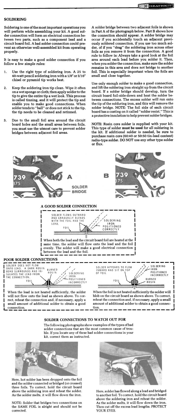
[Responses: Philip/James Abercrombie] We had intermittant AC problems on our 94 940 turbo that were cured by resoldering bad solder joints on the control board (behind the switches). As usual you need a magnifying glass to see the bad solder. Ours looked OK, but had a dark circle around the outside and black marks on the PC board from overheating. Re-soldered it and saved $300 for a new one (there are no service parts for this unit.) Two key areas should be examined closely: the connector joints and the relay (black box in center), especially the compressor connections. The solder cracks at the points where the high current load is passed through the PC board connections.
[Tips: Patric Paul] The faulty solder spot is in the lower half, a little to the left. Take your time and you will get it done. Don't overheat the circuit board while soldering.
[Response: Brian Oliver] The A/C failure was caused by the solder joint between the AC relay and the CCU controller's circuit board, as suggested. All this stuff is integral with the CCU control panel in the dash. Once you have the panel on your bench (or kitchen table in my case), remove the black plastic cover to expose the circuit board mounting screws, take out the circuit board. In the middle of the circuit board there is a black plastic box, probably the largest component there.This is the main relay which switches the compressor clutch current. On the solder trace side of the board, you may find barely visible cracks in the solder holding this part's pins to the copper traces. Mine was easy to see, but I do know that they are not always so: it was an open circuit at one of the larger legs of the box on the board. I enlarged the solder pad by scraping off some solder mask to allow greater wetting area, which I think will help prevent future failures. Once you find suspicious solder, you need to reflow the metal with a soldering iron until it is smoothe and shiny, possibly adding a but more solder while you are at it. The small electronics soldering iron may not be powerful enough, but be careful you don't over-do it if you use the big gun-shaped tool. Be especially careful that all the new solder you add doesn't form a bridge to the surrounding traces. Use a desoldering braid to remove excess solder. Reassemble, install in car, and enjoy. These HVAC control panels can be fixed as long as you don't need parts. They are at least as repairable as Bosch relays. They are sturdily built, too, except for this one badly designed trace on the circuit board. I am a physicist by training, but years of working in failure analysis in the telecommunications industry tells me that the solder joint in question is under-engineered.
Replacement Relay. [Randy Duke] If the solder joints are fine and the relay is malfunctioning, replace it with a Z2570-ND costing about $1.50 plus $2 S/H via USPS first class mail from digikey.com. The old relay is 9V and has a 190 ohm coil resistance, with a current load to the A/C clutch of about 4 amps though the contacts. The replacement relay has a coil resistance of 225 ohms so slightly less current is needed to activate it. The contacts are rated at 10 amps.
Temperature Control Selector Not Operating . [Tip from Allan Hewick] Problem: temperature selector knob inoperative. Knob controls the distribution shutter servo motor behind the glove box. I looked all around the board with a magnifying glass and then found the very small section of burnt out / broken wire, circled in red in the image to the right. Burnt / broken section of circuit board in red box goes from MCC pin #1 solder connection to another solder connection for a resistor (or something) and then into the maze of connection within the circuit board. In the green wiring book, pin #1 appears to have no direct connection to the servo motor control the shutter for air temp, but it ultimately connects to ground. Solution: I took a single copper filament from a wire and soldered it at each end where the burnt wire was connected, marked bypass. Multimeter now showed good continuity between the 2 solder points. Imagine my surprise when I put it all back together: the MCC works perfectly!
Vent Control Selector Fails; Prevents A/C Operation. [Tip from Jason R] Symptom: I've resoldered the MCC unit and still cannot get 12 volts to the low pressure switch. [Solution] After re soldering and replacing the relay i still had no luck in
getting the A/C to function by  kicking the compressor on. I checked wiring
and everything in between and all was working as it should. i have 2
spare MCC units, a later one with a "Snow Flake" logo on the A/C button and an earlier unit with an "A/C Off" button. Both
were otherwise identical. I took a good hard look at how this A/C button actually
functioned. I noticed it relied on the Vent Selector knob in the middle of the controller which
controls the vents and defrost. After turning one of the units to
defrost i heard the compressor kick. It still would not kick with the
A/C button, so I took the complete knob assembly from the other unit which i
determined to have a bad electronics board and put it in the one which
kicked on when in defrost mode. This required unsoldering the 2 black
or red wires ( depending on whether the unit is the "Snow Flake" or "A/C Off button" ) and re
soldering them to the other board. I installed the unit once more and it
worked! When all else fails it could
simply be the Vent Control selector that is preventing the A/C button to
function.
kicking the compressor on. I checked wiring
and everything in between and all was working as it should. i have 2
spare MCC units, a later one with a "Snow Flake" logo on the A/C button and an earlier unit with an "A/C Off" button. Both
were otherwise identical. I took a good hard look at how this A/C button actually
functioned. I noticed it relied on the Vent Selector knob in the middle of the controller which
controls the vents and defrost. After turning one of the units to
defrost i heard the compressor kick. It still would not kick with the
A/C button, so I took the complete knob assembly from the other unit which i
determined to have a bad electronics board and put it in the one which
kicked on when in defrost mode. This required unsoldering the 2 black
or red wires ( depending on whether the unit is the "Snow Flake" or "A/C Off button" ) and re
soldering them to the other board. I installed the unit once more and it
worked! When all else fails it could
simply be the Vent Control selector that is preventing the A/C button to
function.
ACC Heater Control Not Working.
[Inquiry:] Re 1987 765T; while at the dealer getting a new transmission put in, I also had them install a new heater control valve. The automatic climate control system will not put out any heat, at any setting...even with defroster on. The dealer believes the problem is a vacuum connection in dash. The heater control valve is not getting vacuum. Previously I pulled the glove box out and checked the vacuum hose and shutter doors there...they seem fine. The A/C works fine. Dealer says it is about an hour's labor to look in the center dash to find the vacuum problem. Can I do this myself? [Response:] Several things could have happened, most likely because the dealer who put in the new trans broke a vacuum line or crimped one somewhere...if you had heat before the trans was put in! There's a plastic vacuum reservoir underneath the car, passenger side, up front near the radiator, and should have a hose line leading to the engine and one leading to passenger compartment. Check for vacuum at the engine line and at the line leading to the passenger compartment and the ACC control unit, usually through a T connector. Fix as necessary. You might try putting straight engine vacuum or vacuum pump to line going to passenger compartment (there are check valves somewhere too, it IS a turbo engine!) and see if that actuates the heater valve/flappers. The actual vacuum switch is pretty reliable, but I've had to replace the climate controller/computer on my 87 764T. If the vacuum terminal plugs leak, see this tip.
Air Conditioning Failure. Note that the ACC system may also suffer from the same PCB solder joint failures as the MCC unit above.
ACC Climate Control Instability.
[Inquiry] Recently I have noticed that my climate control has a new personality; in fact, several of them. Our early Spring days in Charlotte sometimes require heat, and sometimes a/c. My trouble is that the hvac system delivers heat, then coolness, then nothing, then more unpredictability. This happens when set to a temp or total heat or total cool. What's more, the system's ability to select the right venting for defrost, heat, a/c, etc. has also gone mad. Anyone had this problem, or recognize the symptoms? [Response: Abe Crombie] The manual on this version ECC contains no troubleshooting charts. It only has the list of fault codes. The fault code list contains no fault tracing either. Any fault codes that would impact temp regulation would make the A/C button flash on start up and this was not mentioned
Does it not provide heat if you go to absolute last stop HOT and cold air if you go to the absolute last stop COLD? These end points override the temp sensors. The temp knob being set to either full end point should make system default to the respective mode. If this isn't happening then the servo that moves temp door needs inspection. If the temp goes to the proper mode at end points but not in any other temp setting (normal operation as opposed to end point defaults).
ACC Temperature Sensor Not Operating.
Blower Motor Ambient Temperature Sensor:
[Inquiry:] When its cold out, usually around 50 degrees, the air conditioning works OK. When its warm out, it doesn't work at all. No fan, No a.c. I assume its one of the sensors, probably the one on the dash. Its a 3 wire affair with a small lens in front. The other one is in the ceiling light, but I don't think that's the one giving me a problem. Any suggestions?
[Response: Abe Crombie] The solar sensor is not going to cause anything to fail
to function on that system. It only makes the system go slightly colder when
it's sunny. It sends no signal anytime it's dark outside. The sensor next
to blower motor may be at fault. Turn the air distribution knob to face vent, the temp
to full cold, fan in AUT, a/c switch off, and recirc on. Now punch the a/c switch
on and then off and count the flash code, punch a/c switch again and repeat
reading two more times. This will give any fault codes that are present in system.
The sensor can be bad and give no code as the system doesn't know it is defective
as long as it gives a reading that is within -50F to 180F. If it says it is
60 deg out when it is 96 the control unit doesn't know it is a bad reading.
Location of Ambient Temperature Sensor:
[Steve Oakes] Remove your glovebox and lower plastic shroud under the glove compartment. The sensor is mounted on the air plenum: it has wires running to it and removes by twisting 90 degrees.
ACC/ECC Interior Cabin Sensor:
[Tip from Mike Sullivan] Just a heads up for those of you with ACC systems. My '93 960 had been holding cabin temperatures lower than the level set on the dial (at least for heat, where 72 was more like 66-68 over the last year or so). For a while I thought this was going to be a problem with the dash computer or some other complex piece of the automatic system. Some had suggested that it was likely to be the sun sensor located on the top right of dash at the speaker. On studying the system more, I settled on the most likely problem as being the temp sensor located in the overhead dome light fitting, where there is a little hole and air is sucked in past an electric sensor. Note that there were no fault codes showing. Just before I ordered a new sensor, I found the answer - dirt collected in that tube in the dome light leading to the sensor. The fix turned out to be a couple of squirts of an electrical contact cleaner into the small hole where air is drawn into the temp sensor in the dome light. The excess runs out, and in my case, brought out a bunch of black dirt/ dust that was insulating the sensor.
ECC Climate Unit Not Operating. The ECC climate control unit in 960/90 cars can suffer from the same solder board cracks as the MCC unit above. Symptoms included irregular compressor operation. In addition, the solenoid valve controller, mounted under the dash in the passenger footwell just after the evaporator, can also have these cracks. Symptoms include both irregular compressor operation and vent doors closing at random, not correlated with acceleration. The solution is to remove the units and resolder the boards. The former is in the upper dash above the radio and the latter is identified by seven or eight vacuum lines and an electrical connector. If you cannot control temperatures, check your dome lamp sensor unit shown directly above for dust and dirt.
ECC Climate Unit Diagnostic Codes.
The ECC climate unit in air conditioning-equipped cars can detect certain system faults and display the appropriate diagnostic trouble code by flashing the lamp in the A/C button. If the control module detects one or more faults, the driver is warned by the flashing A/C button. If a fault is major, the lamp will flash continuously while the engine is running; if minor, the lamp will flash for 20 seconds after the engine is started. To read the diagnostic trouble codes, the engine must be running; the blower selector in AUTO setting; the function selector in VENT setting; the temperature switch set to maximum cooling; the recirculation switch pressed in; and the A/C switch released (out). Shine a strong light on the solar sensor in the dash speaker; otherwise, the DTC for the sensor will be displayed even if fault-free. Retrieve the DTCs by pressing the A/C button in and releasing it within 5 seconds. If several DTCs are stored, they will be displayed sequentially. All will be erased when the ignition is turned off. If no faults are set, then 1-1-1 will be displayed. Note that faults may be in the component or in its wiring.
To diagnose cars with ECC but without air conditioning, no trouble light will illlumine; the system will fail. Remove the ECC module from the dash panel, take off the cover plate and press the diagnostic test button twice within 5 seconds. Read the DTCs from the nearby LED lamp, pressing the button after each DTC to read any more codes.
Table of ECC Diagnostic Trouble Codes.
[Fault Classes: A: Serious; M: Minor; I: No warning to driver]
| DTC | Fault Component & Description | Fault Class |
| 1-1-1 | Fault-free | |
| Ambient temperature sensor (on blower housing): | ||
| 1-2-1 | Short-circuit to ground | A |
| 1-2-2 | Open circuit or short-circuit to 12V | A |
| Interior temperature sensor (in roof light): | ||
| 1-3-1 | Short-circuit to ground | A |
| 1-3-2 | Open circuit or short-circuit to 12V | A |
| Coolant temperature sensor (in heater): | ||
| 1-4-1 | Short-circuit to ground | M |
| 1-4-2 | Open circuit or short-circuit to 12V | M |
| Generator: | ||
| 1-5-1 | D+ signal level in generator | A |
| Solar sensor (in speaker grill) | ||
| 1-6-1 | (Note: illuminate this with a lamp to clear code) | I |
| Servomotor/potentiometer: | ||
| 2-1-1 | Open circuit or short-circuit to ground | A |
| 2-1-2 | Short-circuit to 12V | A |
| Servomotor Drive: | ||
| 2-1-3 | Pin 17 or 18 connected incorrectly to 12V | A |
| Servomotor: | ||
| 2-1-4 | Motor activated for too long > 10 seconds (blocked motor or failure of motor supply) |
A |
| ECC Control Panel: | ||
| 2-3-1 | Faulty temperature control | A |
| Blower Motor: | ||
| 2-3-3 | Starting current too high, motor seizes or turns sluggishly | A |
| Power terminal incorrectly connected to | ||
| 12 V for the solenoids as follows: | ||
| 2-4-1 | Water valve | A |
| 2-4-2 | Bi-level | A |
| 2-4-3 | Vent | A |
| 2-4-4 | Recirculation | A |
| 2-4-5 | Defroster | A |
| 2-4-6 | Floor | A |
| 2-4-7 | Maximum blower relay | A |
| 2-4-8 | Compressor | A |
| 2-4-9 | Blower relay (cars with air conditioning) | A |
| 2-4-9 | Engine cooling fan relay (cars without a/c) | A |
Vacuum Servos:
Panel Vent Stops Working Upon Acceleration.
General Notes. [Inquiry:] My friend has a '94 960 and the air stops blowing from the vents while the car is accelerating (the a/c fan is still spinning but no air is coming out) when ever the car reaches a steady speed it starts blowing again. The same thing happened to me in an '90 760t and it turned out to be a hole in the vacuum line that goes to the vacuum reservoir. However I can't locate the reservoir in this car. Does anyone have any ideas?
All: General Diagnostics. This is usually a result of a vacuum leak, whether it be an interior hose or servo motor, in the engine compartment, or at the vacuum reservoir. Find the vacuum line that goes to the vent diaphragm (vacuum bellows) under the dash behind the steering wheel. Uplug it and stick a vacuum gauge into the line using a "T". The vacuum should read engine vacuum at idle. Then accelerate the engine: if vacuum drops, your vacuum check valve may be bad. The vacuum gauge should keep a high vacuum reading when you accelerate. If the check valve and tubing under the hood are fine and the vacuum reading still drops, you have a leak under the dash, most likely one of the 4 bellows. The electronic solenoids in ACC/ECC-equipped cars and the vacuum reservoir appear to be more robust and don't give out that often. The rubber caps on the reservoir (in older cars located behind the front bumper) and rubber tubes under the hood have been known to fail
Look For Vacuum Failures Under the Hood First. [Response] First check the black/white vacuum check valve mounted at the top edge of the firewall under the hood above the cylinder head. This part is very cheap. In order to check the valve, just remove it and blow into both sides gently. If air goes through only one way then you are fine and this isn't the problem. If air goes through in both directions then you have a bad check valve. If it sticks or malfunctions, it causes the a/c vent to stop acting on acceleration. It can mimic the failed servo problem noted below. [Tip from Bob] Next check the vacuum supply hose under the hood. The vacuum hose for the A/C-heater can be found under the intake near the trans dipstick tube. Look for a small (1/8" diameter) flexible plastic hose. It goes from the firewall near the heater hoses and winds its way to a tee with a vacuum check valve connected to a larger hose, ending at the intake. It is common for the hose to rub through from chafing on other hoses or wiring harnesses. When you find the leak, cut the hose and splice with a small piece of rubber vacuum hose. Then check the passenger cabin side of the same hose, which can be crushed where it exits the firewall or behind the control head where there is a Y fitting in the source vacuum hose. Repair it with a piece of the rigid little spray tube that comes on aerosol cans like WD-40.
ECC-Equipped Cars: Bad Underdash Check Valves. The small vacuum check valves can fail. One valve feeds the ECC system and the other feeds the inside temperature sensor in the dome lamp assembly. Part number 9134341-8, each costing about $11.
All: Try Cleaning the Air Intake. [Tip from Larry Jacobson] Before doing any cutting and sawing, your arm up into the air intake that goes up in back of the glove box. You may be able to feel bits of plastic or paper or other light foreign matter that has been sucked into the system and is causing the flappers to not close. The vacuum motors huff and puff and hiss trying to slam the doors on the accumulated crud. I've had to do this twice and both times found all sorts of stuff up in there. My wife has a habit of clipping coupons in the car. Bits of paper fall to the footwell and some get sucked into the AC system. Makes a racket like baseball cards in the spokes of the old Schwinn bike.
All: Diagnosing the Vacuum Motors. [Inquiry:] My heat/ac won't come out my vents, it will come out the defrost and the floor vents, but not my regular vents. [Response: Dick Riess] The vacuum motors are located on the drivers side. You need to take down the portion under the dash and kick panel against the radio area. These are not easily replaced (if that is what is wrong), but through a shortcut suggested by Tom Irwin and receiving some of my mods, I have done one on my 91 940SE. It is kind of the Don Foster approach, in his case replacing the heater motor on 240s. There are 3 motors and fortunately the most accessible is generally the culprit and has two hose connections. First try a Mighty Vac and hook up a tube to each of the connections and see if they hold a vac. If one doesn't, you have a bad vacuum motor. Have to disconnect the hoses on the motor first, of course. Do your diagnostics first.
[Response: Abe Crombie] To expand on what Dick posted: The likely culprit, assuming the vacuum supply is coming in correctly from the engine compartment, is the floor/defrost servo. It is a double acting (no vac centered= floor/defrost split, vac on blue hose = defrost, vac on yellow hose = floor) and has a boot on the floor side that retains vac on that side of diaphragm. The boot fails and you lose vac. Blocking yellow hose fixes it simply with compromised floor air volume (floor would be floor/defrost). All of this aforementioned stuff is usually the case if symptom is loss on acceleration. [Editor] A new vacuum servo costs around $60 if you choose to replace it.
740 or 760: Tips. The 760 with ACC has an electric vacuum valve set to left behind glove box and a cold soldered joint on it at one of the end pins will cause no response in any position which defaults to floor/defrost. The 740 with MCC has a rotary vacuum switch linked to slide lever for vent selection and the hoses behind panel (white is source) can be crushed or the feed hose (white) above accelerator pedal at firewall can be crushed. The 760T with ECC has a floor/defrost servo sprung to return to center when no vac is applied. This will direct air reaching this part of the air distribution housing to the defrost and to the floor outlets. The yellow hose applies vacuum to the side of diaphragm that will extend the servo rod to push the door up blocking most of the defrost vent air and directing 90% +/- to floor. The seal that rides the servo rod can dislodge or just split and you have the result you observed: air stops coming out of any vents during turbo boost (manifold pressure instead of vacuum), indicating a leaky push-pull vacuum servo. Disconnecting the yellow hose will not allow you to get full floor air. When the floor air position is selected (by you or by the ECC logic) the air will be split between floor and defrost. This is likely not a problem unless you have really poor leg circulation that gives you a severe tendency to cold feet long after the rest of your body is warm. The logic in the ECC always has the floor position selected on this servo when it is directing air to the dash face vents so if it leaks you lose the vac for entire system and all the doors go their respective sprung positions.
960/90 With ECC: Tips. [Tip from Steve Long for 960 ECC] If you have done the tests above and you are still having a problem while in recirculation mode, try to pinpoint the cause to a specific vacuum motor. With the recirculation on and the controls set to max fan speed and dash vents, accelerate until the air no longer flows from the vents and then put your hand down under the dash to see if air is flowing from the floor vent. If this is the case, then the recirculation vacuum motor is likely leaking. [Tip] In a 960, you can pop off the panels on either side and put a clamp on the recirculating bellows (orange hose)and drive the car and see if the problem is gone or put a clamp on the floor side of the bellows (Yellow hose IIRC), or both (as in our case), and see if it goes away. If it does, the respective solenoid is at fault. The vacuum reservoir located behind the glovebox may also have a leak (common problem on this model). Unfortunately, in their infinite wisdom, Volvo opted to make the canister part of the evaporator case (VERY expensive). I replaced mine with a separate and independent canister. Any good A/C shop can do this. You can also just permanently cap off the offending vacuum line (probably orange or yellow), although you will lose some functionality. Remove the glovebox to locate the vacuum junction box with the lines installed.
All: Replacing the Vacuum Motors. Tom Irwin and Dick Riess developed a shortcut method requiring cutting the driver's side inner kick panel. Another technique is listed from Beka at Brickboard. Both are in the FAQ reference document.
Punting on the Fix. [Tips from GregV and John Sargent] Assuming the problem is not the under hood vacuum check valve, it is probably a leaking vacuum servo. After reading the FAQ's I was tempted to go under the dash and tear everything apart. However, I talked to the guy at the volvo dealership and he recommended a less then perfect solution. The servo valve that is going bad is the dual action vacuum servo on the outside of the heater box used to control the recirculating air function. Access is above the driver's right foot: take down the panel above the pedals and the knee deflector. You can check it by removing the yellow vacuum line from the servo and applying vacuum to the nipple on the servo. It probably won't hold vacuum. Replacing the servo is almost as much work as (ugh!) replacing the heater core. If you simply plug that one vacuum line as shown in the photo right, the recirculating function will not work, but the rest of the system will work fine. He asked me how many times a year I actually use the recirculate button, and if it was worth 4-6 hours to tear up my dash. He made a good point, so consider this as another option to actually fixing the problem.
Replacing Vacuum Servos in ACC-Equipped 700/900 Cars See the file link for more information.
Homemade Cabin Air Filter. [Tip from Rafael Riverol] My '95 960 has sucked enough tree leaves, pine needles, etc. through fan blower air intake and into evaporator chamber to turn into dirt, grow mold, blow out air vents and block drainage for evaporator condensation. To stop this, I bought a Shop-Vac 3 inch Reusable Dry Filters and Mounting Ring (Shop-Vac P/N 901-07) at Pep Boys for about $5. I suppose it can be found through www.shopvac.com too. The bag contains three large sheets of filter paper, one sturdy plastic ring and one large rubber band. I took one sheet of paper and cut from the edge one round piece with a radius about two inches larger than the plastic ring (or four inch larger diameter). Put this round piece of paper over the air intake and pushed the plastic ring down over it (narrow end down). Perfect fit! Of course, one has to remove windshield wipers and that plastic drainage channel to get to the air intake. I will cut the rest of the sheet of paper to fit over air intake inside the car (below the glove compartment and behind plastic trim) to hold it in place with the large rubber band. Two more sheets of filter paper are left over for future changes. I tried the A/C with the blower set at maximum speed and the paper filter looks like it will remain in place and not blow into the squirrel cage. For a 740/760/940, I think one could use the filter paper with the rubber band that comes in the bag. In my 760 I have put a flat (grease) filter with a plastic grid backing from a stove hood, wedged between that brace tube and the rubber lip for the air intake and held with a couple of zip ties. With the plastic grid facing down, the filtering element is kept from being sucked into the squirrel cage. [Dick Riess] This idea works for 960 cars; it would also work on the 940 SE as it is basically a 960 body. The air intake is similar.
Climate Control Aftermarket Replacement [thanks to Ernest Smith]: Visit http://www.programainc.com/default.aspx
Diagrams. Selected parts and assembly diagrams for the HVAC system are shown below.