
Replacing Vacuum Servos in ACC/ECC-Equipped 700/900 Cars
OEM Manual Procedure for Replacing Vacuum Servos. See the FAQ file for a large .pdf describing the official procedure with diagrams, courtesy Volvo Car Corporation (copyright; all rights reserved).
Replacing the Vacuum Servo on 700/900 with ACC/ECC Double-Acting Servos. [Procedure from Dick Riess, to whom thanks are given; some notes from Dan]
The following is a shortcut for installing the replacement vacuum valve involved with this problem. It is assumed that the old valve has proven faulty. Tom Irwin led me through my replacement and I feel the information can save much time and money. Tom Irwin did his on a 960 and I did mine on a 940 se. Basically it will include most 7 and 9 series that have that double acting valve. Believe this tends to be in the automatically controlled heating-ac cars. They all look alike from my studying the manuals. Warning! You cannot overestimate how long this job will take you. Leave plenty of time to go to stores for extra bits and pieces. Do not attempt with a sore back or hangover.
Tools required
- Small hacksaws. Pointed saw works best for starting cuts.
- Drill, approximately 1/8 inch.
- 10-mm socket to disconnect old valve and install new valve.
- Sidewinder 1/4-inch drive socket.
- Mirror to see where mounting nuts are located.
- Masking tape to line inside of 10-mm socket to hold nut in place.
- J-B Weld or similar substance.
- Black silicone RTV for caulking.
- Black or other color duct-tape.
Arrange car with the seat back. Pad the area with blankets to prevent bodily injury. Remove under-dash cover and bolster.
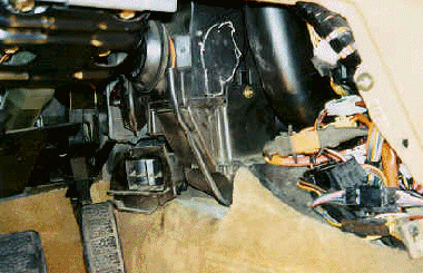 Picture #1 - Mark the area to be cut. Note the box in the picture and chalk marks. These are on the left side of the box.Drill 1/4-inch holes at the top left, top right, going diagonally up at approximately 45 degrees. Drill another hole, bottom left and another hole on the right side of the box. Cut across side-to-side. Next, make a vertical cut, and swing the plastic flap to the right side.[Note: I would enlarge the hole in the photo downward another 4 cm to have more room to maneuver.]
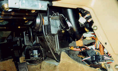 Picture 2. The plastic is quite flexible and may crack, but should not break, thereby creating a hinge. Note: if it cracks off, use duct tape and epoxy to repair. Take the hacksaw and cut to the left, horizontally, on both top and bottom, and swing the plastic flap to the left. Place a rag in the bottom of the hole to prevent bits falling down.
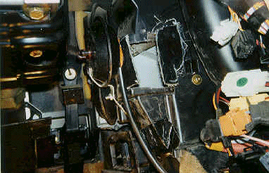
 Picture #3 - You now have access to the inside of the box. The vacuum valve is located on the left outside of the box and has two hose connections.Remove the hoses, and mark them for re-assembly. Next, using a 10-mm deep socket, and the Sidewinder ratchet, remove the two mounting nuts. These were a pig to get off. I used a 1/4" ratchet with a universal joint extension stiffened by wrapping it in duct tape. Next, remove the press-on retainer from the air-diverter post which holds the vacuum valve: this requires pushing and pulling with a screwdriver. Remove the vacuum valve.
Pictures #4 and #5 - In this picture, you can see the valve attachment to the air-diverter and the valves without hoses.This is also a picture of the new valve installed. Before installing the new valve, install the nuts on the valve to cut threads into the plastic stud. Don't break off the studs, which are brittle. Now install the new valve, without the nuts. Attach the valve to the air-diverter post and replace the lock piece. Next, replace the nuts on the new vacuum valve. You may need to use some masking tape inside of the socket to hold the nuts in place to prevent them from falling out. Be careful putting these nuts back on as the plastic studs may break.
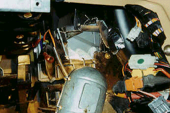
I am now going to assume that you have broken one or both plastic studs on the vacuum valve. You will need to fabricate a bracket, as noted in picture #4. Bracket material is the same material as used to mount car radios. This has multiple perforations and is fairly easily bent. Tom Irwin experienced breaking both studs and fabricated a bracket which held the valve on by going over the vacuum valve. The bracket had a hole in the center, which was enlarged, to go over the center hole of the vacuum valve. The bracket was attached to the air-box by using small screws. The bracket I used had a small bolt going through the box. Make certain that wherever you mount the screws that they cause no interference with the movement of the diverter in the air-box.
Attach vacuum hoses. Start the car, and check that the valve works properly by moving your heating-air-conditioning controls. If all is well, clean up the edges of the flaps which were cut, bend them back into position, and use J-B Weld or a similar product to hold in position. Next, use the black RTV-silicone sealant. Do not use too much as it could interfere with inside air-flap movement! After the sealant is dry, you may desire to put duct-tape over the entire incision. You will note in Picture #6 the reassembled unit minus the duct-tape. This has worked well for us during the past months.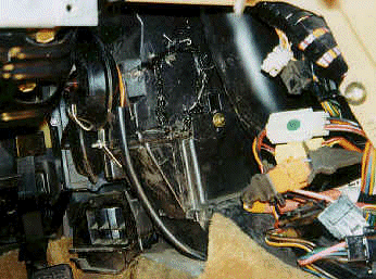
Replace the bolster and any other parts that were removed. Enjoy your air-conditioner.
Alternative Technique for Replacing Vacuum Servo
Similar symptoms in my 940SE: very little was coming out of the face vents during acceleration. I pulled open the inside panels and tested all accessible vaccuum motors with the pump and meter and found the double acting motor (the only one with two hoses) was leaking on one side. This motor is according to the manual the foot/defrost motor (part number 9463042).
This is how I replaced the vacuum motor:
Tools good to have were: Screwdrivers Torx T15,T20,T25, Phillips #2, Long nose pliers for the washer thing, mirror and flashlight, 1/4" Ratchet and spinner sockets: 7,8,9,10,12 mm, 6" extension, and for the nuts on the motor .. 4" flex extension bar (Steel cable type from Craftsman) together with a kind of thumb wheel spinner (Snap-On)
- Turn power seats as far back as possible.
- Remove ground terminal from battery (You do have the radio code later?)
- Remove knee covers on both sides.
- -Remove glove compartment (4 screws)
- Remove knee bolster at driver's side (2 screws , 2 nuts)
- Remove knee bolster bracket (2 bolts)
- Remove ashtray -Slide parking brake cover back 4-5" (6 screws)
- Remove switch cover right of steering wheel (disconnect switches and light)
- -Remove radio, compartment under radio and the whole radio compartment ( 4 screws, wires for cig lighter + 2 panel lights )
- Lift relay assembly to right side (plastic inhex screw)
- Remove the ECC control console (4 screws)
- Remove driver's side side feeding duct (round 90 degree behind radio compartment driver's side)
- Slide off duct feeding passenger side (carefully with force)
- Remove duct coming from air distribution housing to upper face and side vents.
- Remove air grilles (both sides) from floor distribution box (2 #2PH screws per grille).
- Disconnect temp sensor at driver side heater housing, disconnect one connector passenger side and check for others obstructing floor distribution box.
- Remove fixing screw for floor distribution box
- Driver side floor duct was soft and tin plastic and could be bent enough (again carefully with force) to get it off the floor dist. box.
- Once driver side of floor dist. box is loose it can be pulled back and slightly right.
- Now the double acting motor can be accessed through a down facing opening.
- Pry washer off lever (washer will brake) unscrew the two nuts and vacuum motor comes out.
- Mount new motor and test them all with pump and meter.
- Reassemble in reverse order.
Well I'm not sure which one is faster , easier or better but I had hard time getting the motor out and back in again even if I had an opening about 4*5" to work through. It took me 4 hours work to get it done. Care should be taken not to break many of the numerous plastic clips and tabs that keep everything fixed. Most time went to find replacement lock washer and to puzzle the ducts back together (a lot harder then to get them out). The procedure is not to recommend for people with bad backs, short nerves, or large hands. Noticed also that this one was the easiest to change , the other two ( single action ) would require the complete air distribution box to be taken out.