Front Suspension
Maintenance:
Wheel Alignment and Spring Sag
Component Replacement:
Control (Radius) Rod Bushing Replacement
Sway Bar End Links and Bushings
Troubleshooting and Upgrades:
Steering Pull to Left or Right
Front Crossmember Failures: Fatigue Cracks; Starter Cable Shorts
Upper and Lower Chassis Braces
Rusted and Stuck Bolts: Removal Techniques
Maintenance:
Wheel Alignment Basics.
- Camber is the angle of the wheel, measured in degrees, when viewed from the front of the vehicle. If the top of the wheel is leaning out
 from the center of the car, then the camber is positive; if it's leaning in, then the camber is negative. If the camber is out of adjustment, it will cause tire wear on one side of the tire's tread. If the camber is too far negative, for instance, then the tire will wear on the inside of the tread. If the camber is different from side to side it can cause a pulling problem. The vehicle may pull to the side with the more positive camber.
 - Caster. When you turn the steering wheel, the front wheels respond by turning on a pivot attached to the suspension system. Caster is the angle of this steering pivot, measured in degrees, when viewed from the side of the vehicle. If the top of the pivot is leaning toward the rear of the car, then the caster is positive, if it is leaning toward the front, it is negative. If the caster is out of adjustment, it can cause problems in straight line tracking. If the caster is different from side to side, the vehicle will pull to the side with the less positive caster. If the caster is equal but too negative, the steering will be light and the vehicle will wander and be difficult to keep in a straight line. If the caster is equal but too positive, the steering will be heavy and the steering wheel may kick when you hit a bump. Caster has little affect on tire wear.
- Toe. The toe measurement is the difference in the distance between the front of the tires and the back of the tires. It is measured in fractions of an inch in the US and is usually set close to zero which means that the wheels are parallel with each other. Toe-in means
 that the fronts of the tires are closer to each other than the rears. Toe-out is just the opposite. An incorrect toe-in will cause rapid tire wear to both tires equally. This type of tire wear is called a saw-tooth wear pattern as shown in this illustration. If the sharp edges of the tread sections are pointing to the center of the car, then there is too much toe-in. If they are pointed to the outside of the car then there is too much toe-out. Toe is always adjustable on the front wheels and on some cars, is also adjustable for the rear wheels.
Alignment Tips:
Camber: [Tip from John O] Volvo's revised this procedure in their latest suspension manual (several years old now) and IF you're presently in a shop and on an alignment rack, it's easier than that. While on the alignment rack and doing the alignment, you remove the front upper strut nut (holding the upper strut plate to the body), then take a hammer and pound the stud out of that plate. Loosen the rear nut, then adjust the camber by rotating the the top of the strut plate about the rear bolt using a pry bar until the camber is right (you can get it perfect), then drill through the upper strut plate using the front body hole as your template and install a new bolt and nut. Reusing the pressed-in bolts may be difficult; I used standard hex-headed ones. I've done it many times and it's a piece of cake, but I wouldn't even consider messing with this unless you're actually the technician doing the alignment yourself. [Response: Phil Bradley] There is another way that may be easier for some people. Remove the strut and slot one of the two tower mounting holes. I usually slot the forward one; the strut can pivot on the fixed rear one. No need to change anything in the strut top this way. You are still limited in the amount of negative camber you can get -- not much with stock ride height (maybe half a degree each side). With lowering springs, the geometry changes so that you can get a bit more (maybe 1 degree each side).
Caster: [Editor] Caster is adjusted by replacing the control arm strut rod. The standard length (distance between the centerline of the rear bushing and the front of the rod) is 390.5mm; the shorter version which reduces caster angle by 0.8 degrees is 385.0 mm and the longer which increases caster angle by 0.8 degrees is 396.0 mm.
Toe is adjusted by rotating the inner tie rod within the outer tie rod end to pull or deflect the wheel in the desired direction.
Specifications. Wheel alignment angles for 740/760/780/940 cars are:
| Angles | 15 inch wheel | 16 inch wheel |
|---|---|---|
| Caster | 5° +/- 1° | 4.5° +/- 1° |
| Camber | 0.1° +/- 1° | 0.1° +/- 1° |
| Toe-In Angle | Toe-in angle: 18' +/- 8' | Toe-in angle: 18' +/- 8' |
| Toe-In Distance* | 2.2mm +/- 1.0 | 2.3mm +/- 1.0 |
* when measured from left to right from rim center to rim center, front and rear of wheel
Wheel Alignment and Spring Sag.
Anecdotal experience from Brickboard indicates that spring sag in Volvo 700/900 cars is endemic and occurs most often in the rear springs or on the driver's side of the car.
[Tip from Servicing Coil Springs, Brake and Front End Magazine, Jan 2000) It's imperative that  you make a ride-height check part of your pre-alignment inspection along with all the usual ball joint, tie rod, tire, and other examinations. Specs can be hard to find in repair manuals, and OEM methods of checking ride height are not always easy. While you will occasionally find a broken spring, or someone who wants an upgrade, the main reason that you'll be replacing springs is to restore lost ride height. Ride height is critical to proper alignment angles, both front and rear.
A vehicle that sags in the rear may also increase front caster angles. This is because the sagging rear effectively moves the top pivot point of the front suspension (upper ball joint location on a control arm-type suspension) rearward, which obviously tilts the steering axis rearward, increasing caster. Furthermore, uneven ride height across the vehicle (left to right) can cause a steering pull.
Don't forget that a sagging rear spring can also cause a ride height change in the front of the car. Careful measurements are needed at all four corners because it is possible for just one spring to be weak. This can cause a ride height difference diagonally, where the left rear corner, for example, is low, the right front may actually be high. Volvo recommends that ride height be checked at each of the four jack point bars and that it not vary by more than 1/4 to 3/8 inch from one corner to the next.
[IPD] If your tires or wheels differ at each corner or tire pressure is not identical, eliminate their effects by measuring instead between the fender lip and the wheel center as noted in the photo at the right. Measure each wheel and then compare as noted above.
Wheel Balance. See the FAQ file for information about wheels, rims, tires, and balancing.
Control Rod Cone Bushings. [Tips from Randy] There are some symptoms to make you want to check the cone bushings. Some of them are difficult to sense just as with worn shock absorbers- the real difference is only felt when they are replaced. Symptoms that you WILL notice (other than those already discussed):
- 1) A squeaking when the suspension is at long travel such as when going over a speed bump at slow speeds.
- 2)A clunking knock, with matching feedback through the steering wheel when turning at slow speeds with the steering at full lock, particularly when on a dirt or gravel surface.
- 3) Eventually when the suspension is in a long-travel situation, the squeak will turn into a clunk like hitting a solid chunk of wood with a mallet. When you hear the squeak it is time to check the cone bushings. The squeak is the rubber against the control arm. It happens because the rubber is worn, compressed, and worn. As soon as it begins to move (causing the squeak) its wear will rapidly increase causing poor handling, uneven breaking, accelerated tire wear, and can eventually lead to a very unsafe and even dangerous situation.
Need to Replace All Bushings? [Tips from John Kupiec:] I recently rebuilt the suspension of my 744T. Since the car was 13 model years and 167K miles old at the time of rebuild, I anticipated a complete bushing replacement, and planned accordingly by purchasing a complete bushing kit. To my surprise, the only bushings that required replacement were the control rod bushings. All other bushings tested out fine in the pry bar test. 45 minutes of up close and personal inspection with two sets of trained eyeballs and a pry bar showed all bushings (even the rear link bushings) to be fine, with the exception of the strut rod bushings. What we did find was one strut rod with significant corrosion on the front end, significant enough to merit replacement of the entire strut rod.
Suggestions: 1. If you have the opportunity, put the car up on a lift and perform a bushing inspection before you buy replacements. If possible, do it with someone who is experienced with Volvos and 700 series in particular. 2. If you do not have the opportunity to follow suggestion 1, make sure you purchase your bushings from a retailer who will allow you to return the ones you do not need (Thank you, IPD!) Information I have obtained from other 700 series owners is that replacement of the strut rod bushings is almost a certainty. Replacement of other bushings depends on the age of the car, road conditions, driver's habits, etc.
Component Replacement:
Front Suspension Parts:
- Radius rod rear bushing nut: 88 ft-lb +/- 22 ft-lb
- Radius rod front conical bushing bolt: 70 ft-lb
- Control arm inner arm-to-frame bushing: 63 ft-lb
- Ball joint-to-control arm nut: 44.4 ft-lb
- Ball joint to strut tube: 22 ft-lb then angle-tighten 90 degrees
- Tie rod end nut: 44 ft-lb
- Sway bar end link top nut: tighten so that the outer flats of the washers are 42mm apart.
- Sway bar end link bottom bolt (if so used): 63 ft-lb
Strut Components:
- Top strut large center shock nut: 52 ft-lb for 1985 + vehicles; 111 ft-lb for 1984- with the center nut cover
- Top strut small nuts (2): 36 ft-lb for 1985+ vehicles; 30 ft-lb for 1984
- Large round gland nut: tighten to around 50 ft-lb by estimate; use liberal amounts of antiseize
Aftermarket Part Quality. [Editor] Brickboard has a growing number of reports of substandard suspension part quality, usually from Chinese-made components. All the major parts makers source globally and often have higher and lower-price point brands. Here is one report about a comparison of 240 tie rod ends from Federal Mogul's TRW and Moog parts lines:
[John Orrell] Differences I've found between the TRW and Moog parts despite the fact they have the same corporate parent:
Outer ends:
- Country of origin: TRW, China; Moog, Germany(box from USA)
- General casting quality: TRW, slight bubbles; Moog, nice but not perfect
- Grease fittings/approach: TRW, sealed; Moog, grease nipples included
- Fastener to wheel assy: TRW, nut with nylon lock; Moog, castle nut and pin
Overall: TRW, low cost, no margin in design; Moog, worth the extra money
Inner tie rods(CAM design):
- Country of origin: TRW, China Moog, Germany (box from USA)
- Overall appearance: TRW, good Moog, good
- Details: TRW, no flat faces, vise grip installation, Moog has flats for a wrench
- Accessories: TRW, tie rod in a bag Moog, detailed instructions
thread locker tube-o-goo and a lock nut
In conclusion, although I believe the damage to the TRW tie rods was caused by "wickedly bad roads" and an aggressive driving style, it is clear out of the box that the old Sears (good, better, best) quality scale from the 70s and 80s is at work here. I'll give TRW parts a (good) rating, and Moog parts a (best) rating.
[Editor] I have noticed similar differences, with lesser known or unbranded components showing the worst quality. Let the buyer beware on rubber or urethane parts (hoses, bushings, etc.), radiators, safety-critical items (ball joints, tie rods, etc.) and most other items. It is still true that Volvo OEM parts are at the top of the quality chain. Some are sourced from TRW but made to higher standards.
Control (Radius) Rod Bushing Replacement. [Editor's Note on Symptoms Evidencing Need for Replacement: See Brakes Pull When Applied]
Detailed Procedure for Control Rod Bushing Replacement.
[Editor's Note: This four-piece conical bushing set is the big wear item in your front end. Usually this is all that is required; the rear control rod round bushing does not wear as quickly.
[Tips from Rod Johnson] I noticed that my 740 had steering looseness and the condition of the strut rod bushings was bad. Both sides were badly split, and the right side was extremely sloppy in the lower control arm. I could move it about a half inch, just by pushing on the wheel.
So to the main crux of this post (how to replace the conical bushings) I found a strut rod bushing kit on a well known internet auction site, and for $51 delivered, I was ready to install them. I've not done this before on a Volvo, but I do have many years of experience working on automobiles in general. It took me just over an hour to complete the job, after I had the car on the stands. You will need two long breaker bars (one about 18" minimum) and a 22mm and a 15 mm 1/2" drive socket. A ratchet will speed things up when you finally get the bolts loose. A pry bar and small hammer may also be useful.
Jack up the car and place it on jack stands or other suitable supports under the control arm (not the strut or radius rod). All work is done from under the car, and considerable force is needed to get the bolts to come loose, so if you consider yourself a bit on the 'weak' side, get a 24" breaker bar. You do not need to remove the wheels or any other parts. The rear end of the strut rod is a round bushing with a bolt going through the frame mount and the bushing. The nut is probably coated with undercoating, so you will need to clean some of it off to get the 22mm socket over the nut, or just hammer the socket over the undercoating like I did.
The head of the bolt is a 15mm hex (and again heavily undercoated on my car), so you will need a second socket, or long box end wrench (don't even think of using an adjustable wrench on these-you will need a very good fitting socket. If you have a 6 point socket, find it and use it). Again, the undercoating is the biggest issue here.
Brace yourself against the frame of the car and break the nut loose, then use the ratchet to get it off the bolt, and make sure the bolt is loose in the bushing. If it is corroded, you will need to get it free before attempting the next step.
Now go to the front end of the strut rod, and look where it comes through the lower control arm. Under that gob of undercoating, is another 15mm hex bolt, which screws into the end of the strut rod, clamping the bushings into the strut rod.
Using the long breaker bar and the 15mm socket again, remove the bolt and outer bushing. Now remove the rear bolt completely from the frame mount. Pry the rear end of the strut rod down and out of the mounting bracket, and slide it to the rear and out of the control arm. Remove the remaining half of the front strut rod bushing. Don't forget to clean out ALL the residual old bushing material: you may need a chisel as the old rubber is often stuck to the control rod. There is a metal core to the bushing that needs to be removed as well. Use a rotary wire brush on a drill to gently clean things up (watch out if you have aluminum control rods). Then be sure to clean the threads of all the nuts and bolts using a wire brush, just in case there are some deformed threads or rust. When reinstalling, use some 'Lock-tite' (or other brand) bolt retainer on this mounting hardware. On the replacement bushings, usually the part numbers go toward the large support washers.
Now replace the strut rod, with the new bushings, back into the lower control arm, and get the front bolt started. Then pry the rear bushing back up into the frame mount (you might need a small hammer or mallet here) and pry it forward to line up the bolt hole with the mounting bracket. Insert the mounting bolt, install the nut, and tighten both the front and rear bolts.
[Tip from Hakan Carlsson] When the bushings are in place compress them slightly by screwing in the bolt without the washer. This will make it easer to actually fit the washer, since it otherwise will be a little hard to start the thread. Use some force to push the radial arm into place. It takes a little patience but it works.
[Tip from JohnB] Here's a useful trick if you can't get that end bolt to start with the new bushings in there...take off the bolt that holds the sway bar link to the strut control arm (same thread...longer bolt!) and use that bolt to start/compress the new cone bushings. Then unscrew the long bolt and put the correct bolt in with loctite
[Tip from Paul] After replacing the strut rod bushings (also known as cone bushings because of their shape) it is better to lightly snug the fastening nuts while the front end is supported off the ground. Then lower the front end back to earth and tighten the nuts to the specified torque. The reason for doing this is so that the bushings can find their sweet spot or neutral setting in the position that they will spend 99% of their time in. If you torque them up with the front strut arms hanging down and then lower the car to the ground it is possible that there is tension in the bushings as the load of the car is put on them. This is probably something you would never feel driving the car, but it could contribute to decreased bushing life.
Do the other side the same way and take it for a test drive. I will be willing to bet the steering feels quite a bit more precise. You are done with your part, but now you need to contact your local friendly alignment shop to have the alignment set again, as it is probably in need of a bit of adjustment. You have just saved yourself about $100 in labor and parts costs.
[Tip from W Bain] Once the new ones are in, lower the car and tighten to specs. I've got the Volvo green manual for our cars and the torque specs are: Bushing, washer and bolt for control arm: 95 Nm - 70 Ft-Lbs Then rock the front end a few times, torque the rear nut and bolt to 85 Nm - 63 Ft-Lbs.
More Tips.
[Inquiry on 89 745T:] What's the best procedure for replacement of the front suspension radius arm bushing with minimal disassembly? I simply removed the sway bar end link (replacing them anyway) and the bolt holding the control arm to the radius arm. So I was obviously able to get the front conical bushing out (man, was it trashed) and now I can't get enough play to clear the tube from the radius arm where it goes through the control arm. Do I remove the radius arm from its rearward mount (to the chassis)?[Response] You have to remove the arm.
[ Inquiry 2: ] How about the chassis end?[Response] The rear bolt has to come out. It is the only way to get the rear bushing off.
[Inquiry 3:] If I am replacing struts and balls joints, is it better to remove the CONTROL arm instead of the RADIUS arm? Is it more likely that the control arm's chassis side bushing is in need of replacing vs. the RADIUS arm's? [Response] Control strut bushing (the conical $20 bushing, two each per side) is the one most likely to need replacing. BTW, IPD sells the whole front end bushing set for $130 or so...if you're replacing four conical bushings for $80 and your car has over 100k on it, you should just bite the bullet and buy the IPD bushing kit and do them all. However, it's not trivial to replace the other front end bushings (much like the rear) - you need a press.
[Tip from Warren Bain] If you round off the radius rod rear bolt, replace with a 9/16 3" bolt which will work for the rear radius rod attachment point. The combo was about $4.80 for the set, nut, bolt and two washers. SAE quality only, no lesser quality will work since they might break and cause loss of vehicle control.
Grease on Bushings?
[Inquiry] Should I apply grease to the bushings?
[Response: Don Foster] Do NOT put grease on rubber components. Oil-based grease will quickly damage rubber bushings. I'd only add that you can grease the outer metal sleeves where they slide into a bracket or mating fixture, such as with the large trailing arm bushings-grease the metal-to-metal interference fit. It might ease the installation. Also, you can grease a bolt that slides through a metal sleeve-it might make disassembly easier ten years from now when you redo the bushings.
[Response: Jim Baron] The point underlying the first two responses: rubber bushings are not supposed to move or slip at all against metal surfaces: they are designed to absorb the various twisting and compressing forces imposed on them within the body of the rubber itself. If you grease the area where the rubber meets the metal, you create a sliding friction situation which will wear out the bushing very rapidly.
Weird Bolt Heads.
[Inquiry] The head of the strut rod bolt towards the rear is a 6-point star -- an inverse Torx head (looks like a giant Torx bit)! A 13/16" 6-point socket fits the nut end, and a 14mm wrench fits this weird star head, but I decided to abandon the job for fear of stripping the thing.[Jim McDonald] Go ahead: they will work.
960/90 Series Control Arm Bushings. Unlike 740/940 cars, in the 960/90 the rear bushing on the control arm is the one that frequently fails. If you don't have the tools to replace the rear bushing, you can inexpensively replace the whole arm. They're fairly easy to replace. Get the proper ball joint separator if you're planning on reusing the old ball joints. If you decide to get the whole arms I'd recomend against using Scan-Tech brand as I haven't heard many good things. Buy the Meyle arms instead of Scan-Tech.
Sway Bar End Links. [Editor] Note that the rubber bushings in your sway bar end links will crack and wear. It makes more sense to replace the entire link, due to likely corrosion, than just the bushings. Note that there are two styles when ordering: the photo from IPD illustrates the differences between the early 4-piece link for steel control arms and the later 8-piece link for aluminum control arms. When installing the new bushings, tighten the nuts so that the distance between the top and bottom of the outer washers (the surface next to the nuts) is 42mm. Note that some reports of sway bar end link failure have occurred, all correlated with cheap aftermarket parts. This may be another instance in which the dealer-sourced OEM part is much more reliable.
To Replace The End Links: [Editor] Jack up the car and remove the front wheels. Unbolt the top of one sway bar end link (the sway bar will pop upwards). Remove the link, replace either the entire rod or just the bushings, and reinstall the bottom bolt. The bushings are installed with the little cylindrical protrusions pointed toward the hole in the sway bar. Using a floor jack under the control arm, lift the arm and guide the new link end into the hole on the sway bar, then reinstall the top bolt. Don't forget the top bushings. Lower the jack. Now do the other end link. When reinstalling, use the jack under the control arm to raise the assembly so it goes into the hole in the sway bar.
Urethane Bushings? [Editor] The little rubber doughnuts on the end links will flatten over time. Urethane bushings last much longer, albeit at a cost of a little more vibration transmitted through the sway bar. See below.
[Inquiry] I bought a set of front control arm strut poly bushings for my 86 740 Turbo from FCP Groton. Trying to install them today and have a couple problems. The bushings are supplied with a steel tube that's about 60 mm long. The original bushings, when placed together, have a length just less than 50 mm. It would appear that the compressed length of the poly bushings will be about 10 mm too long. Also, when I put the new bushings in, with new steel sleeve, the bolt in the end of the lower arm is too short to engage the threads in the end of the arm. I think a longer bolt would work, but I'm still concerned that the length of the bushing from washer to washer will be too long, forcing the control arm (and the whole wheel/strut) forward, altering the wheel alignment. Has anyone tried this successfully?
[Response: Vince] You are correct on your observation of the control arm being pushed forward. I quite a while posted similiar to yours and got replies questioning my discovery. I got mine from IPD, they were blue urethane, and thicker than the originals. I put one side on, decided I didn't like way it altered my steering geometry, took them off, sold them to someone else. I don't know why they were designed so much thicker than stock, other than to induce a change in alignment. Since both sides move forward the same amount toe settings shouldn't change. What will change is caster, whether you want it or not, by adding positive degrees. I don't know if this is desireable. Those that have installed them say they notice a difference, which could be partly due to the geometry change as much as to the difference in the material of the bushings. I found this note on the GAPA and All OEM websites describing their urethane bushings: This bushing is used on vehicles that have had had the control arm stays and related bushings replaced with service units designed to reduce brake vibrations. The length of these replacement control arm stays (#6819079) is 388.5mm.... If you look up the stock rubber bushings it has this note: This bushing is used on vehicles with factory original control arm stays. Depending on model and wheel size, these control arm stays can be of the following lengths: 385mm, 390.5mm, or 396mm. Stays that are 388.5mm in length are replacements with a special inner bushing designed to reduce brake vibration. Cars with 388.5mm stays should use outer bushing #6819057 instead. It seems to me that the urethane bushings are meant to used with shorter stays(or torque/radius rods) because of their additional thickness and were never meant to be used with the 390.5mm ones that came on our cars. I believe the urethane bushings carried by GAPA are the reds. The IPD blues are even thicker.
Installation. [John Sargent] Some installers have found it difficult to install the PU bushings using the stock control rod bolt. It is not necessary to install a longer bolt. Use a longer hardware store bolt for installation only. The longer bolts are needed just to get the assembly of the new cone bushings started. Then re-use the existing bolt, which is a special grade necessary to keep your suspension intact. [Raidman] Or just buy a one centimeter longer bolt in 8.8 grade. [Note from IPD] Use the bolt in the kit instead of the original for the installation as the replacement inner metal sleeve is a different diameter than the stock one.
Need for Strut Replacement. See the brief discussion of shock absorber wear in Rear Suspension.
[Comments from Ken Dibnah] I spent part of a day replacing the front struts on my 940 SE with a pair of Boge Pro Gas that I bought from IPD. When last visited, I had replaced my Nivomats (I have IRS) and lo and behold, I found that not only had I realized my hope of a more controlled/compliant ride, but the rear end stayed where it was supposed to, following the front end obediently instead of hanging wwwaaaaayyyyyy out on wet, powered corners (myself being somewhat confused in my expectations as I returned to the world of rear drive from my 2 year sojourn amongst those who are pulled through life, I thought those swings were part of the charm of the car).
Results were disappointing at first - didn't see too much improvement on the test drive, and the car sat an inch or so higher in the front , I think. Seemed smoother, but not remarkably so. Difference really showed up on the drive home. Had to do some serious braking, (to avoid an SUV!) and the control was remarkable. Usually, wet, heavy braking had the ABS hammering away, and not anymore! Wheels stick to the ground and don't hop about like they used to, cornering is much flatter, and rough roads (like the camel track known as the Stanley Park Causeway) are actually bearable again - the glove box stays closed and you can hear the radio!
So get out and change those shocks. The 'bounce check' just does not reveal flaws. If your car is high mileage your shocks are worn out, even if it 'bounces' as it is supposed to. My old struts, you could just push 'em in and pull 'em out, no damping. The shafts were polished like glass with no machine marks visible. They aren't visible and they are expensive, but shocks have made the most remarkable difference in the car's handling. Change those shocks! (I don't sell 'em, by the way)
Tips, Tools, and Procedural Notes. [Courtesy of Jim Burton, via Joel Reiter's Volvo homepage.]
Tools:
You will need spring compressors, a good set of 1/2 inch drive metric sockets, a 3 pound sledge hammer, Loctite Blue, a large pipewrench, and the remainder of a good tool chest. Also helpful are an impact wrench (for removing the top strut nut), a garage jack for raising the front frame cross-member, and a quality jackstand. There are some odd sizes of nuts and bolts underneath: 18mm, 24mmm, etc, and some of them require deepwall sockets. Finally, you will need to make astrut holder to keep the strut from falling. Buy an 18 inch long piece of 3/16 threaded rod. Bend one end into a 4-inch deep hook with a 3-1/2 inch diameter. Bend the other end down into a short hook at 90 degrees, one inch long. The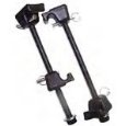 tool is nine inches long. Use the large hook around the strut; affix the short hook into the sway bar end or a body cavity to hold the strut. (UK, OZ, Canada, Euros, etc.: one inch=2.54 centimeters. Sorry: we're strange. SAFETY NOTE: Compressed springs can go off like a bomb if a spring compressor fails. The best plan is to use THREE for safety and ease of removal. Don't use a worn or obviously failing spring compressor at all and be careful of Chinese-made junk.
Tips:
Here are the areas and potential parts needs you should watch for (not in any special order).
- Use Loctite Blue or an equivalent thread locking compound on all suspension bolts. Consider replacing some of the critical nuts and bolts if you have high mileage.
- Parts: In addition to the struts themselves, if you have 70K or more on the car (7x0 series only), you will need to replace the bushings on the rod that fastens into the lower a-arm. If you are well over 100K, consider replacing all your ball joints while you have the front-end apart as well as new strut mounts, strut mount bearings, and sway bar end links or bushings.
- Have two strut mount bearings handy in case you need them. You can always return them to Volvo if you don't use them. The yellow side goes up, or in any event it fits snugly into the recesses of the strut mount and spring seat, flat side next to the strut mounting plate. If you don't change them, at least lubricate them with chassis or bearing grease. [Editor:] If you lose a few balls, buy an all-new set (about 45 loose ball bearings); the closest English size is 3/16 inch.
- Mark the strut top bolts and plate so you don't mess up the front end alignment. Outline the circular cutout with a felt-tip marker, and mark a cross where the two front and back bolts emerge so you can replace them with no alteration. Note that the strut plate is directional and has a front side.
- Look at the top mounting plate rubber bushings and the rubber spring isolator and make sure the rubber is not cracked or brittle.
- Unbolt the brake line bracket on the inner fender so the lines have more flexibility. There is no need to disconnect a brake line from the caliper. Pop off the wire holder on the backing plate for the ABS sensor for the same reason.
- Support the bottom of the strut with a garage jack so that the brake line is not under tension. Use a strong bent steel rod holder to keep the strut from falling when it comes out of the car: one side should be in the shape of a "u" and the other a hook to fit into the sway bar end hole. A coat hanger is NOT robust enough: try some 1/4 inch rod from a hardware store and bend it to fit.
- You will need a hook spanner or pipewrench and PBlaster to get the top gland nuts off the strut tubes.
- When removing the strut and spring assembly, the upper strut bearing can come apart, spreading ball bearings all over your driveway. Sweep the area first so you can find them.
- If your new struts come with straps, cut the strap as soon as you get ready to install. It's only there to make the shock fit in the box; the shaft won't come out very fast, and you can push it back without too much strain, though you won't need to.
- [John Sargent] Center the cartridge in the socket at the bottom of the strut before tightening the gland nut at the top. Some cartridges have a significantly smaller OD than the ID of the strut. If they are aren't centered, they will eventually work to the center and there will be slack and a clunk.
- If you decide to change the ball joints, buy new bolts and nuts that fix the ball joints on the lower rear shocks. The old ones are typically pretty rusted and beat up. Use anti-seize on the sleeve part of the bolts and Loctite on the thread.
- Torque all your suspension bolts/nuts to factory spec as you reassemble. The suspension bushings should be torqued after the car is on the ground.
- Take your time and don't let yourself get frustrated. Allow all day and celebrate if it takes you less time. A couple rusted bolts or a missing tool or two can easily turn a reasonable job into long job.
- Use jackstands and tire blocks (stop rolling) to protect yourself.
There may be a loose washer/spacer in the bottom of the strut tube. Make sure this goes back in exactly the same way it was before. If it flips to the other side, you will not be able to make enough turns on the top nut that holds the strut insert in the tube. This one took me forever to figure out what was wrong.
When disassembling the outer tie rod ball joint, take off the nut, apply some PBlaster, and let it sit for 15 minutes or so. Then whack it with the 3 pound sledge hammer. A few whacks should loosen it. If you can't get it that way, you must drive a balljoint separator between the a-arm and the ball joint. This usually destroys the boot on the ball joint, so have spares ($26 each) available. Use anti-seize on the new ball joints. After you complete the job, get it professionally aligned. Take some of that money you saved and do something fun the next weekend. After all, you just spent all day Saturday working on the car when you told your wife it would only be 4 hours tops.
Detailed Instructions:
Inside the engine compartment, you'll notice that the top of the strut assembly has 2 bolts which secure the strut/spring assembly to the chassis. These 2 bolts are all you need to remove to allow the assembly to drop down from the top and then swing outwards with its base still secured. Make sure you mark the location of the bolts with an x and outline the circular cutout on the strut mount plate so you do not lose your alignment settings. Use a permanent marker. [Photos by John Sargent] PAY ATTENTION TO THE INSTRUCTIONS and follow them closely.
BEFORE you remove these 2 bolts you'll need the following tools:
- a spring compressor which you should be able to borrow at an automotive parts store, and if that's not available to you, to rent from almost any rental shop. Or buy one from JCWhitney ($20 +s/h)
- an air impact wrench to loosen the large nut at the top of the strut or the piston rod. This nut is not impossible to remove with conventional wrenches if you have a box-end that'll reach deep enough to allow you to hold the top of the rod from turning. The impact wrench will handle the job without having to prevent the shaft (or rod) from turning. An alternative if you don't have an air tools, is to stop by a tire shop or any place that has air wrenches and get them to simply loosen that centre nut for you. Then you can take the car back home and, at the proper step, remove the nut with a wrench. You can do the same for the re-install and have them torque it down for you.
- You will also need a small floor jack, a good set of metric sockets (including 18mm) and wrenches; a large pair of water pump pliers or a pipe wrench; and a good chisel and hammer for undoing the special nut that holds the shock insert in the tube. I was fortunate to have a set of dropped box wrenches for the large top nut and a high quality crescent wrench.
- Unscrew the large nut on the top of the strut rod several turns before you do anything as it will make it much easier to undo it after it is out and the coil compressors are in place. Do NOT unscrew it all the way.
- Jack up the car, support it at the front jack points, and remove the front wheel. Jack it up high enough to allow the wheel assembly to swing down and to be able to place a garage jack underneath the ball joint stud. Place the jack under this stud to support the assembly as it drops down.
- Remove the bolts from the bracket that secure the brake hoses to the wheel well. Mine used a twelve point Torx, size 40 and yours may too. Remove the ABS sensor wire clip at the fender and free the sensor wire. Remove the brake line from the plastic holder using a putty knife to lever it out while pulling on the line.
- Loosen but do not remove the large gland nut at the top of the strut tube by lifting the rubber shield and using either the special three-pronged tool or a pipe wrench between the spring coils. Doing this now is much easier than when the strut is lying down.
- Disconnect the tie-rod end. Apply a little PB Blaster to the bolt shaft where it comes through the control arm hole. Let it soak for twenty minutes then, whack the side hard several times and it should drop out. I actually put the nut back on and tapped it several times and it fell out right out probably from the light coat of anti-seize compound I used when I put the tie rod ends in. If this fails, use an end link puller.
- Disconnect the sway bar link at the top. Now is a good time to think about new bushings for the link. There is no need to disconnect the control rod but if you do it makes it easier to push down the strut assembly.
- Secure a strut holder or a bent piece of steel rod or its equivalent to the middle of the strut assembly and to the car chassis inside the wheel well so that when you remove the 2 nuts from the engine compartment, the assembly is not allowed to swing out more than about a foot. Any more of a swing-out than that will result in damage to the brake lines and the fender liner. Place the garage jack under the ball joint stud and support it so it does not drop precipitously. NOTE: Some prefer to remove the entire strut assembly from the car (as in the photo above) by first removing the brake caliper and hanging it up. This may be required if the gland nut on the top of the strut is frozen in place.
- Place duct tape on the upper edge of the fender to protect the paint as the strut top swings out.
- Remove the 2 nuts inside the engine compartment.
- Swing the assembly down and out. You will have to manhandle the top downwards by pulling at the spring and pushing on the wheel hub enough with your foot to get it to clear the fender. DON'T HIT THE FENDER WITH THE TOP OF THE STRUT: consider taping several pieces of duct tape under the fender lip and installing a rubber bushing on the top of the strut rod. One technique is to place your foot on the brake caliper and push down while pulling on the spring. The photo shows how the assembly drops down and out from the wheel well. Drop the jack slowly to allow the assembly to first drop down vertically and then, as it clears the strut tower, to swing outwards.
- Compress the spring using the spring compressors to about 12 inches.
- Once the spring is compressed sufficiently to remove the pressure against the top plate, remove the large centre nut. Use an adjustable wrench on the flat sides of the strut rod and a box end wrench on the nut. You can now pull out the spring. [Additional tip from Simon] After the spring compression, make a record of the sequence of strut support, bearing and cover (and mark the top of the bearing so as not to reinsert it upside down), rubber mold, washer, etc. and which way they are positioned. It is easy to disassemble, but assembling must be in the right sequence and position.
 You can figure it out if you forget the sequence, but why waste the time.
 - With the spring out of the way, all that's left to do is to remove the large flat gland nut that holds the cartridge in place. A C spanner is perfect, although a large pipe wrench will do in a pinch or you can simply tap it unscrewed with a chisel. The photo shows two ChannelLock pliers being used to remove the nut. In difficult, corroded cases use heat and a large pipe wrench. Be carefull on the reinstall that you do not make contact with the piston rod. Treat it as if it were made of glass.
- Pull out the insert, put the new one in. Use antiseize on the gland nut for future removal! Simple as that. [John Sargent] Center the cartridge in the socket at the bottom of the strut before tightening the gland nut at the top. Some cartridges have a significantly smaller OD than the ID of the strut. If they are aren't centered, they will eventually work to the center and there will be slack and a clunk. [Randy Starkie] Don't mash the tangs on the gland nut so that they interfere with seating the nut fully in the threads. See below for tips.
- [Additional tip from Simon:] Consider lubricating the strut bearing using chassis or bearing grease. The strut bearing has loose ball bearings held with a cup/plate. The bearing assembly can be opened easily. If you do, don't lose the bearings: there are perhaps forty-five loose ball bearings inside, all in a metric equivalent of 3/16 inch, and they will fly all over. If you lose a few and have to replace them with loose bearings, buy a new set (don't mix old and new). Replace the assembly with the yellow side up. If it has a different color, make sure the bearing rests securely in both recesses: one side is rounded, the other is flat.
- Renew the rustproofing where you scratched it. Spray 3M tar sealant works fine.
- Reverse the process for reinstall. Insert the strut mount bearing 4 (if you removed it) into the strut mount 2 with the flat side up toward the mounting plate and firmly seated. Wipe dirt out of the spring top rubber mount recess where the bearing is seated. Make sure the spring top rubber seat 6 is on the spring correctly (the end of the spring is matched to the end of the seat recess), the top mount assembly is not out of alignment, the strut bearing 4 is firmly seated into the spring top seat recess, and the strut bearing and mount rotate freely. There is a large concave metal washer 3 that fits into a concave recess on the bottom of the rubber strut mount: make sure this is fitted as it is easy to forget (in the photo below, the washer is gold in color). Before releasing the spring compressors, install the large rubber washer 1 (Volvo 1273745: serrated edge down) and hand tighten the large center nut. Place duct tape on the strut top nut to prevent paint or fender well damage. Use the garage jack applied to the ball joint stud to lift the strut top tube through the hole in the mounting plate and load the strut assembly. When you do this, have a helper spot the shaft so that you don't misalign it and tear the rubber bushing inside the plate; you can watch the insertion of the sway bar end link into the sway bar from below. Reinstall the strut mount nuts on top and align the strut mount so the studs are in the proper position (as you marked them) to preserve alignment. When aligning the strut mount, use a rubber mallet and pound on the large center nut (NOT the alignment studs: these are pressed in and you will knock them loose). Torque to 36 ft-lbs.
- With the garage jack lifting the ball joint to load the strut assembly, tighten the large nut on top of the strut shaft. Hold the strut shaft with the Volvo tool or a wrench so it does not rotate. Torque to 52 ft-lbs.
- Install the tie tod end; the bushing, washer and nut holding the sway bar end link on the sway bar; the brake line holder, the brake line and ABS sensor wire if equipped. Retorque all, take one last inspection, and install the wheel.
Torques:
- Top strut large center shock nut: 52 ft-lb for 1985 + vehicles; 111 ft-lb for -1984 with the center nut cover
- Top strut small nuts (2): 36 ft-lb for 1985+ vehicles; 30 ft-lb for 1984-
- Sway bar end link top bushings: tighten so that the outer flats of the washers are 42mm apart
- Sway bar end link bottom bolt: 63 ft-lb
- Tie rod end nut: 44 ft-lb
- Wheel bolts: 63 ft-lb
One word of caution: treat the compressed spring with respect. If the spring compressor ever lets go, you have got a lot of energy to contend with.
Strut Tube Space/Washer Notes.
[Inquiry] I'm coming around to doing front struts again, and want to make sure I get it right this time. I have an 89 744T that currently has Boge Gas Turbo's on the front. The strange thing is that the top cap on the strut cartidge tube has several threads showing. Is this cap supposted to screw all the way down? This got me wondering whether or not I had spacers at the bottom of the tube. I just replaced the lower ball joints, and could see the butt of the cartidge but no apparent spacer. Should the top of the cartidge be flush with the top of the tube, or at some depth? How big is this spacer, and did it come with the OEM strut, or is it a fix for aftermarket struts? Does anyone know which struts need this spacer?
[Response: Abe Crombie] The strut top is normal to be as you describe it. The order should be special washer, bumpstop-boot washer, spring cap, bearing nut. Do a dry run w/o spring so you can see if the fit of the parts seems okay. The shaft of shock MUST HAVE THE SPECIAL WASHER THAT HAS THE CHAMFERED (bevelled) OPENING SO THAT IT FITS THE CORRESPONDING CHAMFERED EDGE OF SHOCK ROD 2 DOWN FROM THREADS. If you miss this part the shock rod may show up through your hood one day. [Editor] This washer is secured in the rubber tangs of the strut mount. I would use the bump stop if at all possible. The spacer is really a shaped retainer washer that rests against a snap ring at bottom of strut tube. Some after market shocks may use an additional spacer or a substitute spacer. The gland nut needs to be tightened to something in the neighborhood of 50 ft-lbs(more than a little tight, not get-a-hernia tight) and a pipe wrench or large channel locks would work.
[Response: Patrick Collins] The top cap on the strut cartridge tube will have several threads showing when installed properly. I just finished replacing my factory original cartridges last night (the cartridges had Volvo stamped on them), and several threads were exposed before removal. As a matter of fact, I had to soak the exposed threads with penetrant to remove the rust and dirt before removal. The cartridge was almost flush to the top of the strut tube, but not perfectly flush. The main thing is to make sure the new cartridge does not have any play when inserted in the tube and the cap is run down. Also, be sure to re-grease the journal bearings. Mine were in desperate need of grease.
Gland Nut Tips:
Seized Gland Nut. [Tip from P. Dwyer] Assuming you've tried PBlaster/similar product, pipe wrench, long lever, etc., might I pass along my perennial suggestion: heat it up, then (and here's the 'nutsy' part) TIGHTEN the nut, even just a few degrees: I hope you either hear a slight 'pop', or feel it, or both; then back the nut off. Not 100% sure-thing, but 99% ain't shabby. Also, there is a thing called a nut splitter, a tool that slips over the nut and is then tightened until a knife-like edge splits the nut. And finally, you can try a hacksaw or similar ploy. But whatever ya do, HAVE FUN, and wear safety goggles
[Tip from EPS] There is a way to remove these cartridges from the bottom of the strut housing, when the large nut at the top of the strut housing will not move. Remove hub/strut/coil spring assembly from vehicle. Place on workbench and safely remove coil spring and top bearing pieces. Remove strut cartridge from bottom of strut housing by first removing the lower ball joint from bottom of housing. Look into bottom and see circular snap-ring, lower support plate, and bottom of strut cartridge. Remove circular snap-ring carefully, and support plate will drop out with strut cartridge. Then the top nut on strut housing can be removed. I cut four slots downward with a hacksaw blade on the inner bore of nut at 0,90,180,270 degree positions. Be careful that these slots are deep enough, but not so deep as to cut into threads. Then hit the outside diameter of the nut at one of these slots, this will crush the nut inward, and allow you to remove the rusted sob. Clean the inside threads on the strut housing well before installing new cartridge and new nut, using antiseize on the threads.
[Art  Benstein] Damage can be caused by lack of counterhold for the gland nuts. In every case but one car, I've done the strut replacement on the bench, electing to disconnect and later bleed the brakes. Then, I have the assembly on a plank and can use a big hammer on a spanner for the gland nut while keeping the assembly on the ground with one boot. When I did the one car by leaning the struts out leaving the brake lines connected, it was fiddly to keep the lines slack, but my impact technique on the gland nut was done with the strut resting on a wooden box. Reasonably I should have broken them loose while still attached to the A-arm, but my previous success doing it on the floor left me without a thought of it. Also, I later looked at the Volvo manual to see the ingenious S-hook used to support the strut in this on-the-car technique. Considering it later, I worry the damage would be to the rack at the pinion, or even the column u-joints or steering lock, if excessive force or impact is used to free the gland nuts in place. An alternative might be some large pipe wrench to counterhold against brute force.
[Ryan] Our '91 apparently had the original struts still on the car.... so the gland nuts were waaaaaay stuck. I hit the gland nuts with everything ranging from fire (MAPP torch), to a BFH, to an air chisel. What worked in the end was not one pipe wrench, but *two* 24" pipe wrenches. Pull the strut tube off the car, put it on the ground, put one wrench (jaws up) on a 2x4 on the ground, and then put the neck of the strut tube in the jaws, so you can use the ground as a "counterhold". Then put the other wrench on the gland nut, and simply bounce all of your weight on the wrench. The gland nut *will* come out. One of my gland nuts came out with the threads from inside the strut tube. It was that stuck. If this doesn't do it, a salvage yard can provide a replacement strut tube.... hopefully on the cheap.
Bent Gland Nut Tangs Cause Clunk from Unseated Nut. [Lyle Risius] I had used the Boge replacement gland nuts and they are made so the
flat surface of the nut is bent to wrap around to the side and this is
the contact point for a pipe wrench or channel locks when tightening.
They are designed so that there is enough space for the bent over part
to wrap down around the strut mount tube. I had apparently applied enough
gripping force with my channel locks to bend this part inwards so that it
was hitting the top of the strut mount tube before it was fully seated.
Hence, the loose gland nut clunk. I pulled it apart, mounted a new
gland nut, and no more clunk.
Glad to have that fixed but more care at the start could have avoided the problem altogether.
960/90 Strut Replacement
Which Struts to Buy? [Jim E] We have two '95 960's. Mine has the OEM Volvo front struts, while my wife's has the Monroe struts. The Monroe struts are slightly stiffer, but not harsh in comparison. Both pairs of struts are about 2 years old, but I'm thinking of switching to the Monroes for the sportier ride. [John Roberson] I replaced both front struts with Monroe-car rides a lot better than on the OEM parts. The Monroes provide somewhat stiffer control and flatter cornering.
Strut Replacement Procedure. See the YouTube video for an overview.
Upper Strut Mounts and Bearings.While the upper strut mount does positively secure the strut regardless of the bearing condition, you can still experience a loose front end if the bearing is loose or unlubricated. The bearing is positioned with a moderate slip fit on the rubber under the mount. The rubber strut mount insert should not move up or down within the cylindrical sleeve or stretch too much.
[Inquiry:] After replacing struts, ball joints and all bushings, the front end still feels loose. I've narrowed it  down to the upper strut bearings. With a spring compressor, how big a job is this? [Editor] The procedure is almost the same as replacing a front strut, above. See the Strut section for more details and torque values. Note that strut mounts (not the bearings) are directional and have front/back orientations: the longer side of the oval faces to the front.
Part Quality. [Chris Mika] The best practice is to stay with OE Volvo, Boge, Bilstein mounts or OEM SKF brand bearing for replacement. The APA, Uro, and Scantech brands fail prematurely-- this is well-documented by users on other discussion boards. See the photo below of a failed URO mount which does not show collateral hood damage.
Bearing Mounting: Note how your bearing is mounted. It should fit snugly in the recess in the rubber strut mount with the other half in the circular well in the spring top mount. Try it both ways: the correct way will be obvious since it fits much better.
Bearing Lubrication: [Editor] The bearing is supplied dry, but I prefer to lubricate it with wheel bearing grease.
Strut Top Washer Note: some strut mount brands have an integral strut washer (about 1-1/2 inches/3.5cm in diameter) mounted under the bottom of the rubber mount: it is gold colored in the photo to the right. You can tell if this is so by comparing the metal washer, if any, on the new mount with your existing concave washer. It will be  concave in shape, the concave part facing downward, and have a bevelled opening that fits on the bevelled surface about two inches/5 cm below the top of the strut rod. DON'T double up these washers: you need only one.
Problem: Strut Rod Pierces the Rubber and Tears the Strut Mount. [Editor] This is almost always due to (1) forgetting to install the concave washer which serves to spread strut forces across the mount or (2) using a cheap aftermarket strut mount. If you have this problem, you will need new mounts. Fix it ASAP since the rod is highly likely to move upwards and right through the hood. See the photo above right for the gold washer correctly inserted into the rubber doughnut. See the photo to the right for an example of a URO mount, with washer correctly installed, that failed at 10,000km. This failure caused the strut rod to pierce the hood.
Diagnosis. [DougC] You can check the inner tie rod connection by raising the front of the car so one wheel is off the ground. Feel through the steering rack boots, but be careful: if they are really old, you might accidentally punch a hole in them. Feel at the exact spot where the ball and socket joint is. Have someone wiggle the wheel holding their hands at 9 and 3 o’clock. Feel for slop. There should be none. Study the tierod picture below beforehand so you understand the geometry.
Tools. [Question:]Are there any tricks to changing this? I suppose it's a good idea to change the tie rod ends with this job. [Answer:] It will take a few hours (if you're doing this first time), and you will need the following tools:
- A socket set; 21mm and 22mm open end spanners; locking pliers; a large breaker bar for extra leverage with stuck bolts; note that some US aftermarket brands use a 3/4 inch SAE nut, not metric.
- Car jack; Bottle jack (makes it easier - see text); good penetrating oil such as PBlaster; and a wire brush; Hammer.
I suggest you change both tie rod ends - First, if one is shot the other one is probably on it's way, and second - they're cheap. Change as well if the rubber boots are torn. You'll probably pay more for the tracking than you will for both ends.
Tie Rods:
The complete tie rod is made of two pieces. There is the inner tie rod which consists of the rod itself and the ball and socket joint where it connects to the steering shaft under the rubber boot. The rod part has threads at one end where it screws to the tie rod end. At the inner end it has the ball and socket joint that allows it to move up and down with the wheel movement, etc. The end of this ball and socket joint screws onto the steering shaft that is part of the rack and pinion system. The "outer tie rod" or "tie rod end" that connects at the wheel is the second part of the complete tie rod assembly.
The procedure is rather simple. You can remove either outer or inner tie rods or both. The rod end connects to the strut with a conical 'rod' locked with a nut, and the inner tie rod screws into the end and also has a locking nut.
Which Inner Tie Rod? [Editor] Thanks to Nick at FCPGroton, the photos below show the various rack and tie rod configurations you might have on your car. FCPG has them all. Some cautions from FCP: We recommend that you try to idenfity the brand of steering rack on your vehicle before purchasing the tie rods. The inner tie rods on these models are extremely difficult to catalog and identify. The first two images are of the CAM/TRW tie rods. Note how they are similar to the Koyo version tie rod in the third photo but they are not interchangeable. The third photo fits models with a Koyo rack from 1991-1995 on the LEFT side. If you have a KOYO rack, the rack will be stamped with the word "KOYO" and you may also see this word on the boo:t "Koyo". The fourth image is of the ZF tie rod. Note that you can identify this rack by the grommet on the shaft of the tie rod.
Nut Removal. First, jack up the side you're working on and remove the road wheel. Using the 21mm spanner, release the locking nut on the tie rod (the one that locks the inner tie rod to the tie rod end). The 22mm spanner holds the tie rod end itself if needed. This may be quite difficult, but since the end is still bolted to the strut, it will not turn so this is easier. Sometimes the tie rod turns with the nut, in which case:
- Use plenty of PBlaster penetrant
- Use the wire brush to clean the threads (probably a good idea anyway)
- Make sure you are turning in the correct direction (examine the threads)
- Use heat if necessary: place the inner rod in a vise or secure it from turning. Wrap the stud end of the tie rod end with a wet cloth to keep the grease and the boot intact and then using an oxy torch quickly get the threaded end to a dull red. Apply a pipe wrench and turn it out as quick as you can. Allow the rod end to cool slowly.
- Count the exposed threads so you can reassemble with approximately the correct wheel alignment
- Use the locking pliers to hold the tie rod, and release the nut
Inner Tie Rod. To remove the inner tie rod, you disconnect it from the tie rod end by loosening the locknut on the threaded portion of the inner tie rod and unscrewing it from the outer tie rod end. Count the exposed threads before you start so you can get it reasonably aligned when you reassemble. You don't have to remove the tie rod end at the wheel where it connects to the steering arm, but you will if you're replacing the tie rod ends also. Once this is disconnected, you can pull the boot off if you haven't already cut it off. Then you disconnect the inner tie rod from the rack shaft gear. Secure the rack gear shaft with an adjustable wrench so it won't rotate while you unscrew the inner tie rod end; if it rotates you will ruin the seals in the rack. There might be an obvious lock washer affair which is great, or there might be a peen that holds the inner tie rod from working its way off the shaft which would cause a loss of steering on that side of the car. The peen dents into a recession in the shaft that you won't see really well until the inner tie rod is off. If yours is the peened style like mine is, you'll have to decide how to get the peen out so you can remove the inner tie rod. I carefully filed mine off because I didn't want to beat on the steering system too much. The Volvo manual shows a guy removing it with a small chisel. If you file it, go very carefully. Otherwise you'll file down into the shoulders of the recession in the shaft and the new peen on the new tie rod won't have as secure of a lock. Hopefully, you've got the easier style with the lock washer and bent tab. You may have an inner tie rod with a circular end; to remove this, use a pipe wrench. Hold the rack with another wrench so you do not destroy the steering gear. When reinstalling the inner tie rods to the rack ends, sometimes they do not screw on all the way, stopping about two full rotations shy of where it should be. Apply moderate pressure with a wrench: the last couple of threads are sometimes locking threads that provide an extra lock to add to the peen. And use Loctite Blue to keep this secure. Before reinstalling the bellows, clean it out and apply a palm-sized dollop of CV grease on the tie rod ball joint and inside the bellows. Don't use non-rubber-compatible chassis grease.
Bellows. Replace a torn bellows by unscrewing the outer tie rod lock nut (below), then counting threads to the end of the outer tie rod (so you can replace it with alignment approximately correct). Unscrew the inner tie rod and the lock nut. Cut the bellows inner tie and remove the outer spring clip. Peel off the bellows. Clean dirt from the inner tie rod and apply fresh CV grease to the ball area. Fit and secure the new bellows, then refit the outer tie tod end. Align the front wheels.
Tie Rod Ends. Using a socket, release the nut that locks the ball joint to the strut. You can expect this nut to be quite stuck as well. If you let the steering rack move to full lock, you'll have something to push against. Remove this nut completely. The ball joint must now be removed from the strut. And, it will probably be stuck as well... So, just use the bottle jack to hold the strut - put it under the bits that the ball joint is in, as close as possible to the ball joint, and lift it a bit - just enough for the jack to take the weight. Then hit the stud on the ball joint - sooner or later, it will pop out. [Alternative removal tool from Doug Weiss: I fashioned a tool out of an after market exhaust system u-bolt type clamp. Open the u-bolt to fit the bolt holes in the lower ball joint (Strut removed). Bolt it on, using decent sized (thickness) washers, then slip a pry bar between the loop created and the control arm. No ball joint can resist the torque now at your disposal.] [Editor:] If the outer tie rod end is stuck on the tie rod and cannot be removed, change the inner tie tod. Remove the rack boot by cutting the plastic tie, unscrew the inner tie rod while holding the rack screw steady with a wrench (don't let it revolve). Replace the inner tie rod, the rack boot (use a heavy-duty cable tie) and then install the new outer tie rod end. Use antiseize on re-assembly.
When you have the tie rod end ball joint free, remove it from the tie rod, and count the number of turns. Then, put on the new one, with the same number of turns. This will set the tracking close enough so you can drive the car to the garage for an accurate alignment.
Put the ball joint in the strut, and tighten the locking nut (44 ft-lb). [Editor: I use a tiny bit of grease or antiseize on the ball joint shaft to ease disassembly next time.] The ball joint may turn in its hole, so use the locking pliers to apply a *bit* of pressure to it while you tighten. Once it 'catches' it's usually OK. Tighten the inner to outer tie rod locking nut - this time, use two spanners, one on the nut and one on the tie rod end. The easier method is only good for a ball joint you're about to throw away.
Refit road wheel, and repeat for other side - and that's it! You're done - but don't forget to have the tracking done.
Tie Rod Ends Rusted in Place: New Inner Tie Rod Needed
[Editor] If your tie rod ends are rusted in place and can't be removed, you will likely need a new inner tie rod (the shaft mounted on a ball joint inside the rack boot. Get one at an auto supply store, along with a heavy-duty cable tie for the rack boot. In my case, I jacked up the car, removed the tie rod end from the strut, crawled under the rack, cut the rack boot tie, pulled the rack boot back to expose the ball joint, and used an adjustable wrench to hold the rack at the gear while I applied adjustable pliers to unscrew the inner tie rod and ball joint. I have also used a pipe wrench on the style of tie rod with a circular end and no flats. DON'T allow the rack gear to rotate or you will ruin the rack. This freed the whole tie rod assembly, which I pulled off. I cut the inner rod with a hacksaw to remove the boot. Then I screwed the new inner rod into place on the rack end, using medium threadlocker, and staked it with a punch where the old one was staked. Clean off the boot and add grease to the rack gear, the ball joint and the inside clamping surface of the rack boot. I reinstalled the rack boot with a heavy-duty cable tie and the existing outer spring clamp and then installed the tie rod end. Ready for an alignment. BTW, the local NAPA parts store had my inner tie rod in stock for my '90 745 with CamGear. Make sure you get the right one with the correct length of both shaft and inner threaded portion. See the Steering section for help identifying your rack.
Test. [Import Car Magazine, Apr 2003] To check the ball joints for wear, have the vehicle resting on wheels. Using a large pair of pliers, squeeze down on the joint. The maximum axial play permitted is 0.12 (3.0 mm) and the maximum radial play is 0.02 (0.5 mm). Check the rubber boots; if they are torn or damaged in any way, replace them.
[Editor] You will need a deep socket set, a large breaker bar for leverage, and a garage jack, in addition to the ball joint kit which should contain not only the ball joint but two replacement bolts, a control arm nut, and a cotter pin as well. Because of stuck bolts, a six-point socket is recommended. Do not reuse the old bolts: they are torque-to-yield and cannot be reinstalled.
Removal:
Jack up the car and place a jackstand under the front jacking point. Turn the steering wheel so you can work on the ball joint from the front of the car. Remove  the road wheel. Examine the ball joint: it is bolted to the strut tube bottom and is pressed into the control arm, affixed with a nut and cotter pin on the bottom. Remove the front control arm strut rod bolt to free the arm (you do not need to remove the control arm from the car, but now is a good time to examine conical bushing condition). Remove the ball joint stud cotter pin and then unscrew the control arm nut holding the ball joint shaft (you will have to hold the shaft to keep it from turning). You can use a bungee to pull the lower strut assembly away from the control arm. Remove both bolts on the bottom of the ball joint: these will be tight and will probably require the large breaker bar to remove. Ball Joint Shaft. After applying penetrant oil, use a mallet to hit the control arm and free it from the ball joint shaft. Or use a puller as shown in the photo. [David Zipkin] If you lack a pittman arm puller, loosen the nut of the joint in question leaving it on a few turns to
protect the threads. Smack the side of the pin receptacle casting--in
the case of the tie rod be sure to smack the receptacle head on as it
extends from the spindle assembly for maximum stability. Sometimes a
second hammer or steel shaft is helpful to keep the swinging hammer/your
hands away from other suspension parts. The shock will usually loosen
the ball joint pin with one or two smacks. If you're removing the strut
take the tie rod first so as to keep things as solid as possible. [Jeff Pierce] A variation on this is to loosen the ball joint nut, then using two hammers hit both sides simultaneously. The shock will loosen the joint. Threads. The ball joint bolts are mounted in holes that extend through the strut mount end. The tops of these holes are open and can rust. If you need to tap the threads to free them up, use a 12mm x 1.75 tap.
the road wheel. Examine the ball joint: it is bolted to the strut tube bottom and is pressed into the control arm, affixed with a nut and cotter pin on the bottom. Remove the front control arm strut rod bolt to free the arm (you do not need to remove the control arm from the car, but now is a good time to examine conical bushing condition). Remove the ball joint stud cotter pin and then unscrew the control arm nut holding the ball joint shaft (you will have to hold the shaft to keep it from turning). You can use a bungee to pull the lower strut assembly away from the control arm. Remove both bolts on the bottom of the ball joint: these will be tight and will probably require the large breaker bar to remove. Ball Joint Shaft. After applying penetrant oil, use a mallet to hit the control arm and free it from the ball joint shaft. Or use a puller as shown in the photo. [David Zipkin] If you lack a pittman arm puller, loosen the nut of the joint in question leaving it on a few turns to
protect the threads. Smack the side of the pin receptacle casting--in
the case of the tie rod be sure to smack the receptacle head on as it
extends from the spindle assembly for maximum stability. Sometimes a
second hammer or steel shaft is helpful to keep the swinging hammer/your
hands away from other suspension parts. The shock will usually loosen
the ball joint pin with one or two smacks. If you're removing the strut
take the tie rod first so as to keep things as solid as possible. [Jeff Pierce] A variation on this is to loosen the ball joint nut, then using two hammers hit both sides simultaneously. The shock will loosen the joint. Threads. The ball joint bolts are mounted in holes that extend through the strut mount end. The tops of these holes are open and can rust. If you need to tap the threads to free them up, use a 12mm x 1.75 tap.
Installation:
Apply antiseize to the ball joint stud shaft where it sits in the control arm. Pull the strut away from the control arm and insert the ball joint into the arm. The triangular point on the base is toward the arm. Using your foot on the control rod, push the arm down while pushing the strut assembly over the new ball joint. Release so the ball joint cover inserts into the large hole on the bottom of the strut. Apply Loctite medium threadlocker to the new ball joint bolts and reattach the ball joint to the bottom of the strut tube. Torque first to 22 ft-lb then an additional 90 degrees angle tighten. Torque the strut rod bolt to 63 ft-lb and the ball joint nut to 44 ft-lb. Reinstall a new cotter pin. Fill the top of the ball joint bolt holes with rust preventative (tar) and apply this to the cotter pin as well. Reinstall road wheel. You may want to check the front wheel alignment after this procedure.
Control Arm Replacement. [Editor] Note that control arms come in two flavors: steel (earlier cars) and aluminum (later). They are NOT interchangeable and reflect suspension system design differences in mounting points and bushings. Buy the unit appropriate for your model. To replace the control arm, remove the sway bar link, ball joint and control rod per instructions above. Unbolt the arm from the inboard mount. To replace, install a new bushing with a press (Volvo OEM units come with the bushing installed), use Loctite Red on the nut securing the arm to the front cross member bolt, and torque to 85 Nm or 63 ft-lbs.
Troubleshooting and Upgrades:
Vibration in Front End. In the event of vibration in your front end which may be transmitted through the steering column, first suspect wheel imbalance or worn conical strut rod bushings. Worn struts, ball joints, tie rods, strut mounts or bearings, other front end bushings, or faulty tires can also contribute to this.
700/940 Series.
The two most common areas of clunkiness, if you will, on the 700 series are: Worn ball joint - Being ungreasable, these can deteriorate and cause the strut assembly to have play at the base of the strut cartridge. Not necessarily detectable through the bounce test but under vehicle load (dynamic), it can show up (audible). Correction: replace ball joint(s).- Worn/broken upper shock mounting - the large rubber doughnut inside of the mount can be split and there'd be no visible signs of it's demise except when removed. However, the warning sign of this is not usually a clunking under straight line driving or under the bounce test. It shows up under low speed cornering as a mild clunk at or close to full steering lock. However, my experience was that as it got worse, it did start to emit audible warning under driving load.
[Editor:] The upper strut mount bearing, located within this doughnut, can also fail and give clunky feelings, usually on steering hard to the stops. I have found that these can wear unpredictably; if your car has over 100k miles and you are replacing the struts, you might consider new strut mounts and strut mount bearings.[Barry Wilson] My clunk was due to the strut mount washer that is under the rubber strut mount and on top of the strut rod: this had worn oval. It was popping back and forth when the wheel was turned to complete lock.
[John Sargent] Have the strut cartridges been replaced? If so, some strut cartridges have a significantly smaller OD than the ID of the strut. This type of strut cartridge must be centered in the socket at the bottom of the strut. If they are aren't centered, they will eventually work to the center and there will be slack and a clunk.
[Editor] And check the large gland nut holding the shock insert into the strut tube: this can loosen and cause a "clunk" in the front end.
Note: the infamous bounce test is NOT an accurate way to pinpoint any front end/shock/strut problems. Remember, that as you are bouncing the front, you are really having to defeat the spring strength first (since they are what's holding up the vehicle under it's own weight) before any other problem areas will show up. This usually takes dynamic (moving) loads to recreate. Other sources to look at:
- The bushings, as you've mentioned. Usually, broken bushings can actually be seen as cracks at the visible edges. Not always detectable as such but worth a look.
- The strut inserts themselves. Once they've exhausted themselves (and perhaps have leaked their hydraulic blood, there's not much else to do but clunk against the side walls of the pistons.
- Sway bar bushings - if they are worn at the center mounts, the bar can be hammering the frame.
[Diagnosis comments, again on clunk in front end:] If your problem is not the spacer in the bottom of the strut tube, then it is time to start inspecting all of the front suspension. Check the sway bar bushings - both the ones at the end link and the ones that fasten the sway bar to the front frame rails. Check the control rod rear bushings - sometimes their deterioration is not evident and takes a large pry bar to see the problem. Also, inspect ball joints (they are spring loaded for wear, so need large channel locks to squeeze to check play), outer tie rod ends and also the inner tie rod ends, though these will probably not clunk when pressing down on front end. Try reaching over tire and putting hand around front strut while someone bounces front end to see if you can 'feel' the clunk. Did you already try tightening the big nuts that hold the shocks in the strut tubes? And if they are tight against the top of the strut, it is likely that you need to disassemble and install the spacers. When they are tight, there should still be several threads showing. Also don't overlook the upper strut mounts/bearings. If the rubber is cracked and pulling away from the metal bearing in the center, you need to replace them. Suspension is likely the problem, but also check the wheel and bearing. These are usually low speed clunks, but are potentially more dangerous.
Sorry to point out the whole blamed front end, but as I said, it could be anything... you just need to study each of the components and figure out which you want to attack first. If you have original shocks or just about anything with over, say, 50k miles (Bilsteins maybe higher mileage), I'd suspect the shocks first.
960/90 Series. [Inquiry]My 1996 960 Wagon (68k miles) developed a knocking/clunking sound on both sides on rough roads over the winter. [Response: J. Bowers/WilHome] Sway bar end links are a common problem with this design. Because they are connected directly to the struts they have to turn as well as carry suspension loads, so they are designed like miniature tie rod ends. Any rust & wear and they will be noisy. Mine failed after New England salted road water got into one. The part is an "outer stabilizer link" P/N 272991 same part number for both sides. List price is around $64 each. It can be replaced in about 30 minutes.
Steering Pull to Left or Right. [Editor] Steering pull is almost always due to either poor wheel alignment or spring sag.
Symptoms of Failure. [John Sargent] I've never had a front wheel bearing failure on a 700/900 with the late style hubs. I can tell you the harder you load the bearing, the greater the noise of a failing bearing will be. If you turn to the left, the right front bearing will be loaded higher, and it will make lots more noise, and vice versa. They can run a long time making noise you can't stand. [Ted Yaffo] Wheel bearings once they "fail" are unmistakable: the friction from their disintegration so dramatically increases you will get grinding horrible sounds and if left alone for not much time will render the car un-driveable and can even cause the hub to fail catastrophically. Look for to start:
- uneven tire wear
- jack up the front end and hold the tire at 3 and 9 o clock and feel for play; if there is any your bearings are loose
- a humming can heard as they begin to fail progressing to louder and louder sound
Later Two-Part Hubs . [Inquiry:] I would appreciate anyone's input as to experience with alternatives to Volvo's idea of spending 240.00 US in parts to replace a wheel bearing of the simple ball-bearing type. Aftermarket sources? Rebuilts? Bearing kits? [Response 1: John Kaiser] Your bearing or hub assembly is pretty expensive from the dealer. Unlike the earlier 740s these are not rebuildable. They do go bad once in a while. Check with a good import parts place because this hub you need is available through the aftermarket.
Earlier One-Piece Hubs. Take the bearing out and look on the side, you will see the bearing number. March off to the local parts shop, almost any will do and ask for a bearing of the same type number. You can start with the listing for Volvo and then make sure it matches the number you took off. There are not that many tapered bearing makers in the world and the local parts guys usually stock the individual bearings not the kits like Volvo. Done it many times on Volvos and MBs. Just reuse the other bits and pieces.
Reusable Parts? [Inquiry] Don't you have to replace the hub nut and grease cap with new parts when this is done? [Fitz Fitzgerald] The axle nut used on the later vehicles (with the sealed hubs) is supposed to be replaced each time it's removed. However, there's nothing special about the nut itself, other than the top is pinch narrowed. When the nut is installed, the top is forced to open up a bit, and provides a tight grip on the threaded shaft. Since the pinched section at the top is opened slightly in the act of installing the nut, Volvo advises replacing it whenever it is removed. (about $5 to $9 per axle nut) [Jay Simkin] Do not add lubricant to these later two-part hub bearings. Do not clean them with solvents - e.g. trichloretylene - which will damage the seals. Do not re-use either the axle nut or the axle nut cap. A torque wrench should be the only special tool that you need for installing the late model nuts. The early style require a bit more finesse and is similar to the 240 style and should require no special tools.
Replacing Bearings and Reinstalling the Two-Part Hubs. To reinstall the bearings and hubs and keep the inner race for the outer bearing from falling out, you can buy or borrow a race driver (a set of tapered aluminum pieces that fit the contour of the race, withe a hole in the back to index a round aluminum driver which is then driven home with a hammer until it is flush) or try a slightly easier approach. [Jay Simkin] Here's a way to make a removable plastic ring to keep pressure on the inner bearing race, as you move it along the stub axle. Take a plastic cable tie, 1/8" wide, and put it on the stub axle, 1/8" from the leading edge. Adjust the cable tie, so it is just short of snug, i.e., so it will slide along the stub axle, when pushed. As you lower the hub towards the stub axle, use your fingers to hold the inner bearing race in place (from inside, letting your fingers press on inner edges of the inner bearing race). When you have the opening in the hub, level with and centered on the stub axle,slowly pull out your fingers, and push the hub gently onto the very end of the stub axle. The cable tie will at once contact the outer edge of the bearing race, and keep it from sliding freely. Push the hub towards the strut housing. If the cable tie won't slide back towards the strut housing, move it 1/8" with your free hand. Step-by-step, work the hub onto the stub axle. Once the hub is fully on the axle, continuing pushing the hub towards the strut housing, until the cable tie stops further movement. Using a piece of wire, with the cut end blunted (with sandpaper), hook the cable tie and lift one section, so you can cut it, with a pointed-end wire-cutters. Be careful not to let the cutter contact the stub axle surface. Remove the cut cable tie, and press the hub into position. Once you have the hub seated on the stub axle, use a ruler to make sure it is properly positioned. Measure from the face of the outer-most bearing race, to the edge of the inner ring, which forms the well, in which the axle nut resides. The distance should be 23 mm. If it is not this distance, re-do the installation. The 23 mm distance is mission-critical.
Wheel Hub Spindle Nut Adjustment.
[Inquiry] What are the proper spindle nut tightening procedures for my 740 with two-piece hub?
[Response: John Sargent] The adjustment procedures are the same for the one piece hub/rotor, and the separate hub/rotor. If I remember right, the bearings are the same, with only the seal and bearing retainer being different. Install the hub and torque the hub nut to 42 ft-lb (57Nm) while rotating the hub. Loosen the hub nut half a turn and tighten only using your fingers (nominal torque of 1.1 ft-lb or 1.5 Nm). Tighten the nut if required to install a new cotter pin in the nearest hole. Then install the dust cap. [Jay Simkin] [Jay Simkin] The stub axle nut is 36mm in diameter. This nut is a one-use item: it is to be replaced, not re-used. For the later 1988+ series hubs in 740, 780, 940 and 960 cars, tighten the axle nut slowly, so that axial play just disappears (Volvo Manual). Then tighten the nut to 73.8 pound/feet (100 Nm). Then, angle tighten to 45 degrees, using a protractor or angle gauge. Install the new cap, and you're done. Keep the threads dry so not to increase the nut compression when torquing the 100Nm. CAUTION: [Mark Stites] Let me tell you that is the toughest 45 degrees you're ever going to angle torque. There was a service fix for brake shimmies back in the day that had us changing out hubs and rotors all of the time so I did a bunch of these. I have never seen so many broken breaker bars and adapters in my life. The one thing that came closest to getting the job done was a 3/4" breaker bar that was about 4" long, put a 3 foot cheater bar on that, and then you still would break the adapter for the 1/2" socket. All that and you still were probably about 5-10 degrees short of the full angle torque. I never saw one come loose or wear out prematurely. In the end there were plenty of people that simply torqued them and then leaned on them with the biggest breaker bar they had as hard as they could and disregarded what angle it got torqued to because there was no way you were ever going to over torque it.
 Later Two-Part Hubs Coming Apart in Shipping or Handling. If you accidentally remove the retainer or they come loose in shipping, here is how to reassemble. Don't just press them back together. Instead, reach in from the side of the inner race that did not fall out and push the bearings towards the spindle nut (the same direction as they were pulled when the half of the race was removed). Holding the bearings in position, the outer half of the inner race slides back in easily. This positioning of the bearings allows them to expand back from their plastic seats and allows the outer half of the inner race to expand them slightly. This is essentially what happened during removal - pulling on the outer half of the inner race pulled the bearings to a position where they could expand and the half-race slipped past them. Assembly is reversed, but rather than the force on the bearings from the race holding them in position, you must substitute your fingers.
Front Crossmember Failures: Fatigue Cracks; Starter Cable Shorts.
Fatigue Failure in Front Crossmembers.
[Technical Note from UK Volvo Club, 700 Section] I have also been advised that there have been more than a few cases of Volvo 700/900's generating hairline cracks in the front crossmember, right next to the part where the lower suspension arm bolts on. These often go undetected because of dirt and in any case the paint has to be cleaned off to spot them for sure.
[Rowan Mideke] My 85 745 developed some front end problems including no control in reverse, leaving black marks on concrete just from tire scrub, hideous popping noises on the highway, and excessive outer edge tire wear. I noticed some small fractures at the inner control arm mounts. It didn't look too serious, but that metal is not as tough as I would have hoped. Six months later, it's scary to drive; the crossmember is nearly ripped in half. It so happens that 1983-1986 cars suffer from cross member fatigue cracking at both the control arm and frame mount bolt holes that can lead to complete failure of the cross member and front suspension collapse. The later, redesigned cross member is a direct bolt-in replacement. If you have an earlier vintage Volvo, inspect this component on a regular basis.
Battery Cable Failures. [UK Club]
Also on 700's the same crossmember has the heavy battery-to-starter cable running over its nearside front edge. These were the subject of a recall some years ago as they chafed, leading to a big electrical short (and under-bonnet fires in some cases). Apparently, most cars were caught, but the odd unmodified one must still be about. The recall modification involved 'fitting a sheathed clip, which lifted the lead away from the cross-member. It's screwed to the nearside front cross-member inside the fixing point of the lower suspension arm.
Broken Spring Seat Tray. Volvo makes a spring seat repair kit. They come in pairs.You pull the strut assembly. Remove the spring with compressors. Remove the strut. Then, you measure and cut the old seat flange at a certain measured spot from the bottom or top with a air cutoff tool (or hacksaw). Then the new spring seat is spot welded in 2-3 places to the strut housing. The spring seat has a couple U grooves in it... There are fingers on the new seat that slide in these grooves to lock into place and determine the height.
Upper and Lower Chassis Braces. [Performance Tips from Joshua OstroffSteve Seekins] The other day I got around to installing the lower chassis brace onto my 1994 945 turbo. I got the parts from my local dealer; cost with VCOA discount <$35. Installation took less than 5 minutes. It was a breeze, as it only fits one way. If the threads on the mounting stud are dirty or obstructed, you may want to spray a little WD40 to clean them up before mounting the brace. A couple of people on the brickboard asked for my impressions back when this thread last surfaced. In my case, I had some months ago put on IPD antisway bars to replace the stock bars, and I also recently mounted winter tires, so I can't really toss the car around too much until Spring. But for now, it feels like the car has noticeably less play & lean than before. I had been told, and it stands to reason, that this mod is the most bang for the buck to improve the handling of the 700 and 900 series. The 700/900 lower chassis brace is a crosswise brace that mounts using existing threaded holes and a stud on the rear bushing mounts for the radius rods. It provides additional frame stiffness at the radius rod ends where there is stress when turning and braking. The effects are noticeable. Volvo part numbers are: Brace: 3526694 (List price $38.21); Bolt (3 required) 967731; Nut (1 required) 971098 or look for them with threads at 10mm x 1.5 pitch. Takes about two minutes to install. 
Try http://www.ipdusa.com for high-quality strut tower braces and lower chassis braces for 700/900 cars.
Do-It-Yourself Braces. [John Sargent] My son has built a couple of lower chassis for 700 series cars braces using flat steel. The diagonal braces are made from 1.50" X 3/16" (40" total) flat steel bar, and the connecting bar is made from 1.00 X 1/8" (24" total) flat steel bar. A bench vice was used for the bending, and my drill press for the holes. If you don't have a drill press, a hand drill is certainly adequate for drilling the holes. The holes were drilled to match the available holes in the chassis. The lower chassis brace along with the upper strut tower brace he also made really stiffened up the car, just like the same parts you can buy. Total time to make and install was less than two hours.
The upper strut tower brace is also shown. The round stock is 1/2" cold rold steel. Cold rold is more expensive than hot rold, but it was selected for it's good finish. The end tabs are made from 1/8" x 1", and the diagonals are made from 1/8" X 1". More diagonals were added by the time the strut tower brace was completed.
Sway Bar Upgrade: Justification for Sway Bars.
[Inquiry:] Can anyone give me the skinny on sway bars. Do they make for a more comfortable ride? Are all sway bars pretty much alike? I hear a lot about IPD sways. Are there any disadvantages in using them?
[Response: Warren Bain] It was the best thing I did for my 744Ti. It used to roll a lot in the turns and it had the thicker turbo bars. I bought the IPD bars and what a difference. To get the maximum benefit, upgrade the shocks, replace bushings, get better tires, better brake pads because you will find yourself driving faster in the turns. The bars will also put an increased strain on the bushings, steering rack and other parts. They are definitely worth it.
[Response: George] The bars will stiffen the ride. It will make for a better handling car but not for a more comfortable one. Your decision.
New Swaybar Installation. [Inquiry:] The IPD bars are finally on order for my 91 940T. I am concerned about performing the installation myself (for safety reasons). I can perform basic repairs but have never been comfortable with suspension or brake work due to the criticality of these components from a safety stand point. Question...should I be concerned and how difficult is the installation? Can the car be supporting its' own weight or should it be on jack stands? {Response: Michael Jue] IPD bars are actually quite simple to install IF you have basic mechanical knowledge. If you don't wish to do this, no problem! A shop can do it quite handily and the positive change in handling is still worth it
A few tips:
- Support the car with jackstands, wheels off.
- Take note of what you are disconnecting.
- When reassembling, the trick is to make sure that the end link bushings/bolts are pre-loaded, that is, the lower control arm, which is now at full droop hanging freely, should be raised back up to normal standing position (as it is with the car at rest, sitting on the ground.) You can accomplish this using your floor or bottle jack under the strut base (front) and lifting until the control arm is in normal position BUT, be careful NOT to lift the car off the support stand.
- Torque the end links just to the point where the end link bushings compress, bulging nearly to the edges of the bushing cups. No more, no less. You have now pre-loaded the sway bar. Once back on the ground, sitting on the tires, you may need to crawl back under to check the attachment once again.
- Rear bar cannot be more simple: just unbolt it.
Rusted and Stuck Bolts: Removal Techniques.
[Inquiry] I was initially unsuccesful in removing the nut from the rear lower shock bracket on my 1990, despite penetrating oil and the old wrench + hammer technique. I guess the other trick I hear about here is using heat. Does this mean using a propane torch (the kind for sweating copper pipe)? Or something more mild like an electric heat gun? I'm a little worried about open flame near the gas tank, brake lines etc
[Response: Phil Ellsworth] My solution is the electric impact wrench. When I did the ASB and shocks on my 244, the wrench removed all nuts easily. (Credit to Balu Vandor for the tip). The least expensive one I've found is a 250 ft-lb unit for $69.95 at Harbor Freight
[Editor:] Home Depot has a Dewalt 290K electric impact wrench, US-made, for $89. See also Mechanical Tips.