Volvo 700, 900 and 90 Series Body Accessories
Long-Distance Car Towing Hints
Converting Incandescent Lamps to LEDs
VolvoGuard Car Alarm Remote Operation. [Editor] For tips on operation, see the FAQ File. Repairs are complicated and require the OEM Manual for tracing wiring and components.
Hood Lubrication. [Tip from Andrew] My 940 had a bent down spot at the back edge of the hood. My mechanic informed me that he sees a lot of 940's with this problem, as the hood starts catching on the cowl .and bends it. The solution: lubricate all the hood hinge pivot points. It loosens up the movement and eliminates the tendency for the hood to try to move back against the cowl when opening. [Editor] Volvo recommends engine oil for this, although a good spray lube will work just as well.
Jack Points. When jacking the car using a floor or bottle jack, place a pad under the jack points so as not to bend them. [JohnB] If they do become bent, use a big screwdriver, a drive pin or cold chisel to open the flanges of the jack point...after that a flat piece of strap iron maybe 3/16" thick and what, 20-30mm wide (same as your jack) can be driven down the channel to open it up.
Buying a Third Seat. [Inquiry] I am seeing 3rd seats for sale on e-bay and the sellers claim the seats will fit 740/760/940/960 regardless of year. My Volvo dealer says this is not correct. Can anybody tell me who is right? How do I ensure I am getting a seat that fits my 1994 940 wagon? Anything else I should be wary of buying a 3rd seat used? Are they difficult to install?
[Response: Jim Bowers] They will physically fit. Be sure to get ALL the fittings, hardware, belts etc. The colors won't match perfectly unless you get "matching year" color codes.
[Response: Kevin Walsh] I installed a 3rd seat in my '91 945 SE last week, paying $225 on ebay for ENTIRE seat with seatbelts and all hardware. The only trim I'll need is the side trim where seatbelts poke through side panel trim. The trim on car before was a fake "air vent" looking thing. the 3rd seat piece is just square trim with no "vents" so belt can pass through. As far as installation, it's a no-brainer. The seatback has two spring loaded side pivots at hinge, just put one side in and pry other in with screwdriver and line up with hole. The spring loaded pivot will "pop" into place at pivot. The seatbottom just bolts in; make sure you get nut backing plates for seat bottom side attachments. The seatbelts have "knockouts" where threaded mount attachment point is. I would look for a seat out of a 940 just because it's newer but 740/940 seats should be identical with the exception of fabric colors. [George Downs] Seats from 245s and 855s will not fit but any seat from any 745, 945 or V90 will fit.
Fitting the Third Seat. [George Holmer/Kevin Prowse] You will need a 1/4" drive T30 Torx head socket to remove the rear seat catches (T30 screwdriver was no good because the screws were in very tight), as well as a 16mm socket with ratchet and extension. See Third Seat Installation for an illustrated guide.
- Fit seatbelts (end bracket in pre-drilled hole in wheel arch, cut the carpet and on passenger side the plastic trim panel, middle bracket in hole just behind C-pillar and the roller behind the trim panel for the C-pillar on top of wheel arch)
- Fit buckles in pre-drilled hole inside the spare wheel well
- Fit seat in spare wheel well (tube at the base of the back rest in holes in brackets and the rear of the well. Fittings at the front of the cushion fits on the side of the well, where it will be apparent when you have the seat in place).
A Few Tips for Installation. [Kevin Prowse]
- You have to remove and later replace various pieces of the interior plastic trim in the back. Easy to break one of the clips or crack the trim, so go slow and cautious. Once you have them off and can see where all the clips etc are located. it is easy to get them back on/off again.
- You have to remove some plastic plugs inserted into threaded holes in the back of the wheel wells (to attach seatbelt catches) and in the back of the spare tire well (to attach another seatbelt catch). You will probably find these impossible to pull out. All I could do was pinch off tiny fragments of plastic with my pliers but the plugs were staying put. Figured it out in the end - used a drill bit slightly smaller than the bolts, in a hand drill and just slowly drilled them out (careful not to damage the screw threads though). Alternatively, according to Jeff Pierce, you can just push these plugs through.
- Volvo supplies "self locking" bolts for the attachment of the various parts of the seat belts (7 bolts altogether). These are very much like brake caliper mounting bolts, and like them are probably not supposed to be re-used. As far as I can tell, they are just good high strength bolts with a dab of red threadlocking compound on the threads (locktite or a similar product no doubt). If you are installing a used seat, and choose not to buy new bolts from Volvo, you should at least clean up the threads and apply some fresh thread-locking compound before installing these bolts.
- You have to somehow push in a spring loaded pin in the base of the seat and get it lined up with a bracket in the back of the spare wheel well. The pin then pops out into a hole in the bracket. Volvo suggest a pipe wrench, but I didn't have one with a wide enough jaw opening. Tried levering it in with a screwdriver and a tire iron, but they kept slipping off. I ended up using a 10" locking pliers, adjusted the jaws till they just fit over the end of the pin, clamped them together, which pushed the pin about halfway in, then carefully screwed in the adjuster on the end of the locking pliers using a pair of regular pliers, this pulled the jaws of the locking pliers all the way in, and therefore pulled the pin all the way into the seat base and it was easy to push the seat into place.
- Altogether the installation took me about 5 hours going real slow with frequent coffee breaks.
Folding the Third Seat. Pull the bottom of the seat from the center up towards you and push down. It should go flat, then on the top push the two black brackets on the side inward and the seat should bend towards you. Seat back will fold toward rear of car on top of the seat bottom. Grab the arm rest handles and gently pull towards you and push down, they should also fold down flat. Once down you should be able to replace the floor paneling over it. Stow seat belts in clips on side provided for this purpose.
Wagon Load Cover. [Inquiry] How does one fit the load cover in the rear of the wagon?
[Peter K.L. Milnes] The pillar is not pre-drilled. The brackets are marked left & right to match up with the slope of the pillar. The load cover part of the bracket (part with square hole in) should be horizontal. Drill the holes in the pillar trim so that the tubes just pass through. Then you fit the bracket screws through the tubes into the metal of the pillar. The brackets should be low down and sufficiently in-board to allow them to be squeezed slightly outwards when fitting/removing the load cover. This is usually done by locating one side into its bracket then pushing that bracket outwards with the load cover and springing the other end into its bracket. The brackets should have the correct screws with them. [Editor] See a copy of the Volvo instruction booklet for full installation tips.
Wagon Dog Guard. Fit. [Dave Stevens] Early 940 cargo gates (aka dog gates) should fit all 740 wagons. Later 940 gates (94?-95) are different again and will only fit the later 940s, having a slightly different backrest due to the revised headrests. Neither will interchange with a 240. Installation. How do I install the dog guard in the rear of my estate?[Responses:Ian Junor/Ian Cook] There are captive nuts hidden in the roof (behind removable but fragile cutouts in the plastic trim above the windows.) You will need to locate these and cut access. The access will eventually be hidden by the mounting plate, but keep it as small as possible. You will also need to fit two lock down clips to the back of the rear seat. You will need to work out the best position for these to keep the guard held down tight with no rattles. Drill carefully. The guard will also require two clips attached to the upper framework of the side window. Again this will be a question of best estimate for location and take the usual driling precautions to avoid drill bit slide.
Wagon Tool Kit. [Norm Cook] My tool kit, fastened to right rear cargo panel, kept falling out/over. I assumed the square plastic opening holding the plastic anchor screw had broken off. Turns out it wasn't broken. To fix I put a ~1/8" chunk of plastic on the bottom lip where the tool kit sits. This pushes the whole assy up enough so the plastic anchor will securely grab the top side of the square opening. [John Sargent] The square opening is supposed to have a nylon piece snapped into it. The nylon piece provides a nice socket for the pin to lock into. The nylon piece is Volvo part number 1224832.
Trailer Hitch. [Inquiry:] I am considering installing a trailer hitch on my 1996 960 wagon. Has anyone used an alternative to the Volvo hitch kit and if so how successfully and approximate cost.
Volvo Hitch:
[Response: Jim Bowers] I advocate the hitch kit from Volvo. It just bolts in place and is so complete with instructions etc. you can DIY in less than an hour. It even includes a stick-on template to trim the lower plastic trim below the bumper if needed. It utilizes nuts already welded into place on the frame rails. The "tow hook" is removed on that side and those bolt holes are used. While it may cost a few $ more than an aftermarket one, it is the best and is rated for the car's maximum tow rating. The receiver insert can be ordered with either a 2' or 1 7/8' ball. It can be changed later to any size desired.Again the most reliable electrical connections will be obtained by ordering the kits from your friendly Volvo parts guy. The wire kit is quite expensive but in comparing the work it required to get my '85 working with Radio Shack parts to using the kit on my '96 I would do the Volvo kit again in a second. The Volvo kit comes with complete instructions and the wiring job was an easy one evening job. (All the bulb warning features still work correctly and the '96 has a trailor light indicator in the dash. Similar to directional indicators.)
[Comment: W.T. Bostick] The only problem I've found with the Volvo hitch is that it's an odd-ball size of receiver(rectangular tubing instead of square) , so bike racks ect. that use a standard reciever size will have to be modified (cut off the receiver insert tubing from the rack and weld on the Volvo-size tubing). I believe the it's the same height as a standard reciever just wider so you might get away with some sort of shim though.
Others:
[Response: Wormy J] Go to U-Haul, their hitch is the same as IPD both made by Drawtite. It was about $140 installed. They my let you have it for less if you bolt it in (six bolts). As far as wiring just run a wire from the relay to the rear for the brake lights. Use wire diagram to hook it upstream of relay. The other lights do not run thru the relay so you can tap into them at the rear.
[Editor:] IPD now sells a wiring kit to integrate the Volvo wiring with standard US trailer wiring: five wires to four.
[Nathan Babcock] I had ordered a Class II Reese hitch (with free drawbar) from Hitchfinder.com. It was $120.00, but shipping was a bit more than the $116.00 Drawtite at eTrailer.com. However the free drawbar ($20.00 value) makes the Reese hitch a better value than the Drawtite. Plus the Reese has optional weight distributing and the exact same tow specs (3500 lbs, 350 lbs tounge weight). This is a NICE hitch, heavy, *well* made. The free drawbar is also nice, solid piece of steel, exactly like the $20.00 model offered at eTrailer, but painted black. Aside from the drawbar and pin, the kit included seven heavy duty 19mm head, 30mm long hex bolts with washers and supplemental lock washers (one extra). In short, they give you everything but the thread lock and the wrench to install it.
Interchangeability: The sedan and wagon hitches are interchangeable.
Installation. [Jim Bowers/Paul Wittenbraker] The hitch has five holes on each side. Two of these match up to the built-in nuts that hold the tow hook on one side. Two more that are closest to the receiver match up with more built-in nuts. The two rearmost bolts on each side go all the way through the hitch, with a small 2-hole plate between their heads and the hitch. Use Loctite Blue to secure the threads.
Using the Volvo Wiring Package:
You can purchase from Volvo a wiring package that will integrate the five wire Volvo taillight wiring to standard four-light US trailers. The installation is simple with good instructions.
Using an Aftermarket Wiring Packages:
IPD sells an aftermarket trailer wiring kit for US$38, but requires that you get some connectors, an inline fuse, 12 gauge wiring, and that you run power directly from the battery.[Tips from SomeGuy in Maryland] This is being posted to provide a reference to others who want info on installing the DrawTite ModuLite system in a 700 series wagon. I found little detailed info in archives before I did mine and thought this might be helpful.
The ModuLite system isolates the trailer wiring from the car's lighting system, enabling the "light out" circuit to remain functional. The system takes power directly from the car's battery and uses the car's lighting for signal only.
I obtained an in-line, water-resistant blade, type fuse holder rated for 30 amps from Radio Shack. The ModuLite instructions recommend using 12 AWG wire from the battery, so there is a hefty splice involving 10 and 12 AWG to be done up front by the battery. I also used a 3/8" ring connector to attach to the battery pos terminal. Splicing the 10 AWG to the ring terminal is a job also, I slit and opened up the ferrule on the ring terminal, soldered the wire to the lug, then soldered a small piece of copper banding around the opened ferrule. I've always been told you shouldn't trust solder for a mechanical connection.
I'll assume anyone reading this far knows how to remove the underdash trim on the driver's side. If not, I know this is out there in archive. To route the wire to the rear, there is a triple nipple grommet just below and outboard of the brake booster that only uses two of the nipples. From inside the car, pierce the spare nipple to the outside, then run the12 AWG power wire through the nipple from the inside of the car. Snake the wire along the driver's side outside edge of the car. The driver's door interior trim pulls up but, as always when dealing with plastic, be careful not to pull too hard too fast.
To route the power feed further, you're going to need to remove more interior trim. The FIRST piece you want to pull is the one directly outboard of the back seat, I believe it would be called the C pillar. You'll need a TORX screwdriver bit to remove the bracket that holds the seatback in place. There are three TORX bolts holding it, one is hidden by the rubber cushion. Then remove the seat belt anchor bolt. (Why is this a Standard sized bolt instead of metric? I dunno.) Remove the Phillips head screw in the top section and the piece will pull out, starting from the TOP and pulling up and out. Then you're ready to pull the trim under the cargo section window. NOTE: if you don't pull the C pillar trim off first, you WILL break fasteners holding this piece in place. Once the obvious fasteners are removed, this piece is removed by pushing it FORWARD. (Don't ask me how I learned this.) Remove the cargo section rear conrner trim pieces and you have access to everywhere you need. I usedlots of tie-wraps and ended up with an installation that looks very professional, if not factory.
From here, follow the instructions for wiring that come with the ModuLite system. Everything works fine and I have an installation that took all day to install, but looks the way I think it should.
If you're planning on this job, give yourself several hours to do it right. You'll probably save at least 1-2 hours of head scratching by reading this message, but skills vary so plan for at least an afternoon.
Converter and Power Source for Trailer Lights.
[Inquiry] I recently installed a Volvo trailer hitch on my 1994 960 sedan. I ordered the wiring harness kit from Volvo. I also ordered a convertor, part #1189936-6. The instructions that came with the wiring harness do not mention the convertor. Do I need to install this convertor? What does it do? [Response: David Hunter] The bulb-out sensor will not carry the added current required by the trailer lights. The converter has a separate power source to the battery. It acts like a relay taking its signals from your existing wiring and passing the power to the trailer. It can also look after the incompatibility that exists between some cars and trailers that have a 4 wire or 5 wire system. Don't buy the converter at the dealer. Go to any auto parts store, much cheaper.
Trailer-Towing Tips. [Tips from John Shrout] As one who has towed a camper extensively (coast to coast & then some) behind my '87 745, I would like to weigh into the discussion.
First: A 745 makes a GREAT tow vehicle -IF:
- You put on a good hitch. The Volvo dealer installed hitch is terrific.
- You install a good trans oil cooler, which you need to do to reach the 3300 lb. capacity.
- You don't exceed the weight limit. There are reasons for limits.
- Put electric brakes on the trailer if over 1000 lbs. and a brake controller on the brick.
- Don't tow in overdrive.
- Don't forget that the weight limit includes passengers and stuff inside the brick itself.
Had the local Volvo dealer (a good one) install factory hitch and trans cooler. Had trailer dealer install electric brake controller. Had to remove the black plastic skirting (wrong word, I know) to make room for the hitch. Total cost in 1992 was about $1K for everything. With this setup I towed a 1600 lb. Coleman pop-up camper around Virginia , including the mountains until we got stationed in California. Towed the camper behind the brick all the way across the country. We took the southern route, so the mountains weren't too bad, but I made up for it later towing the trailer a number of times into some 7-8K and better mountains while we lived in Southern CA. Never a problem. I serviced the trans every year or so just to ensure the fluid wasn't burnt. If I was equipping the car again today, I would install a trans temp gauge. With the electric brakes on the trailer, stopping distances weren't much worse than without, so we never had that panicky feeling, even in Los Angeles traffic. I bought some cheap but effective trailering mirrors that strapped onto the regular mirrors. They vibrated some, but worked well enough for safety. Started trailering with about 85K miles on the brick, it now has 211K. Same tranny, still going strong.
Just do your trailering smart and listen to the experts. Most of the rules for this sort of thing have been written in someone else's blood. As John Wayne said, "Life is tough; it's tougher when you're stupid."
Long-Distance Car Towing Hints. [Inquiry] I plan on towing my '85 740 behind my Jeep using one of those U-Haul dollies that go under the front wheels. The trip will be about 1,000 miles. Are there any precautions I should take, or is it a matter of putting it in neutral and driving off?
[Response: Don FosterJohn Sargent/Chris Herbst/] Disconnect the driveshaft at the differential. Why? Because your tranny (tailshaft bearings) are lubricated by splash (if a standard) or ATF circulated by the pump (if an automatic). Neither splashing nor pumping occurs if the input shaft of the tranny isn't spinning. The tailshaft bearing will run dry after about 20 miles, or so. Disconnect at the rear axle flange using 15 and 17 mm wrenches. Pull the rear half of the driveshaft out of the sliding spline instead of trying to wire it up out of the way since when it's disconnected from the rear, it can just slide out of the center splined section. The AW 71 drive shaft should be indexed, but if not, make sure you mark it so you can re-assemble correctly. See the FAQ discussion on driveshaft balance and alignment. You might also disconnect the electronic speedo/odo pickup on the rear of the differential if so equipped. An alternative is to back the car onto the dolly, lock the steering wheel, and drag it on the front wheels. Don't overlook the need for registration, insurance, visible license plates, visible tail 'n direction lights, and all that.
Auxiliary Fuel Tank. [Tip from Will] The 22 litre auxiliary boot/trunk tank can only be fitted to 700 series and only on sedans. This option was never introduced in the North American market. There isn't enough room to fit them on wagon's and I've yet to hear / see a 900 series sedan with them. They came as standard equipment on all Australian delivered models (and possibly for some other markets too) while for most other market it's an optional equipment. I have seen a photo of an US-spec 740 or 760 Turbodiesel with the auxiliary trunk tank on eBay. They do take up a bit of your trunk space when installed. The auxiliary tank has its own fuel tank sender, and this sender is wired in series with the main tank sender. A small clip / screw behind the fuel gauge needs to be removed to change the tank reading from 60L to 82L (clip for VDO instrument cluser and screw for Yazaki instrument cluster). Since the auxiliary fuel tank sits above the main fuel tank, the auxiliary tank is only filled when the fuel quantity exceeds 60 litres. A known common problem with the auxiliary fuel tank installation is the connecting hose between the two tanks. They are connected by an L-shaped rubber hose under the car, behind the main fuel tank. This L-shaped rubber hose deteriorates over time and will crack, causing fuel leaks and spills. Any experienced Volvo mechanic on the 700 series will be aware of this problem and the general practice is to replace this hose every 5 years or so. [Report from Bishop] When I took the secondary boot/trunk tank off to get to my fuel sender/pump today, I found rust on both parts of the underside on the small tank, and a much larger amount on the sill area under the right of where the tank was sitting. The rust was not visible until I lifted the tank up.
Spoiler. Trunk Supports. [Inquiry] I have a rear deck spoiler that I will be installing on my 90 740 sedan. Does Volvo offer heavier duty trunk shocks for cars with spoilers? [Evan] Volvo PN 1394650.
Roof Rack. [Inquiry] The luggage rack on my 1990 740 wagon is loose. I have tried to tighten the bolts but they just turn and don't tighten. It seems like the nuts the bolts fit into are not there any more. Anyone have a fix for this problem?
Fastener Details. [Editor] The fasteners holding the roof rack in place consist of round rubber sleeves with fixed brass nut inserts, into which is screwed a 6mmx1.25 pitch screw. These are difficult but not impossible to replace or repair. If you can't get the screw to insert into the nut, be careful: you can strip the soft brass thread. Use oil to lubricate the threads of the screw and try again, remembering that the nut inside can become canted. To remove the fastener assembly, insert the screw about four turns into the nut, then push down on the screw to pop the nut out of the bottom of the rubber sleeve while leaving the screw head on top. Then pull up carefully on the edges of the sleeve and remove the assembly. To reinsert the fastener, insert the screw four turns into the nut, push the nut all the way through the sleeve so it is showing on the bottom, then push the rubber sleeve back into the roof hole. A little penetrating oil on the rubber will help. You will probably have to use a screwdriver to push the bulged portion of the sleeve beneath the roof: tape the hole first to avoid scratches. Once the rubber sleeve is in place, pull up on the screw head using pliers to pull the nut back in place inside the sleeve. If the nut turns endlessly inside the rubber, a little superglue applied VERY carefully inside may secure it: DON'T get the adhesive on the threads. A hypodermic syringe makes a good applicator. And don't use Loctite when replacing the screws: this is guaranteed to make the nut turn inside the rubber.
Often, the rubber sleeves will tear. The only fix is a new sleeve from your dealer. My advice is unless you have a good reason to remove the rack, leave it alone.
Roof Rack Hole Plugs. [Gregg Shadduck] To seal roof rack holes, buy plastic plugs from Mcmaster-Carr; bag of 100 for about $6: 9750K52; Polyethylene snap-in finishing plug; Fits 1/2" ID, 7/8" head diameter. They stand about 1/8" proud when installed and hold up well to UV. They seem not to leak and I park my car outside.
Roof Rack Slats Loose. [Editor] If your roof rack slats are flapping in the wind, tighten them by screwing down on the horizontal screws on each rack tower. They pull the slat straps tight. If a screw is missing, buy a stainless #8 X 1 inch flat head philips sheet metal screw at a hardware store, file down the head to fit in the narrow hole, and insert into the hole in the slat inside.
Homemade Roof Rack Construction. See the FAQ file for more detailed instructions.
Rear Spoiler Removal. [Inquiry] I have a 740 sedan with a Volvo rear spoiler on the trunk lid. I want to take it off. I took the clips off the sides but the thing won't come off. Am I missing something? [Response: ] usually it is held by double sided tape or screwed in place: look under the trunk/boot. Remove the screws attaching the side clips. Then carefully break the tape bond with a thin putty knife to remove the spoiler; or unbolt it from under the lid. Use citrus-based or 3M spray adhesive remover to remove tape remnants and polish with cleaner/wax.
License Plate Holder. [Inquiry] I need to put a license plate on the front bumber. The bumper has 2 holes. How do I do this? [Response: Kane/Steve] There is an "H"-shaped holder with studs to mount the plate that bolts in to the bumper using those two holes. Get one (along with the two bolts and the four metric stud cap nuts) either at the dealer or from a junkyard. This makes installing the license plate easy, with no additional holes to be drilled.
Volvo OEM Cupholders. [Editor] EBay frequently has used examples of the Volvo OEM cupholder/armrest with two slide-out trays in front and back for cups.Try Swedish Engineering and VolvoWorld too. If you bid on one, make sure it has the hinge assembly attached: the cupholder hinge is more robust than one on the standard box lid. If you find one and it is the wrong color, buy some Plastikote Vinyl Color spray from an auto parts store (Advance Auto carries a good selection) and re-spray the correct color. You will also need a new front latch: the cupholder uses a blade and requires Volvo p/n 9134157-8 "Lock catch for armrest (alternate 1: 20 x 19mm)" which fits in place of the lid's magnetic catch. Costs about $5. To remove it, rotate 45 degrees.
Removing the OEM Cupholder Tray [Jay Simkin] Here's how to remove a broken slide unit from a padded console cover. The removal process destroys the broken slide unit, so this removal method should not be used where there's a need to re-use the broken slide unit. The slide units (plastic) are held in a plastic housing, by "lugs" that stick-out from the side of the slide unit. The lugs fit into long slots in the slide unit housing. The lugs keep the slide unit from coming out of the housing. To remove a broken slide unit, you will need to make a tool. To make the tool, you will need an abrasive wheel (bench-mounted) or an abrasive wheel mounted on an angle-grinder. Take any standard hacksaw blade. Narrow the width of the blade to 3/16" (from the toothed-edge upwards towards the smooth edge). This narrowed section should be three inches long. Using the rest of the hacksaw blade as a handle, insert the narrowed section of the hacksaw blade into the gap between the side of the slide unit, and the slide unit housing. Position the narrowed, toothed edge of the hacksaw blade atop the plastic lug. Using short strokes, saw through the plastic lug. This should take only a couple of minutes, at most. Be careful not to push the saw so hard, that that the hacksaw blade hits the face of the console cover. Then, saw through the other lug. The broken slide unit should fall out. If you have a replacement slide unit, insert it into the slide housing, making sure that the cup-holders face downwards. The new unit will snap into place, as the lugs engage the slots in the slide unit housing.
OEM Cupholder Not Secured; Makes Noise. [Tip from Jason Knauer] I have a 940 with the OEM cupholder armrest. The slide-out holders began ejecting during hard stops and accelerations, gradually escalating from an occasional nuisance to constant annoyance. The holders are meant to stay place simply by friction within the internal tracks, but years of use had worn them to the point that they moved freely under any vehicular force. To solve this, I used four 0.5" square fabric (not "hook") pieces from a pack of stick-on Velcro squares. Pull each cupholder tray fully out. Stick the Velcro squares on the top surface of the cupholder tray immediately in front of where it enters the armrest. Problem solved! The fabric adds enough drag to the trays to prevent them from sliding on their own, even when slid out partway (great when you only want to use one cupholder!) [Inquiry] The rear sliding cupholder broke and now the remaining part is making a noise. I would like to remove it from the arm rest but I can't figure out what is holding it in. [Robert Haire] There is no release tab per se. From my experience it takes a fair amount of pull, with a side to side pressure to overcome the two locking stops in the slide. I have never broken them this way, but the force required is substantial. Keep your elbows clear as it will let go suddenly.
Aftermarket Cupholders. See http://www.husco.com/ for an aftermarket center console cupholder assembly of fine quality. [Tip from Chris Mullet] I've installed both the Husco and Volvo cup holders in two different cars.
- Husco:
- Requires drilling the existing arm rest.
- Quite durable (metal cup tray).
- Slides forward for greater comfort as an armrest.
- Only one tray with two cup holders for front seat - None for rear seat.
- Looks somewhat "aftermarket".
- Volvo:
- Looks like it belongs there.
- Dual trays - two cups for front passengers, two for rear.
- Flimsy (plastic) trays.
- EBay and Others:
[Editor] You can also purchase one of the small cupholder units that either insert into air vents or are held, with a rubber strap, by the window glass. For the latter, discard the strap, cut off the slot on the top so as to flatten the back, and adhere it to the door using 3M body trim tape.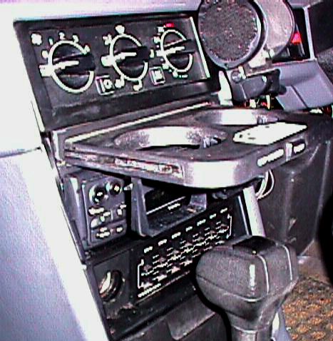
Installing a Ford Taurus Cupholder Above the Radio. [Tip from ] I've sucessfully mounted a 1/2 DIN-sized cupholder in my 940 suitable for cups and some (but not all) small cans / bottles. This is similar to the cup/coinholder mounting in a 760 / 960 which has been previously posted. Source of the cupholder was a Ford Taurus. Caveat: if you can't use a chisel, hacksaw, dremel etc and convince yourself you know what to do - don't start. To do this:
- cut to remove the coinholder
- remove the console 1 1/2 DIN opening / rack
- remove 1/2 mm each side of the console opening (the small lip) to allow the headunit fascia to be recessed into the opening
- trim side of cupholder to allow it to be recessed
- assemble mounting cupholder first. The headunit mounting frame should locate and fix this in place. Screw the frame to the base of the opening / rack
All trimming is to the sides of components which are recessed and not visible. Other Kludges. [James McKinney] I found a PVC plumbing coupler at a hardware store that was 3" in diameter and 3" tall that I sawed in half to 1-1/2" tall. Not an easy task with a hacksaw, but there was a indication of a line on the outside that I could follow. Then I glued both pieces (cut side down)to the inside of the door of the glove box with PVC glue. There are two indentions stamped on the inside lid. You cannot center
the pieces over these indentions or the pieces will not allow the lid to
close. They must be moved back about 3/8" toward the inside of the glove box. Before gluing the pieces down, tape one down and make sure the lid will close when in that position. Use a piece of foam weatherproofing taped to the inside to hold smaller cans secure.
Coin Holder. [Tip from Will] Volvo makes a coin holder that fits directly into your ashtray. Part number is 9166785, should still be available from the dealer. Makes it easier to get coins out, but only holds a few coins.
Plastic Glue That Works. [Tip from Carl Krall] When I was looking at my smithereened handbrake cover I remembered that I'd bought some plastic cement called PowerPoxy Plastic Bonder. It comes in one of those syringes, which I hate because it never comes out evenly although it looks like it should. Anyway, my cover is now elbow-worthy again, although I did break the tiny joint that goes under the handbrake while putting it back. I sanded the joint and glued it again with a strip of metal (folded-over farmer's helper) behind it for morale, and did it while it was in place so the agony of installation didn't have to be repeated. The stuff really stinks, and you've got maybe 5 minutes to use it once you mix it, so be ready and make a small batch. It's set in about 15 minutes, but I wait a day before I unclamp it or move it. Buy it at Builder's Square, and likely Lowes and Home Depot. The info number on the package is 800.248.7699, answers 8-4, M-F.
Converting Incandescent Lamps to LEDs. [Procedure from Jon Belmont]. I've finally finished (after about 4 months) converting the interior lights of my C70 over to red LEDs. I know that this is the 700 series forum, but I was asked to do a write up when I finished the job so that it could go in the 700/900 faq. With that in mind, the write up below is more of a general overview without getting into the nitty gritty... it's a good heads up for some of the issues ANY car owner might face if undertaking a conversion like this.
Conversion of incandescent interior lights to LEDs. For the last few months, I've been going through the process of converting the interior lights of my '99 C70 coupe over to red LEDs. As I've been talking about this process on the brickboard and with friends, many people have asked me about some of the problems I've run into and about how it went in general. I decided to do a write up on everything I went though, starting with a primer on some of the differences between LEDs and incandescent lights, then covering how those differences affected my conversion.
First of all, LEDs usually operate in the 1.7 to 3.5 volt range (depending on color, make sure you check first!), and the incandescent bulbs in my Volvo run on a full 12 volts. They also draw substantially less amperage, so you can run several LEDs off of a circuit that was used for only one incandescent bulb. Next to consider is that incandescent bulbs illuminate in a 180-degree range. In other words, if you look at a bulb from the top, it puts out just as much light as it does out to the sides. LEDs don't work that way. they illuminate in a cone shaped pattern that varies in width from 10 to 75 degrees. Usually, the wide angle LEDs are not as bright as the narrow high intensity ones. There are a few other specs for LEDs that you must look at when you decide which ones to use. Luminous intensity, which is measured in millicads (mcd), shows how bright an LED is. Also, the actual color of an LED is indicated by its wavelength, measured in nanometers (nm). Make sure that you have the same wavelength for all of your different LEDs. There are many different shapes of LEDs like oval, cylindrical, square, and rectangular. The lenses are clear or colored, transparent or diffused. The LED shape and lens type usually correspond to the viewing angle. Certain "surface mount" LEDs have wide viewing angles and are fairly bright, but they are EXTREMELY small and difficult to mount. Finally, there are "direct replacement" LEDs that are designed to replace incandescent bulbs. They may have a built in resistor so that they can operate at 12 volts, and some even have the proper mounting base (like a flange or screw base) that allows them to "plug and play" in place of incandescents.
The easiest bulbs to replace were the ones in a "direct lighting" situation, where the LED faces directly at the item being illuminated or there is Lucite light piping to direct the light properly. The switches for the foglights, sunroof, windows, door locks, courtesy lamps, headlights, and seat heaters all had incandescent bulbs that mounted into plastic twist-in bases. These were the easiest to replace; I just had to unwrap the leads of the lamps to free them from the bases and replace them with 12 volt T-1 (3mm) LEDs. In a couple cases, I had to bend the LED 90 degrees to point at the back of the switch you're illuminating (remember what I said above about viewing angle. some of the bulbs were mounted perpendicular to the switch). In the radio, the LEDs were soldered to the circuit board but Lucite directed the light to the back of the faceplate. They were easy to desolder and replace with the same kind of 12 volt T-1 LEDs (once I dissected the radio, that is). I had to angle the LEDs that illuminated the radio display so that there were no bright and dim spots, but it was relatively simple. 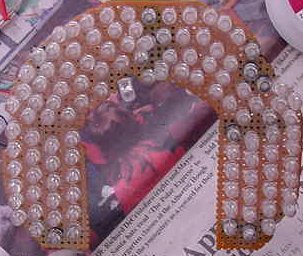
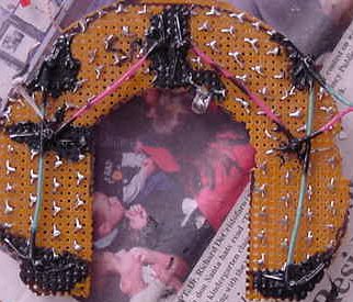
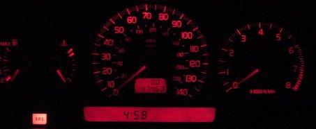
The items that were harder to convert were the climate control and the instrument cluster. The faceplates of those items were not directly lit by light bulbs, but were illuminated more indirectly using backlighting through the sides of the bulbs. Had I just swapped them out for LEDs, there would have been very bright and very dim spots. I had to use several more LEDs (a couple hundred) than there originally were light bulbs (seven!) to get the light distributed evenly. For the instrument cluster, I literally used hundreds of LEDs mounted to a blank breadboard and packed them in as close together as possible to ensure even light distribution. I also used a dremel to sand down the tops of the LEDs to try to diffuse the light (they were transparent) more evenly.
In situations where more than one LED is used to replace a light bulb, you can join them together in parallel and run them off of the connection for one light bulb. I also used lots of 2 volt LEDs and joined them together in series in groups of 6 (2 volts X 6 LEDs = 12 volts draw) so that I didn't need an in line resistor. Also keep in mind that some of the lights (such as the ones in the door and window switches) are already LEDs. Some of those look different (i.e. the anode and the cathode are reversed) and may already have a built in resistor so check that stuff with a multimeter to avoid messing something up. In summary, it was a LOT of work and entailed many obstacles I didn't anticipate. I ended up using about fifty of the 12 volt, T-1 LEDs for the switches and the radio and some of the climate control. I used about a dozen surface mount LEDs soldered in series to small wires to illuminate the rest of the climate control. Finally, I used almost 350 super bright LEDs wired together and mounted on breadboard to directly backlight the instrument panel, odometer, and trip computer. I got all my LEDs from eled.com. Great selection, quick shipping, and good prices for bulk discount. It was worth it and a learned a lot during the process, but make sure you do your homework before you get into it! I was able to finish the job as a result of sheer stubbornness more than anything else. You can see from the pictures some of what I went through.
[Tips from Jay Dymond] To assist in cold weather starts, you can install a block coolant heater or an inline hose heater, along with a battery blanket. I highly recommend a battery blanket. They are cheap (about $20.00 Cdn) and really help sub-zero starts. If you want the block heater, installing a new NAPA block heater is not difficult. It goes in the rearmost frost plug on the exhaust side (passenger side), next to the engine coolant drain cock. It's a bear to reach unless you are working from under the car. The frost plugs are metal discs, roughly 2.5 inches in diameter (from memory)along each side of the block. There are 3 or 4 of them on each side. Only one is appropriate for the block heater, due to interior engine casting obstructions and the potential effectiveness of the heater. The frost plugs are often thought of as a design feature that the car manufacturer used to ensure a frozen block would pop these things out rather than cracking the block. In fact, they are simply casting points from the engine casting. If you are installing the block heater yourself, jack the car up; block it up with jack stands after removing the passenger side front wheel.
This makes it much easier to gain access to the area under the manifold and work under the car. Drain your coolant from the engine petcock (you will probably want new antifreeze anyway, if you are winterizing your car, right?). Attach a plastic hose to the petcock and use a bucket to catch all the coolant. Get it all, it's poisonous to little furry critters like my doggy. Take a hefty screw driver or pointy type drift and a good sized beater stick and commence to beat on the frost plug till it is driven out. DO NOT MARK UP, SCORE OR MUTILATE THE LIP (or surround) THAT THE PLUG SITS IN OR YOU WILL NOT GET THE FROST PLUG TO SEAL. It can take a while to get the plug out, but all of a sudden it will drop out. I had all but given out when it popped out onto the floor. You can also try to puncture the plug and pry it out, but again, be sure not to damage the surround. It helps if you have really cleaned the surround on the block, and lubricated the o-ring on the block heater. Clean up the lip of the hole with a rag, getting all dirt and grunge out of the way; you want a very clean seal. Insert the heater, with a bit of non-petroleum based lube on the rubber o-ring. I used dielectric grease and it seemed to work well. Dino-oil type grease is not a good thing on rubber. As I recall, the heater element winds up pointing up about 11:00 oclock, but I may be wrong on that. At any rate, you will find it only fits well one way.
Tighten the puppy up according to the instructions you get with the thing. As I remember, mine tightened with an Allen wrench. Don't be a gorilla and overtighten it; it is a brass assembly and as such distorts/strips easily. The block heater will seat itself as you tighten the center bolt. Tightening the center bolt pulls the heater into the recessed surround, just like a drywall reinforcement used to hang heavy pictures or objects in a home. I have never heard of one falling out, unless someone has made like a gorilla and overtightened it to the extent the bolt has broken. If that happens I can only presume that after a while the block heater would be pushed out by coolant pressure (what is it, 12 psi?). There is no need to overtighten things. Just tighten it up so the heater is snug and partially recessed in the surround, and test for leaks. Route your cord to the front of the car appropriately (away from hot items) and tie in position with plastic ties. Tighten up the petcock, refill the engine with 50/50 antifreeze/water, put rad cap on, and start the engine. Check for leaks. If all is well, shut 'er down, put the front wheel on, and remove from jack stands. If you plug the heater in now (you didn't try out the heater when it was not installed, did you?.. a bad thing), you should hear it hissing and burping after a few minutes of current. Start the car up again. After you have brought the car up to temp, shut it off and let it cool down again. Check your coolant level again and adjust accordingly. Another good idea is to smear some dielectric grease on the contacts of the block heater, as this area does eventually corrode if you are in salty country. The same principle of installation holds for all 4 cyl Volvo engines. Our 6304 in the 960 however uses a pricey bolt-on heater attached to the side of the block.