Engine repairs and maintenance
Engine: Mechanical PDF
Engine Mounts:
Changing Engine Mounts on 740/940
Changing Engine Mounts on 960/90
Spark Plugs:
Cylinder Head and Valves:
Intake and Exhaust Manifold Gasket Replacement.
Headgasket Failure: Diagnostics
Headgasket Replacement Tips: B230 Series
B23X Head Bolt Removal and Re-installation
Headgasket Replacement Tips: B234
Headgasket Replacement Tips: B6304
Head Refurbishing: B23X Series
Combustion Chamber Deposit Removal
Burnt Valves in 740GLE Head with Hydraulic Lifters
Cylinder Head Valve Train Oil Holes
Valve Adjustment on B230 Series
Valve Adjustment Technique if No Shim Kit At Hand
Valve Stem Tip Rubber Cushions
Valve Stem Oil Seal Replacement
Block, Crank and Pistons:
Failure of Crank Timing Sprocket
Connecting Rod Bearing Replacement
Other:
Replacement Engine Splash Shield
Flywheel Position on Re-installation
Engine Mounted in Support Stand
Engine Mounts:
How To Inspect Mounts. The mounts should keep the front of the engine oil pan off the rubber bumper on the frame cross member. There should be a gap of 3/8 to 1/2 inch there. The fan should also be centered in the shroud. If not, your mounts need replacing.
Changing Engine Mounts on 740/940
Buy the Correct Mounts.
Note that earlier 740s came with solid mounts shown at the right, especially on turbos and manual transmission cars. Later cars have the hydraulic mounts pictured below. Buy the correct mount. Highly recommended that you buy Volvo OEM or Febi Bilstein mounts (OEM quality), not some nameless Chinese knockoff.
Safety:
Make sure the engine, when you raise it, is safely and firmly supported.
Raising the Engine:
[Tip: Bill Aileo ] Some folks carefully jack up the engine from below the short distance necessary (after making sure at least one side of the old ones is not connected. I prefer to use a 2x6 cut to fit snuggly over the engine compartment on top of the strut mounting area. [See Dick Riess' lift design in Special Tools.] The 2x6 is positioned like a joist and a hole for a piece of threaded rod is drilled near the center to line up with the lifting hook on the front of the engine. Put a piece of threaded rod about 12-18" long in place through the hole. Figure out a way to attached one end of the rod to the lifting hook and slip a large washer and nut on the other end. Then simply tighten the nut to raise the engine. Replacing the mounts is then easy. 
[Another Tip:] Instead of raising the engine by using a board between the jack and oil pan , I cut an angle at the end of a 2x6 and raised the engine at the front of the oil pan. The angled part of the 2x6 was pressed against the oil pan bolts at the front of the engine, the other end was square against the floor jack. I didn't want to risk damaging the oil pan. I also had to use a small hydraulic jack to help the engine raise straight. It worked fine and with new mounts my brick is running smoother now than it has in 10 years.
How to Change the Mounts:
[Procedures from Christopher Ascoli/Joshua Block/Editor] Raise the front of the car on jackstands or ramps and remove the belly pan for better access to some of the bolts. Before you jack up the engine, unscrew the top bolt on each motor mount. Lift the engine to remove the mounts AND SAFELY SUPPORT IT. You will not be able to reach from above all of the bolts which tie down the mounting bracket (that the motor mount sits on ) to the car's frame. Chilton's made it sound like all you had to do was unbolt the top and bottom of the mount and yank it out: not as easy as that! If needed, remove the bracket with the right mount because the bottom nut on right side mount is completely inaccessible with the bracket attached to the crossarm. I also took the left bracket off because of clearance. Some of these bolts are easier to access from below. If the mounts are OEM the nuts will be on rather tight.
Detailed Instructions: Driver's Side
- Remove the top nut on the mount. If this is seized (as it often is), use a u-joint, a few extensions, a big breaker bar, and a six-point socket to get your hands and knuckles up above the engine and then pull on it. It will come off, as long as you haven't rounded the corners from letting your wrench slip off the nut. In bad cases, unbolt the mount bracket from the block and from the crossmember to remove the assembly, mount it in a vise and get the breaker bar or air wrench on it.
- Raise the engine (the bracket that sits on the mount does not have to be raised all the way so it clears the top of the bolt; you will remove the entire lower bracket with the mount so you have some play)
- You can reach 2 of the 3 bolts of the bracket that the mount sits on, the last you'll have to get at from underneath the car
- Once all 3 bolts have been removed, lift the mount out with the bottom bracket still attached and you'll have access to the bottom nut that connects the mount to the bottom bracket.
- If you find that there still isn't enough room to remove the mount, you can remove the engine top mount bracket (or remove 2 of the 3 bolts and swing it out of the way) and then extract the mount.
- Attach the new mount to the bracket using anti-seize compound on the bolts. Install the bracket and bolt it in.
- Let the engine down making sure it sits on the mount correctly. DO NOT ATTACH THE TOP NUT UNTIL YOU HAVE BOTH MOUNTS INSTALLED!
Passenger Side
- Same as the driver's except you don't want to mess with the upper bracket. It connects WAY too many things to be screwing around with it. I didn't have to touch the top bracket at all. This side was definitely easier. If you're struggling with access to the passenger side, removing the pre-heater hose (non-turbo car) and perhaps the pre-heat manifold shield makes things easier. You may have to reach 2 out of the 3 bolts from underneath on this side. The job is not technologically challenging, but depending on when the mounts were last changed, you could be in for some blood and sweat. Just be careful not to strip the lower bracket bolts when removing (for obvious reasons), and some anti-seize compound on them when they go back in could make the next mount change a lot easier on you or the following owner. Good luck!
- Put the top nuts on both mounts. Make sure everything is tightly attached.
Other Ideas to Help the Work:
[Tip from Don Foster] When I do mounts, I offset the jack to favor the right side, and do the right mount. Then offset it to favor the left side, and do the left mount. In this way you avoid tugging on a good mount as you lift the motor. As you lower the engine onto the new mounts, you may need to persuade the stud into the bracket. Because of its angle, it doesn't naturally engage with the hole.
[Tip from David Steffy] You don't say whether you have a turbo. Our '88 is, so the left mount was easy and the right was a very tight spot. I took the brackets off with the mount in both cases, but didn't really need to for the left mount--just take off the upper nut and jack away. On the right one, I had to move the oil lines to get access to the bolts. Messy on my old gunky engine, a bit slow, but not a bad job overall. Without the turbo it's probably a lot better.
[Accessing the Mounting Nuts: Dick Riess] In my experience it is necessary to take off the belly pan to get at those front nuts on the drivers side. You also will have better access to the bolts, but a universal joint on your socket will help. I have had to attack from the front of the mount by the power steering rack and also from the rear. On the pass side, for me it helps to take off the oil filter to get at things and you may as well take off top and bottom mount brackets. Believe one of the bottom is bolted through the crossmember and you have to unbold from under the car. Jacking up your engine a little at a time helps access. When reassembling, tighten the mount to the bottom bracket, but leave the top loose so you can move it around for alignment to the block.
Preventive Maintenance Tips:
[Tip from Ed Kucinski] Just a reminder, when changing oil, keep the oil off the rubber motor mounts. Especially when changing the oil filter, some tends to get down there. Wipe it clean. Its the oil that deteriorates the rubber and speeds failure.
General Vibration Diagnosis:
See this interesting site for tips on diagnosis of internal engine vibrations:
http://www.vibratesoftware.com/html_help/html/Diagnosis/Engine_Speed_Related.htm
Changing Engine Mounts on 960/90 Series Vehicles. [Procedure by Walt Posluszny]
- Lift vehicle and set on jack stands.
- Remove the belly pan
- NOTE : The motor mount actually consists of two pieces, the rubberized mount itself and the metal bracket it is attached to. However, it is removed and installed as a single unit.
Passenger side (straightforward and fairly easy):
Removal:
FROM THE TOP
- Remove top nut (15mm)
- Remove rear most nut on the bracket (13mm)
FROM THE BOTTOM:
- Remove front inboard nut (13mm) on the bracket with a box or open end wrench.
- Remove bottom mounted bolt from the bottom of the bracket thru the chassis. This bolt is 12mm for some reason, and you will need to move the steering arm boot to get a socket on this bolt from below the bracket/chassis.
- Once all three nuts and the one bolt is out, carefully jack up the engine and chock tthe engine with wood blocks for safety (you don't want the engine to come down on your hand when you're taking out or putting in the mount).
- The mount will now come out to the front
- Remove the mount from the bracket by removing the one nut at the bottom of the mount (15mm IIRC)
Installation:
- Install new mount on old bracket
- REVERSE above removal procedure torquing the top (15mm) bolt to 37 ft./lbs. (there were no specs to be found for the other nuts/bolts).
Driver's side (a bit more challenging)
The procedure for removing the Driver's side is the same as the Passengers' side except for the following:
Removal:
I couldn't even see the mount from above so I decided to remove the following items to make the R&R even possible
FROM THE TOP
- I removed the aluminized cardboard hot air tube from the air box to the manifold. This facilitated now seeing the top bolt (15mm). I was able to use a very long extension to get to it from the top now.
- To get the above hot air tube out I actually removed the top of the air box to make life a little easier and to give me more room to maneuver
FROM THE BOTTOM
- I was unable to get a socket on the rear bracket nut (13mm). The metal power steering line was in the way. So from under the vehicle, from behind the front tire I reached in and kept bending the tube rearwards until there was enough clearance to get a 13mm socket on the nut from above. Once I accomplished this, I was able to get the nut off from above with a long extension and a wobble socket or you can use a universal joint because you can't get to it at the perfect 90 degree angl
- You have to also remove the oil filter. This will make it easier to get the inboard 13mm nut off the bracket, and give you room to pull the mount out from the front. Also don't forget to remove that 12mm bolt from below the bracket /chassis.
- You should now have all the nuts/bolts off, the engine safely jacked up and chocked, and the motor mount out from the front.
Installation:
- Install new mount on old bracket
- REVERSE the above removal procedure.
- Note : You can get the aluminized cardboard hot air tube back on the manifold from underneath the car from behind the front wheel. You can get your hand in there easily and install the tube and then go back on top and install the other end on the air box. You can also put the same oil filter back on if you recently changed the oil. I only lost about a cup of oil during this procedure.
Spark Plugs:
B2XX Series Engines and General Notes. The spark plug socket used to install plugs is sized 13/16 inch. A swiveling u-joint and three inch extension is also needed. To remove, see this video from John Goss: http://mazda626.net/topic/40729-dont-strip-or-break-it/ . In short, loosen about 1/8 turn, reinstall plug wires, start and rev the engine once, then shutdown and remove the plugs. This breaks carbon off internal threads. Stuck plug? Loosen slightly, then tighten slightly, and loosen more. To reinstall, see below.
If A Plug Is Stuck in the Head and Won't Come Out: [Steve McChesney] Use penetrating oil. [Brickboard penetrating oil preferences: PB Blaster, Kroil, Liquid Wrench, in order of effectiveness.] Soak the area, and run the engine. Let the engine cool off, and soak it again before you go to bed at night. Do this again and again and again. 30 or 40 times over the next few weeks would not be excessive. No need to have the stuff dripping all over, just use a little bit at a time. It's likely that the temperature cycling and vibration of the engine, with gradual penetration of the oil, will loosen the corrosion of the threads. The stuff is magic, but only if you have plenty of faith and patience.
[Don Foster] Use heat. I recently changed plugs on daughter's VW. One plug was dead tight, and when it finally broke free I was sure the aluminum threads were coming with it. Kroil didn't help. I first ran the engine for 15-20 minutes to get it good 'n hot -- aluminum expands at twice the rate of iron. The resistant plug backed right out without damaging the aluminum.
[HTH] Use both heat and penetrants. Soak liberally with KROIL, PB Blaster, or your favorite serious penetrant (don't even think about Liquid Wrench). Start engine, run about 3-5 minutes. CAREFULLY check the temp by putting your hand on the exhaust manifold to feel the heat. You want to stop the engine just as the head is warming up. Hopefully, if you get it just right, the head will have warmed up but the plug will not be at normal operating temp and the hole will be a little bigger than the plug. At least that's what I theorized and it worked for me.
If the plug was cross-threaded: you have a different problem entirely. See Spark Plug Hole Re-Threading. The head will need repair. Typically this mandates removal, but I have had good luck with high mileage cars by going ahead and using an impact wrench, starting off at a low ait pressure, and working upward as necessary. Again, liberal penetrating oil is a help. If you are commited, the ceramic insulator can be broken off the plug for better access. Once the plug is out, setting the offending cylinder piston to BDC and filling the cylinder with a foamy shaving cream will catch all the chips made when you helicoil -- or possibly only re-tap if the threads are not too bad. Crank the piston back to TDC slowly with a good shop vacuum covering the spark plug hole.
If you crack the insulator during removal: use some compressed air to blow out any ceramic chips so they do not fall into the cylinder after the plug comes out.
If the shell remains in the head: [Seamus Higgins] One plug was snapped off inside my cylinder head: the hex head, ceramic insulator, and the center electrode all came out with my plug socket, leaving just the threaded sleeve with the outer electrode still screwed in. While the plugs were only a couple years old, it was frozen solid. Even when using an extractor on the cold plug, it was impossible to remove. Here is what worked: buy a Hanson size-5 screw extractor, known colloquially as an ez-out. It's basically a tapered, reverse-threaded drill bit. [Editor's Note] Using an actual left-handed drill bit might make more sense as the spiral screw extractors ("Ee-zi Out") have a nasty tendency to snap off in the worst spots.]Soak the offending plug in PBlaster penetrating oil for several days. Start the engine and let it warm up: it will make a lot of noise and vibration and you will have gasoline fumes all over. Turn it off and give it a shot of penetrating oil. Now spray the hole for several seconds with freezing spray, which you can get at Radio Shack for around $8. It's used for testing circuit boards. Temperature shock of the different metals (aluminum head/steel spark plug) to break the corrosive bond is the theory here. Give it another good, soaking shot of oil. Put the ez-out back in with the extention and try to actually turn it out with the wrench. I had to repeat this heating/freezing/tapping cycle three times before it finally gave. Once it broke free it was a real bear, but it got progressively easier to turn as it came out.
Torque specs: Volvo says about 9 ft-lbs on the six and 18-ft-lbs on the four cyclinder engine. (700 series). Reduce torque about 40% if you used antiseize.
Using Anti-Seize to Prevent This:[Paul Grimshaw] I suspect that jammed spark plugs would be a much more rare event if folks used a bit of anti-seize compound [see Spark Plug Installation below], started the plugs by hand (socket & extension but no ratchet handle), and used a torque wrench to tighten the plugs to specification.Strangely enough though, factory torque recommendations are based on a dry fit (ie. no lubricant or anti-seize)??!*! (See below for torque recommendations. )Should one use some type of lube on the thread, you must back off about forty percent in pound-feet of torque to avoid stressing the thread in the cylinder head.
Analyzing Spark Plugs for Combustion Conditions. [Erling Brox] To "read" a spark plug's appearance, see the NGK website: http://www.ngksparkplugs.com/techinfo/ and look in the spark plug FAQ section for photos of various pluts
B6304 Series Engines. To remove the covers for the plugs, you will need a T-30 Torx for the cover screws, 10mm for the coil retainer screws, and a 5/8" plug socket. Remember the coils fire sequentially so don't mix up the wires.
Spark Plug Hole Re-Threading.Heads with dirty or damaged spark plug threads can be cleaned up with a thread chaser readily available at auto supply stores. Smear grease on the chaser. Carefully thread the chaser in and out of the head. The chaser will clean the threads and the grease will capture any metal bits or carbon in the vertical grooves.
[Inquiry:] I finally changed plugs in my aluminum-head B230F to find that my number two plug was somehow cross-threaded by a previous mechanic ( the plug was tough to remove, and the new plug tough to install.) Using a plug hole thread chaser did not solve the problem. Any solutions?
[Response:] The best repair is to use a product called Time-Sert. This is an insert that can be installed without removing the head and also is a quality, permanent repair. Check with one of your local foreign repair facilities, they most likely will have heard of the product and can turn you onto where to get it. You will also have to have the kit of tools to install the sleeve. Kit consists of drill bit to presize the hole, a countersink flycutter, step tap to create the threads for the sleeve and a roll tap to install the sleeve. The cost of the kit may exceed the justification to repair just 4 holes, so you might just have someone do them for you.
[Tip from Bob Dietz] Time-Serts are by far the best choice for thread repair. It's second oversize with respect to a heli-coil, a solid insert and has proved to be very reliable in the several I've installed over the years. They don't leak and don't come out.
[Rob Bareiss] A company called KD Tools sells a tap and insert kit you can use in the car. You should not need to remove the head. You will want to coat the tap with grease so it picks up its own chips as it cuts. The inserts look like little top hats- the brim is the stop when threading the insert in. They aren't like Helicoils, which are wound wire- these are machined solid inserts. Really good permanent job when complete. The tap is shaped jsut like a bolt- you drive it with a 13/16 socket. It's quite low-profile and should be able to be repaired with the head on the engine. Starting the tap at the proper angle is important of course, but it should be quite possible to repair this without major surgery. [Editor:] IPD sells a re-threading kit with the KD tool and thread inserts from Loctite.
Hints for Sparkplug Hole Re-threading. [Tips from Larry:] Here are a couple of things to watch out for:
- When you tap in the new threads, you'll want to catch as many of the metal shavings as possible by completely packing the tap with grease. Scrape the shavings off the tap several times and re-pack with grease each time.
- Blow out the cylinder with compressed air. If you don't have a compressor, buy a can of dust off from a photography store--it's used to blow dust off of negatives. It's important to have #4 at the top of it's compression stroke--both valves will be closed, so you're less likely to get metal shavings into the intake or exhaust manifold.
- Clean the new threads VERY THOROUGHLY with carb cleaner (toluene) and starting fluid (ether). The carb cleaner will dissolve the grease and the starting fluid will wash away the carb cleaner and evaporate completely. If the threads aren't clean, the cement for the heli-coil insert won't adhere.
Spark Plug Installation. Tips and Cautions from spark plug and car manufacturers.
Installation
[From ACDelco] Use the following four steps to properly install AC Spark Plugs:
- Make sure that cylinder head threads and spark plug threads are clean. If necessary, use a Thread Chaser and Seat Cleaning Tool.
- Make sure that the spark plug gasket seat is clean, then thread the gasket to fit flush against the gasket seat. Tapered seat spark plugs do not require gaskets.
- Use an AC Gap Guide to make sure new spark plugs have the correct gap setting.
- Avoid leaving fingerprints or grease on the plug ceramic shell to prevent flashovers and carbon tracks.
Gap: Volvo B230F/T and B234: 0.028"-0.032" or 0.7-0.8mm
Volvo B280: 0.024"-0.028" or 0.6-0.7mm
Screw the spark plugs finger-tight into the cylinder head by inserting the plug head into a clean rubber hose. One easy way to prevent cross-threading is to insert the plug and first rotate it backwards (counterclockwise) with your fingers until you feel the thread drop in (it feels like a "click" or a bump on the threads), then rotate forward to engage the threads. Use a torque wrench to tighten spark plugs following manufacturer's recommendations. It is most important that spark plugs be seated properly for correct heat dissipation properties. Seat the spark plug too firmly and the shell could be stretched, allowing combustion blowby to pass through the plug. It will be difficult to remove a spark plug in this condition from the engine. Seat the spark plug too loosely and it will overheat.
Torque Settings (use a torque wrench!):
- B230F/T and B234 4-Cylinder Engines: 18 +/-3 ft-lb or 25+/-5 Nm unlubricated torque per manual
- Volvo B280 V-6 Engine: 9 +/-1.5 ft-lb or 12 +/- 2Nm unlubricated torque
- B62XX/6304 Six-Cylinder Inline Engine: 18 ft-lb or 25 Nm "unlubricated" torque
Coat the inside of the plug wire boots with silicone dielectric paste to prevent them from adhering to the plug. Make sure the plug cap is tightly screwed down, then push the wire boot on until it "clicks". The wire installation sequence is the same as the firing order
Tightening, Torque and Anti-Seize Compounds:
[From AC Delco] Do not use any type of anti-seize compound on spark plug threads. Doing this will decrease the amount of friction between the threads. The result of the lowered friction is that when the spark plug is torqued to the proper specification, the spark plug is turned too far into the cylinder head. This increases the likelihood of pulling or stripping the threads in the cylinder head. Over-tightening of a spark plug can cause stretching of the spark plug shell and could allow blowby to pass through the gasket seal between the shell and insulator. Over-tightening also results in extremely difficult removal.
[From NGK] Torque is one of the most critical aspects of spark plug installation. Torque directly affects the spark plugs' ability to transfer heat out of the combustion chamber. A spark plug that is under-torqued will not be fully seated on the cylinder head, hence heat transfer will be slowed. This will tend to elevate combustion chamber temperatures to unsafe levels, and pre-ignition and detonation will usually follow. Serious engine damage is not far behind. An over-torqued spark plug can suffer from severe stress to the Metal Shell which in turn can distort the spark plug's inner gas seals or even cause a hairline fracture to the spark plug's insulator...in either case, heat transfer can again be slowed and the above mentioned conditions can occur. The spark plug holes must always be cleaned prior to installation, otherwise you may be torquing against dirt or debris and the spark plug may actually end up under-torqued, even though your torque wrench says otherwise. Of course, you should only install spark plugs in a cool engine, because metal expands when it's hot and installation may prove difficult. [From Denso] If threads are lubricated, the torque value should be reduced by approximately 1/2 to avoid over-tightening. [Editor] If you have no torque wrench, use a 1/4 inch socket drive which is short enough to limit the potential for overtightening.
[Tip from Underhood Service Magazine] One vehicle manufacturer warns against using antiseize because antiseize acts like a lubricant and may allow the plugs to be overtightened, which can damage the threads. If you do use antiseize on the threads, their advice is to reduce the tightening torque on the plugs 40%.
[Tip from Autolite] We do not recommend the use of any anti seize products for installing spark plugs. Antiseize compoundsare typically composed of metallic, electrically conductive ingredients. If antiseize compounds come in contact with the core nose of the plugs, it can lead to a misfire condition. Antiseize compounds can also have a torque multiplying effect when installing plugs. This can lead to thread distortion and thread galling resulting in cylinder head damage. Autolite spark plugs are nickel plated to resist the effects of corrosion and seizing. However, plug seizure is aggravated further when steel plugs are installed into aluminum cylinder heads for a long period of time. You may want to consider the periodic inspection of the plugs to reduce the likelihood of plug seizure during extended plug service intervals.
If You Do Not Have A Torque Wrench At Hand: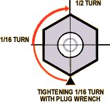

Always use a torque wrench to install spark plugs. However, if you do not have one at hand, you can use the following technique as a rough approximation [courtesy Denso]:
- First install sparkplug finger tight
- Then tighten another one-half turn using a wrench and spark plug socket
Caution on Spark Plug Number Four. [Tip from Rob Bareiss] I can't tell you how many people have screwed up the #4 plug. It seems to be difficult for some people to grasp the concept that since the plug came out at an angle, it needs to go back in at an angle. Too many of these have been crossthreaded.
What Happens When Plugs are Installed Incorrectly? [ImportCar Magazine, Sep 09] If the spark plug is over-torqued into an aluminum head, the aluminum
threads begin to “roll over,” causing a high degree of friction when the spark plugs are removed. In worst-case  scenarios, the threads actually separate or strip from the cylinder head casting and may require removal of the cylinder head to repair. In other cases, over-torquing a spark plug can distort and break the seal between the metal shell and porcelain insulator, which causes combustion gases to leak into the spark plug boot and blow it off the spark plug. If a spark plug boot keeps blowing off, suspect a seal leak caused by an over-torqued spark plug.
If the spark plug is under-torqued, combustion gases begin to leak past the tapered seat or metal gasket. This leakage causes carbon to form around the threads that, in turn, causes the spark plug to seize to the cylinder head. A properly torqued spark plug will show a bright register mark on the tapered seat or the gasket will show compression.
All of the above are good reasons to take a little extra time to properly torque the new spark plug.
Cylinder Head and Valves:
Top Dead Center. How do I locate "top dead center (TDC)" on my B230 engine? [John Sullivan] Some tips on locating engine position:
- When the notch/slot in the crank washer is aligned with the vertical mark on the block, the #1 piston is at TDC
- When the cam gear's mark is aligned with the mark on the timing belt back cover (about 11 o'clock), both valves for the #1 cylinder are fully closed, and...
- When the intermediate shaft gear's mark is aligned with the mark on the timing belt back cover (about 3 o'clock), the distributor's rotor is pointed at the #1 cylinder ignition wire contact in the distributor cap--and that rotor is also aligned with the mark on the distributor's base.
Intake and Exhaust Manifold Gasket Replacement.
Exhaust Manifold Gaskets. See the FAQ section for instructions on diagnosing and replacing exhaust manifold gaskets and safely removing the manifold nuts.
Intake Manifold Gasket.
Gasket Quality. [Editor] OEM is always the best choice. Elring works fine. One anecdotal report of early failure of a properly torqued Victor Reinz gasket was made at Brickboard.
B23X Engines. Disconnect the battery ground. Clean off the area around the gasket as best you can using spray brake cleaner. Remove all the manifold nuts. I find it helps to remove the fuel rail fixing bolts and pull it out of the way to better access the manifold nuts. Remove the pulley wheel bracket and the cable mount bracket or disconnect the throttle and transmission cables at the pulley wheel (take a photo or write down how they are routed) so you don't bend them while pulling back on the manifold. There will also be a couple of hoses, the flame trap, the air tube, an EGR tube into the top of the manifold (if so equipped) and a bracket beneath that have to be loosened or removed, but you'll see what is necessary as you try to pull the manifold away from the head. Pull it back just enough to clear the studs to replace the gasket. Be careful and don't tear the new gasket while inserting it on the studs. The surfaces should be clean and the old gasket was installed dry, so you do not normally need to scrape the area. Do not use any sealer or RTV. Retorque to 15 ft-lbs (20 Nm) for a B230 F/T, B234 or B6304 engine; to 7-11 ft lbs (10-15 Nm) for a B280F.
Intake Manifold Removal Tips. [Editor] Use narrow pliers to remove spring Corbin clamps from hoses but be careful not to lose them when you pull the hose off. Don't pull hoses off the air tube so hard you crack the plastic fittings on the tube. Now is a great time to clean the IAC valve and the throttle body and to consider replacing vacuum hoses that may be cracked or brittle. When you reinstall the manifold, make sure small tubes, hoses etc. are not caught up under the manifold when it is placed into position. When retorquing, the inaccessible nuts will have to be done by guesswork using a combination wrench. If you need a new EGR gasket, the p/n is 1378488 or use high temperature sensor safe RTV.
B6304 Engines. [Doug Young] To my amazement replacing my 960's intake manifold gasket wasn't as difficult as I had expected! I removed all the air intake tubing to the throttle body, then the throttle linkage assemblies along with the fuel rail and injectors. You may want to spray some non-silicone-based lubricant around the rubber couplings for the intake plenum and manifold so they'll slip out easier when loosened. At first I was concerned about the metal clamps that secure these rubber couplings. I decided that replacing them with plastic tie-straps would work just as well. You will need a universal jointl for your ratchet to get to some of the bolts. Be very careful removing them because those bolts love to fall and disappear into the bowels of hell. I grabbed hold of the plenum then pulled and wiggled it away from the manifold.When I pulled the manifold off, I found the intake gasket broken in about 10 separate pieces. The new gasket was around $16. I put everything back together and erased all stored codes. Turned the key and it made the sweetest sound without any stumble at all.
Vacuum Leak Diagnosis. See the FAQ section on diagnosing vacuum leaks in the intake system.
Headgasket Failure: Diagnostics
Basics of Headgasket Failure:
[Tip from Import Car Magazine, Oct 2001, Gary Goms] When diagnosing a leaking head gasket, it's important to remember that bi-metal engines with cast-iron blocks and aluminum cylinder heads will eventually wear out the head gasket due to the different expansion coefficients of cast iron and aluminum. Each time the engine goes through a warm-up cycle, the aluminum head slips a few thousandths of an inch across the head gasket. Although current head gasket technology drastically reduces gasket wear, head gasket replacement is still the most common major engine repair.
[Tip from Motor Service Magazine, Feb 2002, Greg McConiga] Two major causes of head gasket failure are overheating and detonation. Don't forget to check for the root cause of the failure, especially if it's a car with a history of problems. Cooling fan and water pump operation, radiator cap, thermostat, radiator flow, engine timing and EGR function are just a few of the things you need to check. [Fitz Fitzgerald] B230F head gaskets last longer than B230FT turbos: lower engine temperatures and pressures cause greater longevity. You can make yours last longer with a black low-pressure reservoir cap.
Headgasket Lifetime? [Editor] A brief, very unscientific survey of Brickboard users noted the following: B230 head gaskets still going strong at 303k (turbo), 300k, 203k, 220k. Failures were all due to cooling system failures and resulting overheating at: 150k, 200k.
Diagnosis of Headgasket Problems:
Symptoms of a blown head gasket include a continually increasing consumption of coolant, a milky accumulation found under the engine oil cap after extended engine runs at operating temperature, a very obvious thickening or sludging of the crankcase oil, gas bubbles exiting through the radiator cap,or inexplicable oil consumption. [John Ho] Another symptom can be increasing system pressure resulting in blown hoses, water valves, and coolant overflows. There are several diagnoses that can be done on the car that will nearly pinpoint the trouble spot and tell you if it is indeed a head gasket or something else.
- The first test that should be completed is a coolant system pressure test Test your system for leaks with 12 psi (85 kPa) for 1984-86 cars and 22 psi for 1987+ cars with B2XX engines. It should not show any noticeable pressure loss within 3 minutes.
- The second is a block test, also known as a combustion leak test, performed on the coolant in the radiator/expansion reservoir to determine if you have exhaust gases in your cooling system. A combustion test kit can be found on the web or at your local NAPA,Snap-On, or auto parts store. The part number is NAPA 700-1006 ($50) or Snap-On GDCT16 Combustion Leak Tester . The homemade version is in Special Tools. Exhaust gases in your cooling system can suggest a head gasket leak, a cracked block, or a warped head, etc. To do the test, add the blue detector fluid to the block-tester plastic container according to the directions, and place it onto the coolant reservoir. The squeeze bulb is squeezed repeatedly (Some block testers, have a tube that connects to a vacuum line instead of a squeeze bulb). Squeezing the bulb will draw air from the reservoir through the test fluid. Block tester fluid is normally blue. Exhaust gases in the cooling system will change the color of the fluid to yellow, indicating a combustion leak. If the fluid remains blue, exhaust gases were not present during the test. The vehicle should be started and at operating temperature before performing the test.
- The third, usually performed after a failing exhaust gas test, is a leak down test of each of the cylinders. This is similar in nature to a compression test but this actually will measure close to the exact location of compression leakage in the cylinder.
- A fourth test is a chemical analysis of the engine oil. Often, what might be construed to be a head gasket leak of engine oil could actually be seepage past a bad valve guide/piston ring, etc. In this scenario, a test of the motor oil will usually reveal inordinate amounts of combustion by product in the oil. Then again, if any of these are bad, the head gasket's gonna be removed anyhow.
Note: the above four tests are generally not shadetree mechanic things performed as the cost of the one time use equipment can be prohibitive. Well equipped shops can handle these types of tests. Sometimes it's worth it just to have a pro shop diagnose the problem, even if you are planning to do the r&r yourself.
Temp Gauge Acts Oddly: Leaking Headgasket? [Inquiry:] When I first get going, the temperature gauge will get into the middle, and stay there for few minutes. Next, it will rapidly shoot for the red zone. It will do this in seconds. The moment the red zone is touched, the gauge falls just as fast to the middle, where it will stay for duration of the trip. Next day, same situation. Should I be concerned, and replace the thermostat ?
[Response: Robert S.] You may have an air pocket during startup due to leaking head gasket or antifreeze leak (or combustion gases accumulating around the thermostat.) Try flushing cooling system to get junk out. Pressure test your cooling system to eliminate the possibility of the blown head gasket. When you first start your car leaking head gasket will introduce gas into the head cooling space. It will replace fluid from the area. The thermostat is closed so the gas has no place to go. The gas acts like an insulator so it will delay heat transfer to the thermostat. But other parts of the engine covered with the fluid blanket will heat the water up to the boiling point. Finally engine is hot enough to cause thermostat to open and let the gas go into the radiator. After the gas goes the overheated water and that's what causes your needle to rise on the gauge. Further operation is normal because thermostat is open and the gas goes to expansion tank as soon as it gets into the system. You need to repair the leak as soon as possible if that's the cause or you will end up with warped head due to spot overheating.
[Response 2: Art] I might add a note to suggest you squeeze the radiator hose early in the warm up cycle. If it is a bad exhaust leak it will have pressure long before the engine is warm.
Compression Test Procedures. [Tips from Motor Age Magazine, Apr 2002, by Glenn Hunt, adapted to Volvo B2XX]
When Should the Compression Be Checked?
By performing a compression test, internal engine malfunctions, such as bad valves, piston rings or excessive carbon buildup, can be detected before they cause irreparable damage. It benefits the owner to be aware of these problems so they can make an informed decision whether to invest in repairs or sell the vehicle.
How is the Engine Compression Checked?
The compression should be checked in any instance when an engine is running roughly or is lacking power. Engine compression on a gasoline engine can be tested in two ways. One method of testing involves the use of an electronic engine analyzer. But for the do-it-yourselfers, the easiest method is the manual compression test using a manual, handheld compression gauge. A screw-in gauge is generally more accurate than the gauge with the rubber seal.
- Run the engine until it is hot. A cold engine will not test correctly.
- Disable the ignition coil by disconnecting connection 1, ground, at the coil.
- Remove spark plugs for all cylinders being tested.
- Crank the engine continually for at least five to 10 full revolutions to obtain an accurate reading on the compression tester. The starter must be operating normally at around 4-5 revolutions per second or 250-300 rpm.
- Hold the throttle to full open position to ensure the engine gets adequate air intake.
- Insert the compression tester into one cylinder spark plug hole at a time. Specified minimum value for B2XX engines is 9 bar (130 psi)]. Normal compression is 9-11 bar (130-160psi).
- If all cylinder readings are within the Volvo B2XX specification [0.2 MPa or 28 psi] of each other, no further testing is required and compression is considered optimal.
- If any of them vary by more than this value, a problem may exist in one or more cylinders. Specialized testing equipment may be required to fully diagnose the problem.
- Spark plug re-tightening torque is 25 +/- 5Nm or 18 +/- 4 ft-lb.
What if the Compression is Too Low or Too High?
Consecutive low compression in all cylinders could mean that the problem of fuel washed cylinders exists. This means that the engine has had too much fuel introduced into it and all of the oil has been washed off the cylinder walls. The oil creates a sealing effect between the piston and ring assemblies and the cylinder walls of the engine block. Without this thin layer of oil, the engine compression would be allowed to escape into the crankcase. This is common with an engine that has a 'flooding' problem.
If the engine seems to run normally but is weak and puffs a small amount of bluish smoke, it could be an indicator of worn piston rings and cylinder walls. In either of these events, use a small oil can and squirt a little oil into each cylinder, then repeat the compression test. If the compression dramatically increases then you have found the problem(s). If the compression readings do not change, then it would indicate a timing problem between the camshaft(s) and the crankshaft of the engine. The timing chain or belt would need to be checked for proper timing.
If you find the compression reading is very low or zero in one cylinder, it is highly probable that internal engine damage exists such as:
- There is a 'blown' or weak sealing surface at the head to block mounting area, which basically means a bad head gasket (likeliest condition).
- A valve could be stuck or leaking.
- If the compression is low or zero on two adjacent cylinders, it might indicate excessive camshaft excessive wear or a broken camshaft (not likely with Volvos).
- The piston could have a broken connecting rod or a hole in it.
- There could be a broken valve spring or a bent push rod.
When the compression is found to be too high in one or more cylinders, this would be an indication of excessive carbon buildup in the engine. It can only be corrected by performing a chemical de-carbonizing process on the engine or by removing the cylinder head(s) and physically removing the carbon that is attached to the cylinder portion of the head(s) and the tops of the pistons.
Headgasket Replacement Tips: B230 Series.
Which Gasket Kit To Buy? [Tip from Rob Bareiss] For the B230F engine, your best bet is the Elring head gasket set from FCP Groton for around $55. This compares favorably with Volvo's own $120+ head gasket set. Even better is to replace the head gasket with Volvo OEM because of its high quality. If you have a turbo, buy the Volvo OEM exhaust manifold gasket set. I STRONGLY recommend getting the proper M8 copper washer-face exhaust manifold nuts from Volvo or a specialty parts shop. Use nickel-based Anti-Seize on those studs, too.
Basic Procedure for Headgasket Replacement. See the Headgasket Replacement file for a description of this procedure.
Procedural Tips and Ideas. [Mark Stites] Basic time estimates to repair are:
B230F: 8 hours; B230FT: 10 hours; B234F (16 valve):12 hours. Plan on additional time to send the head to a machine shop for refurbishing. See below for tool tips.[Chris Herbst] The head gasket repair job itself is NOT very hard. Drench the exhaust manifold nuts with PB Blaster penetrating oil. Get it at Wal Mart in the auto section, if you don't already have it. Squirt them for a week or so every day, before pulling the head. Clean the threads if necessary. If you believe them to be a disaster waiting to happen, then consider pulling the head WITH the exhaust manifold attached, and taking them off of the head when you have more control on the angle. Also if you break any you can fix them with the thing on a workbench rather than messing with drills in the engine bay. The intake manifold and associated things come right off easily if you have 1/4 inch drive 10, 12 & 13mm sockets. Disconnect any sensors necessary. If you are motivated, find a GOOD (ask shops who THEY use) machine shop and have the valves adjusted and the valve guides & seals changed if necessary. This will make for good performance when you're done. Usually around $250 for all machine services and adjustments. If you have to do machine work, take the sensors out of the head while it's being worked on. Make sure you have a good torque wrench for setting the head bolts. Clean it FASTIDIOUSLY before you mate the surfaces. Then put the new gasket in. IT is really an easy job to accomplish quickly, but the details depend on you. The only remaining thing is to line up the timing belt again (or also a good time to replace it if motivated).
[Rhys] Stuff oily rags into the cylinders and wadded up bits of paper towel into all the other holes in the block deck. Scrape the block surface with a sharp carbon scraper held at a shallow angle, using a vacuum cleaner to pick up debris. Wipe with lacquer thinner to reveal any missed spots. DON'T use an abrasive disk, pad or wire brush because you will leave debris or wires in the cylinders and if you don't get all of them out from space between the cylinder walls and the pistons it isn't good. Leave the pistons alone, but it you must clean them, do it very carefully, and hold a running shop vac in the other hand. Again, you do not want to introduce particles to the piston/cylinder wall area. Roll the engine over several times, oiling the bores, and wiping until they produce no further bits of carbon. Take the cylinder head to a machine shop and have them skim it to clean it up. Not only do you not have to worry about scraping and gouging the head to get the gasket off, the surface is now flat.
[Bram Smits] A paint scraper (with the sharp points rounded off - you definitely don't want to gouge the mating surface) or a dedicated gasket scraper tool will get you started. Then finish the job off with razor blades. I just did so, and with some work it'll clean up the block really well. Scrape, don't slice. Keep the angle low (30 degrees UP from FLAT is good to start). High angles make razor blades skip. Wipe both surfaces with a cloth soaked in lacquer thinner to remove remaining gasket and debris. [Bram Smits] Don't get any crud in the holes; stuff them with something you know you'll be able to retrieve, or just work carefully and direct the scrapings away from the holes as you go. Don't forget to clean out the bolt holes. Bolt torque specs are for oiled bolts; use plenty of oil or assembly grease when reassembling the head, and (you probably know this, but I'm surprised by how many people don't) the gaskets go on DRY! The torque specs for B230F/T are: first torque all in correct sequence to 15 ft-lbs, then torque all in sequence to 45 ft-lb, then all in sequence another 90 degrees.
[Chris W/Tom F.] Some tips from my recent headgasket replacement:
- One of the biggest time savers is a bunch of re-sealable plastic bags into which to throw all the hardware (nuts, bolts, etc.) along with a piece of paper noting whence they came.
- Pull the front RF wheel and get the car on jackstands in the front. Your back will thank you, and you'll need to spend a lot of time under the car.
- Be careful breaking loose the head bolts. Mine were very seized up and broke free with a SNAP. Use a six-point impact socket with a breaker bar and, if needed, a long cheater pipe on the end to remove these bolts. If needed, tap on the top of the socket with a ball peen hammer as you try to break free the bolt. Do not use an impact wrench since you have no control over the degree of loosening. Loosen each one successively only 1/4 turn at a time, in reverse of tightening order, so you do not warp the head on removal.
- The toughest part about removing the exhaust manifold was figuring out how to do it. This is what worked for me: (a) remove the three 13mm nuts from the manifold to downpipe flange (right behind the exhaust manifold) using six point sockets/wrenches, else you will round off a nut. (b) then unbolt the catalytic converter (three nuts). And (c) remove two exhaust pipe fastening points (one to the bellhousing, the other just in front of the cat). This allows you to slide the pipe out of the way. The manifold will still be attached to the block, with a T bracket just below the manifold. (d) Remove the oil filter to gain better access to this attaching nut (which faces the bottom of the car). Use some extension and socket combinations to remove this T bracket from the block and move the manifold away from the cylinder head. When reinstalling the manifold to the reconditioned head, first install the T-bracket onto the manifold, then as you slide the manifold toward the head, bolt it back to the block.
- Use liberal amounts of high-temperature nickel-based antiseize on all fasteners.
Removing Oil from Cooling System. See the FAQ notes on using detergent to remove engine oil from inside the cooling system.
Quick Head Gasket Procedure from Ted Yaffo:
I replaced a head gasket on a 93 940 turbo and did the entire job in 6 hours. The procedure was this:
- Drain coolant and oil
- Remove 8 intake nuts and using a piece of rope pull the intake manifold back towards the driver's fender as far as you can and tie it off. ...remove the air intake hose of the manifold for more flexibility
- Remove belts and upper timing cover, remove timing belt off the cam pulley and clamp it so it does not come off the lower two pulleys.
- Remove timing belt tensioner
- Use an impact gun to remove the cam pulley nut if you want to remove the cam oil seal; pull the rear timing cover toward the radiator and tie it off so it clears the two protruding head studs. The plastic cover will bend but not break if you're careful
- Remove the hoses which cross the valve cover from the turbo to the intake side
- Remove the large hoses which connect to the turbo
- Remove exhaust manifold nuts and throw away the protective covers bolted to the manifold; remove plug wires. Remove head bolts.
- Using a long pry bar, separate the exhaust manifold from the head by pushing the cylinder head back a bit towards the driver side. The manifold is bolted to the block underneath by a bracket, held to the manifold by a single nut virtually impossible to remove without removing the oil filter apparatus. This nut is left in place, fixing the manifold to the block so you will NOT have much room to pry it back but it will be enough to separate the head from the manifold.
- If you have pulled back the intake manifold enough you will have room to lift and remove intake side of the cylinder header with its protruding exhaust studs away from the exhaust manifold and up. [Ben Fingland] Removing the two rear exhaust manifold studs (or more) makes pulling the head off even easier.
- When you're ready to reinstall after all cleaning is done, place the gasket on the block. GET SOME HELP for the head installation: you will carefully move the head to the block and tilt in such a way the exhaust studs mate with the manifold holes. DO NOT FORGET TO INSTALL THE EXHAUST MANIFOLD GASKETS ON THE STUDS FIRST OR YOU'RE HOSED ("UT" on the gasket means facing "Out" toward the manifold). Once you know the studs will line up and slide into the manifold it is a matter of sliding and motivating the head to do as you want. Be gentle as you do not want to damage the gasket or the head. The only real problem will be, if you are rough, you can scrape the head surface on the two protruding locating pins on the exhaust manifold side on the block. Turbo Complications: [Brian Mee] We couldn't seem to make that last rotation to get the head flat on the block while still on the (loose) manifold. I loosened the 4 bolts holding the exhaust manifold to the turbo, two bolts from the manifold to the block, and one bolt underneath. That finally allowed the exhaust manifold to move about an inch which did the trick.
It not only can be done this way it is VASTLY faster and easier. By leaving the entire exhaust/turbo side integrated you save a huge amount of time and the risk of snapped bolts/nuts and major aggravation.
Tips from Victor Reinz Inc and Corteco:
- Never use a Scotchbrite abrasive pad to whiz off old gasket residue from a head or block. Abrasives can leave low spots on the surface that will prevent the head gasket from sealing. Use a gasket-removing compound and a scraper or soft wire brush on the block and a plastic scraper on the aluminum head. [Engine Builder Magazine, July 08] When cleaning engine gasket sealing surfaces, and/or cleaning engine components which are to be reused, surface conditioning discs (typically constructed of woven fiber or molded bristles) which contain abrasives, such as a high amount of aluminum oxide, are NOT recommended. The use of such surface conditioning disks dislodges aluminum oxide from the disc and metal particles, which can lead to premature engine bearing failure. In some cases, this failure occurs in as little as 1,000 miles or less after the repair has been made.
- If the surface finish on an aluminum engine head and cast iron block is too rough and digs into the gasket too deeply, it can literally tear the gasket apart over time. That's why surface finish is so important. For bimetal engines with composition gaskets, the recommended surface finish is 20 to 50 RA.
- Inspect all head bolts to make sure they are in perfect condition with clean, undamaged threads. Dirty or damaged threads can give false torque readings as well as decrease a bolt's clamping force by as much as 50%! Bolt threads should be wire brushed, then inspected. Replace any that are nicked, deformed or worn. Bolts should also be measured or compared to one another to check for stretch. Any bolt that's visibly longer than its companions should be replaced.
- Run a bottoming tap down each bolt hole in the block. The tops of the holes should be chamfered so the uppermost threads won't pull above the deck surface when the bolts are tightened. Clean all holes to remove any debris. Remove any fluid in the block bolts holes, otherwise hydraulic pressure will cancel any torque you apply if the fluid is higher than the lowest bolt thread point.
- If the head has been resurfaced, check bolt lengths to make sure they don't bottom out in blind holes. Make sure bolt lengths are correct for each hole location (some holes require longer or shorter bolts than others). Bolts should also be measured or compared to one another to check for stretch. Any bolt that's visibly longer than its companions should be replaced.
- While the head is off the engine, check the flatness of both the head and block. Use a high-quality machinist's straight edge and feeler gauges to check all critical areas - especially those between the cylinders.
- Lubricate bolt threads as well as the underside of the bolt head with 30 weight engine oil (not assembly lube or grease) when the engine is assembled. If the bolt shares a colant passage, use thread sealant. Use a calibrated torque wrench and carefully follow the tightening sequence in stages using a smooth, continuous pull.
Head Surface Warpage. [Scott Cook] Whenever you remove the B230 head, check it for warpage:
- Using a metal straight edge and feeler gauges, measure the short way across the head, between the cylinders and at each end. The maximum distortion specified in the Volvo manuals is 0.25mm (0.01"). Above this and you must machine the head (but see below).
- Measure diagonally across the length of the head. From the right rear to the left front and vice versa. Maximum distortion in this dimension is 0.5mm (0.02").
- If the distortion or warpage in the short dimension across head is 0.5mm (0.02") or more, or in the diagonal longer direction is 1mm (.04") or more, the head must be replaced, not machined and reused.
Head Bolt Removal and Re-installation.
B23X: Bolt Removal. [Inquiry]I tried removing the first head bolt in the star pattern order shown in my manual. I stopped because I was putting lots of torque on the bolt and it wouldn't budge. I didn't want to break it off. What should I do? [Response: John Sargent] You must use lots of force: they are quite hard to remove. I use either a 6 point 1/2" drive 14mm impact socket or a 6 point 3/8" drive deep impact 14mm socket with a breaker bar and 4-5 foot long cheater pipe to remove and intall the headbolts. You will break even a Snap-On 6 point 3/8" drive socket on this job. Don't use a 3/8" drive socket unless it is a black impact socket. Use the Volvo OEM or IPD crank pulley holder tool; the one from FCP Groton is crap: I've found it effectively fits neither of my b230 engines. See also Mechanical Tips.
B6304: Bolt Removal. [Ned Chilton] Bolts are tough to remove. Use a 14 mm deep well impact socket with 1/2 inch drive, an extension, a breaker bar and a 24" steel pipe for leverage on the breaker bar. You may have to slightly grind down (by about 1/32") the OD of the deep well socket so it will
fit down into each bolt hole on the head. As you apply torque, you can feel and hear each bolt “give” with a crack sound as each one first loosens. Then they appear to tighten back up as you try to move the threaded portion. Just keep at it even though it feels as though they may fail. One technique is to have someone tap the top of the breaker bar at the socket with a ball peen hammer as you apply torque to loosen the bolt. If they're gonna break (i.e., fail), they're
gonna break no matter how you do it. Ask me how I know. If they didn't
break on your initial loosening, you should be fine. Definitely use new
bolts to put it back together. Torque instructions are below.
Broken Headbolt? [Don Foster] If the broken bolt is under the surface, the block has to go to a machine shop for drilling and retapping. If 1/2" or so is sticking out of the block, you should be able to get a stud remover on it. Or you can try Vise-grips, but they usually chew things up. Use PB Blaster or Kroil, soak it several times a day for a week or more. (WD-40 and Liquid Wrench are totally worthless except as tar solvents.)
Bolt Re-Installation. [Tips from Engine Builder Magazine, Jan 02; edited for Volvo content]
- New Bolts? As fasteners are tightened in the engine, they stretch. Because of the elastic properties of steel, the fastener wants to return to its original length (tension). Load on the gasket surface is created by the elasticity of the fastener and this desire to return to the original length. Fastener threads deteriorate with use and also can become damaged by handling and cleaning, negatively affecting the ability of the fastener to deliver the desired load on the gasket. There's also the potential for fasteners to fatigue, to work-harden and to become at least partially yielded during normal engine operation. Volvo recommends not reusing headbolts more than five times, with the clear suggestion that it's OK to reuse them up to five times. Bolts used in recent engines since 1980 are not "torque to yield" and can be safely reused. If you reuse them, measure each bolt to make sure none has stretched to 55.5mm or above.] Head bolts used against aluminum often have a hardened washer to help distribute the load. Make sure the rounded or chamfered
 side of the washer is facing up. Tip: if you replace them, don't use cheap aftermarket bolts; buy the Volvo OEM quality fasteners.
 - Thread Hole Quality. Often neglected, but equally important as the fastener, is the condition of the threaded hole the fastener screws into. Thread chasers (different from taps: they do not remove much metal) should be employed to chase every head bolt hole. Clean out any coolant and oil in the thread recesses. In the traditional method of tightening fasteners, using a torque wrench and tightening to a specified point, thread friction accounts for about 45 percent of the tightening effort applied to the fastener. Rough threads in the block can increase that percentage, robbing effort that would have, under normal conditions, been used to stretch the fastener and load the gasket. [Randy Starkie] I have always power wire-brushed the bolts. I also always use solvent/degreaser in the headbolt holes. I have also used some lightweight wire brushes used in rifle or shotgun cleaning in conjunction with the solvent. I then surround the bolt hole with a rag and use compressed air to blow out the degreaser. I spray more degreaser in and blow it out again. Recently I made a cleaning device using an old headbolt with four flutes cut in it with a die grinder which I use before the degreaser and air routine. [Underhood Service Magazine, Jul 2004] Resurfacing a cylinder head decreases its overall height, so be sure to check bolt lengths to make sure they won't bottom out in blind holes. If a bolt bottoms out, it will apply little or no clamping force on the head, which may allow the gasket to leak. If a head has been milled and one or more head bolts may be dangerously close to bottoming out, the problem can be corrected by either using hardened steel washers under the bolts to raise them up, or by using a thicker head gasket.
- Thread Lubricant. The standard lubricant for threaded fasteners is 30-weight motor oil. Both the threads and underside of the head of the bolt should be lubricated because these are the two major friction sources. There are, however, a couple of exceptions to this general rule. One is for fasteners that screw into contact with the water jacket. Their threads should be coated with a thread sealer rather than 30-weight oil. Another case is when the fastener comes with lubricant or sealant pre-applied. The use of so called super lubricants (molybdenum-based assembly lubes, graphite, Teflon-based products and even beeswax can all be used to lubricate bolt threads and heads)can actually be detrimental, reducing the friction so much that the fastener is inadvertently yielded in the normal tightening process. The logic in this is if the bolt is stretched the desired amount using 30-weight oil as a lubricant, then using a lubricant that reduces friction more than 30-weight oil will result in more stretch at the same torque. This could potentially cause a fastener or a gasket failure. So use only 30-weight oil as the lubricant. For bolts threaded into blind holes, lightly lubricate the threads and underside.
- Washers. If any were installed, make sure they are positioned right side up (usually with their rounded or chamfered side up) and that there is no debris or burrs under the washers.
- Tool Accuracy. Your stakes are very high when you rely on tightening tools. A torque wrench that is off by 10 percent can be the difference between success and failure. Torque wrenches are still used for lots of conventional tightening jobs, and they need to be checked and calibrated. The old fashioned deflection beam style torque wrenches are the least expensive wrenches but also the most accurate in terms of holding calibration. Unfortunately, they are also the hardest to read because of the pointer and scale on the handle. Dial torque wrenches are easier to read, but are more expensive and apt to be damaged if dropped. Adjustable torque wrenches that can be preset to click or slip when a certain torque value is reached are the easiest to use, but are expensive and need to be recalibrated on a regular basis (every 100 engines or six months, depending on usage).Use an angle indicator on the end of the wrench when the specification calls for angle tightening.
- Proper technique when using a torque wrench: use socket extensions to clear obstructions so that you can swing the wrench through the entire arc in one continuous motion right to the appropriate torque value. If you need to reposition the wrench handle to clear an obstruction, do so in such a way that the last movement to the correct torque value will be continuous and not jerky.
- Follow the Manufacturer's Specs Closely.
- B230F. Tighten the oiled B230F four cylinder head bolts in stages (see your shop manual for the specific tightening pattern, bolt by bolt):
- 20 Nm, or 15 ft-lbs
- 60 Nm, or 45 ft-lb
- Angle tighten another 90 degrees using a "Torque to Angle" indicator on the wrench or some other angle indicator
- B234F. Tighten the oiled B230F four cylinder 16 valve head bolts in stages (see your shop manual for the specific tightening pattern, bolt by bolt):
- 20 Nm, or 15 ft-lbs
- 41 Nm, or 30 ft-lb
- Angle tighten another 115 degrees using a "Torque to Angle" indicator on the wrench or some other angle indicator
- B6304. Tighten the oiled B6304 six-cylinder head bolts in stages (see your shop manual for the specific tightening pattern, bolt by bolt):
- 20 Nm, or 15 ft-lbs
- 60 Nm, or 45 ft-lb
- Angle tighten another 130 degrees using a "Torque to Angle" indicator on the wrench or some other angle indicator.
- B230F. Tighten the oiled B230F four cylinder head bolts in stages (see your shop manual for the specific tightening pattern, bolt by bolt):
If a bolt is not coming up to normal torque or is not holding a reading, it means trouble. Either the bolt is stretching or the threads are pulling out of the block.
Headgasket Replacement Tips: B234 Series.
[Inquiry] My head gasket in my B234 needs replacement. I removed the top half of the front cam belt cover and the plug leads & black cover with oil filler cap on it.
Now I'm staring at what looks like the TWO piece head that I read about for the B234F 16V motor. How do I remove all this? [Jeffrey Saeger] First you must remove the intake and exhaust manifolds, the belts, fan, timing belt covers, timing belts etc. Easier if you pull the radiator, too. Then you remove the cams, then the hydraulic lifters (using a magnet, keeping them in order, and storing them upside down to keep oil within), and finally the cam carrier.
I do not use a cam hold down tool. I just loosen the cam bearing bolts as evenly as I can, trying to keep equal pressure on the cam.
Then the head.
You need some special anaerobic sealant to put the cam carrier on the head.
It's lots of work. I have used the Chiltons for guidance, it's the only thing out there if you do not have a Volvo Green Book. Online guides include Bill Garland's excellent B234 teardown website.
Headgasket Replacement Tips: B6304 Series.
[Tips from Patrick McGinnis/Tom Irwin] This job is not for the faint of heart or mechanically dysfunctional!! You should have the OEM green service manuals. You will need a 6 point 14 mm 1/2 " drive long socket, power bar and long cheater pipe! Those head bolts are on there! You need as well a good set of Torx allen wrenches, PB Blaster, light, mirror, electronic torque wrench, and patience.You will also need a way to align the camshafts when you re-install without the benefit of the Volvo special tools. I used the Corteco head gasket set & new bolts. You need all new head bolts since they are torque-to-yield and stretch on installation. You will also need to buy the gasket for the coolant pipe from Volvo along with the special gasket goo for between the cam cover and head.
- FOLLOW THE MANUAL INSTRUCTIONS & PUT THE GOO ON THE CAM COVER DURING RE-ASSEMBLY. Why? You fill up the oil passages and holes in the head if you don't which means you will be taking it all apart again. Ask me how I know!
- Align the camshaft timing marks & then put match marks on the gears & camshafts BEFORE you remove the gears or take off the cam cover. I use a small cold chisel that leaves a mark in the middle of the cam gear and cam.
- You must remove the cams.
- Number the lifters by cylinder & valve location before removing them from the head.
- A steam cleaner works perfectly to get all the old gasket material off the engine mating pieces, otherwise you will spend hours scraping.
- Chase the holes for the bolts with a thread tap.
- You should also try to borrow a head bolt angle installation guage. You need to turn the bolts 130 degrees after the final torque spec and you can't do it in 1 motion. TRUST ME! The gauge is essential to getting it right, you have no idea how much futzing is required to get the socket on the bolts, pull, re-adjust, pull, etc, you need some sort or angle indicator. Your back will hurt the next day. Extreme patience is needed to install the top of the cylinder head after all your head bolts have been torqued. [Paul Golden] Don't torque the bolts to the final factory spec: it is too tight and tends to crack the blocks. When I torque the bolts I start in the center and move outward. I like to coat the threads of the bolts with a white lithium base grease to prevent binding. The first torque is 25 foot pounds; the second torque is 45 foot pounds; the third torque is 45 degrees;the fourth torque is another 45 degrees; and the final torque is another 45 degrees. I use this torque sequence for all the 4, 5 and 6 cylinder aluminum engines.
- [Tom Irwin] The cam-locks are real nice to have. But the cam carrier squeeze tools (a pair of them) are a must-have in my book! Your only option is to sequentially torque each of the 48 cam carrier bolts, a tiny bit at a time. And those threads are so frigging fragile that I stripped 8 of them last time before I ever got near the torque value. Blow one of them and your engine will be puking oil very soon. The cam carrier press tools thread into the #2 and 5 spark plug holes. They have a thread starting knob to seat in the spark plug holes and then there are steel wings you turn to achieve the squeeze. You really must use these. there is no non-dealer option that I am aware of. I have heard of desperate individuals making their own crude copies, without the bearing plates.
- Bolt the thermostat housing to the head BEFORE mating it to the block. Access is very tight after it is installed.
- There is a whole buch of stuff bolted to the back of the head with about 2" of clearance to the firewall.
- The ungodly, unreachable bolt on the bottom of the intake manifold is best addressed with an S shaped or obstruction type 13mm wrench. Hold it palm up and wedge your hand between the harness and other crap next to the manifold while sliding the wrench to the left, finding the bolt, getting a grip, and loosening it 1/4 turn or so. Repeat as needed. Swear a bit. [Tom Irwin] Aafter my 5th time it is not too bad. If you can handle some slight contortions, you can do it. The key is to pull the hot air exchanger completely out and get a hand up in front of the rack and pinion.
Suggested Engine Removal. I suggest that you remove the engine and transmission as one unit. To take the engine and tranny out requires less than 2 hours. To remove the head in the car requires scraped knuckles and lots of expletives plus many more hours and more headaches. I will not do this job ever while the engine is in the car!
Removal of Cylinder Head. [Inquiry] I am trying to get the top half of the B6304 cylinder head off. I've removed the 46 bolts, the cam position sensor, the screw in the back on the connector bracket which is threaded into the top cyl head section, and the cover on the intake cam is loose. I think that all that is holding that top half down is the chemical gasket. The Volvo manual say to CAREFULLY tap upwards (with a copper mallet) on the top section & the camshafts to push it up. There aren't a lot of places to tap upwards. I am reluctant to try to chisel/pry the two halves apart for fear of damaging the sealing.
[Response: DanR] The first time I did this I had tremendous reservations with using a mallet. The Volvo green book I have came with new update stickers where the direction to hammer with a mallet was covered up and the new direction was to order the Volvo special tool which not only holds down the top to put in the bolts but also pulls it off and breaks that seal. I think too many mechanics were breaking the hammer points. I proceeded without the tool and used a soft mallet and a screw driver at the two or three spots where there is a little tab hanging over the outer edge of the head cover. These tabs have the guide pins in them. The glue is strong, but using a flat blade screw driver in those spots did the trick. Do not use any thing to pry on a sealing surface: these are machined to a very tight tolerance; a few scrapes and things will be leaking later.
Head Refurbishing: B23X Series. [Randy Starkie] My experience is that the heads on the Volvo red blocks seldom need
"rebuilt" in the strict sense of the word. "Freshening up" might better describe what I have done. I have never had to replace any valve guides in these heads and I have only replaced one valve. A quick count brings up a number of seven that I have gone through. Several of those were turbo heads of which one was cracked and needed to be replaced, but otherwise none have been terribly warped. I believe .004 is the tolerance for out of plane and most of them were out that much or a bit more so a clean up cut was called for.
If you have a valve spring compressor and a "power wire brush" you can probably do most of it yourself.
Check and record the valve clearances. Disassembly is easy enough and the bits can be placed in numbered ziploc bags to keep them ordered. Read the FAQ’s about cam removal. Be sure to remove the spring seat that is between the head and the valve spring so it does not get lost. A couple of dental picks are a great help for this, and be careful not to drop one and have it disappear into the galley; they can be extremely difficult to find and extract sometimes (BTDT). Either clean up the head yourself (carb cleaner) or have your selected machine shop do it for you. Have them check the head for plane and take a cut if needed. If you are not familiar with how much clearance you should "feel" in the guides you will want to take one along that represents the maximum wiggle between stem and guide and have them evaluate it.
Put on your safety glasses and use your power wire brush (bench grinder or die grinder attachment) to remove all the build up on the valves. Apply significant pressure to remove all surface build up.
In anticipation of the work you are doing you probably ordered a head gasket set. I always use Elring. I can’t remember if the set includes the hushers (rubber seals on the top of the stem) and stem seals but I am pretty sure that it does. This would have been a good time to order any valve shims you need to correct the clearances. You can use a micrometer on the shims of any valves out of tolerance and calculate the shim you need to put it right.
if the valve guides are out of spec, have the shop press out the old valve guides and install new . Use valve guides from Volvo or the OEM manufacturer. Do not let them talk you into "knurling" the existing valve guides. Knurling valve guides is a questionable practice. Inspect the valves for true and the seating lip. Rarely do these need replacement. Verify the valve spring health for strength, compression, and rebound. These can fail, yet only rarely. Inspect cam journals and the cam itself for true and damage and scoring.
When you get the head back you can lap in the valve/seats. It only takes lapping compound and the tool which has a suction cup end. Simply apply the compound, attach the cup to the valve and rapidly roll it back and forth between your palms while applying downward pressure. As your hands end up to low on the tool to continue pick the tool and attached valve up and redistribute the compound on the surfaces. You really can’t hand lap too much so spend some time at it. Clean up the valve and seat when you are done and examine them for evidence that the abrasive has contacted and knocked down the sheen of the surfaces all the way around. Rebag the valve when done. Remember you want all the components to be assembled with the ones that they were originally with. After all the valves have been lapped double clean to make sure no lapping compound remains on the head or valves. Make sure all areas of the head are clean of foreign material.
You are ready to assemble the head at this point. Start at one end with the appropriate bag of pieces. I oil the guides and put assembly grease on the stems. These heads only have guide seals on the intake valves. When installing intake valves I oil the seals and install the valves in a rotating fashion until the valve is seated. Replace the spring seat that goes between the spring and head. I always slip it onto a long skinny screwdriver and place the screwdriver into the guide- just some insurance they don’t get dropped into the galley. Install the springs and retainers and compress the assembly. Install the keepers. A bit of lithium grease on the keeper halves will insure that they will stay in place while you slowly decompress the springs.
Once the springs are in place go back and install the rubber seals (hushers). Give each assembly a couple of tablespoons of engine oil. Put assembly lube on the cam followers and their mating surfaces on the head, install them on the correct valve with the shim that you have determined will give you the correct clearance.
Install the cam after applying assembly grease, it is easy to install it now in the TDC position. Draw down the caps a little at a time as described in the FAQ’s (opposite procedure of removing the cam). Install the camshaft oil seal.
You may need to check valve clearances after some miles.
Combustion Chamber Deposit Removal. For Chemical Removal Techniques, see the FAQ link. Water Techniques. [Tip] My check engine light came on while at the Blue Ridge Parkway, so I take it to my friends shop and they determine the it's the O2 sensor, they run a further test which shows it's voltage regularly dropping well below the minimum, but this still doesn't prove anything. They reset the light and it stays out. But then, he takes a jar of water and using a section of vacuum hose connected to the vacuum port for the cruise control he quickly dips the hose in the water repeatedly while reving the engine, not very high, producing plenty of steam and a really small deposit of black on the ground under the exhaust pipe. Here is the technique:
- Engine should be fully warmed up.
- Connect an 18" vacuum hose from a vacuum port between the throttle and the manifold. I used the small vacuum nipple on the manifold where the flame trap connects to the inboard side of the intake manifold. I just pulled the small hose from the manifold and left it disconnected: reconnect when done.
- Take a jar (normal size mayo or spaghetti sauce jar) filled with water (this would be just under 3 cups)
- One hand holding throttle open so engine remains in the 3 to 4 thousand rpm range.
- Dipping hose in water over and over approximately once a second for about 1/2 (0.5) second or less, less often if engine slows significantly, engine will run rough so use throttle to maintain engine speed until all the water is gone which will take only a couple of minutes more or less.
- Repeat with the 16 oz can of Seafoam Carbon Cleaner or GM Top End Cleaner. NOT recommended: carburetor cleaner or Berryman's Chemtool.
- Let the engine stall before you run out of cleaner and let it sit for 15 minutes. Then restart and finish with the Seafoam.
- Remain alert and focused and just don't let the hose stay in the water/fluid for much more than half a second at a time and you should be safe. You know you are feeding in too much fluid if the engine speed drops significantly even though you are trying to maintain it with the throttle.
- Take the car out for a vigorous run at high rpms.
His technique was to dip the hose (with no orifice) in the liquid (only when the engine is running at a mid rev range) only for a second at the most, but over and over again not letting the engine slow significantly, using up all the fluid. Next using exact same method with an injector cleaner, Sea Foam Carbon Cleaner (SF16, UPC#: 1881200001) (or GM Top End Cleaner), this time producing plenty of smoke, both black and blue. She survived I thought to my self. Did not expect any difference in the car but I was wrong. This made a car that felt great feel much better, pulls stronger, revs smoother, louder exhaust.
Other Ideas. See the Notes in the Engine:Performance Section for more ideas and tips.
Burnt Valves in 740GLE Head with Hydraulic Lifters. [Problem Diagnosis by James Rothe] At about 90k miles, my 740 GLE started a recurring burnt valve problem. Three times (!) did I have valve(s) replaced before we found out what the problem was. I should add that throughout my ownership of the car it has burned oil -- slowly, so that you could not see blue smoke -- but as much as one quart per 1000 miles. The previous owner reports the same. The dealer said that was within normal limits.
What we finally found out was that early B234 engines, with their hydraulic valve lifters, had an infrequent manufacturing defect in which the holes for the valve guides were made ever-so-slightly oval. The problem, as it was reported to me, is that the hole in the head itself, into which the guides are pressed, was oval. It's an infrequent defect that reportedly occurs in both 740 and 850 heads with hydraulic lifters. That's a very different situation from having defective valve guides or seals.This is not exactly a perfect fit for a circular valve guide, so it allowed a small amount of oil to seep onto the valve. The speculation is that this burned onto the valve, caking up the valve with carbon deposits, and prevented the valve from properly seating. Without proper contact with the cylinder head, the valve could not transfer its heat to the head and it burned.
My mechanic, a family friend who works as a mechanic at a Volvo dealership very nearby Volvo's North American headquarters in Rockleigh NJ, found out that Volvo is aware of this problem in the 89 740 GLE and in other Volvo engines with hydraulic lifters, like the 850 series, but that the problem is not statistically significant enough to justify a [costly] recall campaign. Or so says Volvo Customer Relations.
We didn't find out about this manufacturing defect until after two top-end rebuilds, by which time the car had over 120,000 miles on it. Needless to say, Volvo declined my request for goodwill service. Part of their argument was that this problem usually shows up within the first 10,000 miles. My response was perhaps, but if it's been going through oil for all of it's life, and that condition stops after the valve guide hole is corrected, doesn't it make sense that this oil control problem at the valve guide would adversely affect the valve, just like your 'statistically insignificant' manufacturing defect is known to do? I also added that I was the first owner to do extensive hi-speed highway mileage with the car. The previous owner may have never got the head as hot as I do every day. It didn't matter.
They finally put it to rest by saying that it may have been damaged or improperly serviced during one of the previous head rebuilds. I can't say for sure that it wasn't, but I'll stand by my mechanic's abilities. He's been a Master Mechanic for Porsche/Audi/VWs for years, and has a similar history with Bricks. I can't say I blame them for declining to service my car, but they did at least acknowledge that there is a problem with the heads in the hydraulic lifter engines.
For those of you who have experienced similar burnt valve problems to be able to check the valve guide holes in the cylinder heads. A fix can be implemented, if the oval shaped guide hole is suspected, by overboring the hole and installing oversize guides.
Cylinder Head Valve Train Oil Holes. I decided to clean the basin in the valve cover compartment; there are four compartments and two holes (finger size) per compartment. Inside these little basins & holes, the oil had hardened and coked up, I had to scrape it out with a dental-probe type tool. At first I was amazed, but then I realized that these little basins never drain. Every time you shut off the engine, the heat from the exhaust (which is right under it) comes up and does a little more cooking of what's there. I used a syringe to suck out the oil. I couldn't get everything out because there is a lot of dirt - almost solid particles that my syringe couldn't suck in, so I used a shop vacuum to finish cleaning it. I attached a small plastic hose to the end of the vacuum tube and wrapped it with a duct tape and it worked perfectly.
Valve Cover Gasket. Gasket Fit? [Inquiry] My replacement valve cover gasket came: it is flat and appears to be too wide. [Response] The gasket fits over the semicircular cam bearing covers at each end. Once you wrap the ends over these covers, it suddenly becomes the correct width! To make sure you avoid oil leaks, use a little Hypalon or RTV sealant on the gasket at each corner of the bearing caps. Nut Torque? DON'T over-torque or you will stretch and snap off the soft steel stud. Snugging with a ratchet is best.
Valve Adjustment on B230 Series. [Tips from John Kupiec]
Frequency of Valve Adjustment. [Inquiry] How often should the valves be adjusted on a B-230F non turbo and should they be adjusted hot or cold?
[Response: JohnB] They should be CHECKED every 60K or so and adjusted as necessary. I've used synthetic oil on both B230FT engines and haven't had to have either one of them adjusted in 150K on one and 50K on the other. So check valve clearance yourself with engine hot when you have to do a cam cover gasket replacement (which works out to about every 3-4 years and 30-40K on my cars or when I do a timing chain/seals replacement, whichever comes first) and adjust as necessary. Changing shims is trivial with the IPD rental kit.
[Response: Paul Seminara] I have found that Volvo valve adjustments don't drift much. Unless there is a serious wear issue, and after a good initial adjustment, some cars have gone over 100K miles and the valve adjustment is still in spec.
[Response] You are correct in thinking that B230FT engines rarely need valve adjustment. Valve adjustment on B230 engines is done via shims. It is easily within your ability to check the valve lash on your engine. All you need is a feeler gauge, a replacement valve cover gasket (about $20 or so), some BF pliers and the procedure
Useful Tools. [Tip from C. McGrew] I used the j-hook levering valve spring compressor from ipd, and a pen magnet and pick to get the shims out. The ipd rental for the shims and compressor is the best bet. If you do not have the tools, see the FAQ Section.
Valve Clearance Adjustment Procedure. Summary of valve lash check procedure on B230 engine appears below. While Volvo says the procedure can be performed when the engine is hot, I am in agreement with the late Jon Muir (How to Keep Your VW Alive...) who wrote that the only way to get a correct reading on valve lash is to check the engine when it is stone cold.
- Remove spark plugs. Remove valve cover.
- Use LARGE pliers (e.g, Channel Lock makes a great set for this) to turn the engine clockwide. The grab point for the pliers is the outside surface of the mount for the cooling fan on the end of the water pump.
- Timing order is 1-3-4-2. Number 1 is at the front of the car, number 4 is back by the firewall.
- Turn engine until TDC indicator on timing gauge (down near the crankshaft pulley) is around zero degrees. Number 1 is at TDC when mark on crank pulley is at zero on timing gauge AND cam lobes for number 1 point out and slightly upward in opposite directions. Think perky ;-) and you'll get the idea.
- As you are checking clearances write them down on a large piece of cardoard on which you have made eight circles, one for each valve.
- With number 1 at TDC, use the feeler gauge to probe the gap between the cam lobe and the lifter. Volvo says the valve lash should be between .3 and .4 mm when the engine is cold. If a feeler gauge setting of .4 won't go, and one of .3 will go easily, the valve lash is within spec. If your feeler gauge doesn't have .3 and .4 mm, use what you have, and interpolate accordingly.
- Turn engine 180 degrees so that the cam lobes from number three are perky and pointing in opposite directions. Repeat step 5 for Number 3.
- Repeat steps 5 and 6 for cylinders 2 and 4, taking note of any readings that are out of spec. If they are out of spec, use the feeler gauge to determine the actual gap.
- Reseal valve cover, using new gasket.
- If one or more of the valves is out of spec, you will need shims. Some dealers and independent shops will sell individual shims. Find a shop a give them your readings, and they should be able to give you the correct shim. You will need a shim removal tool. KD sells one for about $30. Or, you could have the shop replace the shim. If you do not have the tools, see the FAQ Section.
- You may wish to re-tighten the valve cover nuts after a few days. I find that doing so helps stop any leaks. Torque on the valve cover nuts is not that high: 9 lb-ft should do it.
Notes on Use of Feeler Gauge:
[Tips from David Hunter] There is a picture in Bentleys of a guy trying to shove a very bent feeler guage under the cam lobe. This is not good because you cannot really feel for the correct clearance. I remove the feelers from the tool, array the .015 to .018 feelers in order on the radiator top so they are handy. I insert the feelers under the cam by turning them so they can slide under the cam flat. Hard to explain but you will know what i mean when you try it. The correct size will slide free without having to mess around with a bent up feeler that wants to stick and bind.
Valve Cover Gasket. [Chris Herbst] For a killer valve cover gasket seal, clean the mating surfaces with carb cleaner or brake parts cleaner, put a little bit of RTV sealant on the valve cover gasket and the end bearing caps before you set the valve cover down, and fasten it evenly. It'll almost NEVER leak oil if you do that. Make sure not to use gasket maker. I have made that mistake before, and it ruins your day if you have to pull the valve cover later on.
[Steve L] The new gasket looks like it's 2 inches wider than the head and couldn't possibly fit. The extra width is needed to run up over the front and rear cam bearing/seal assemblies. The cover forces it to the required shape. One tip: use just a touch of silicone sealent in the inside corners next to the cam bearings and it will never leak and don't over tighten the acorn nuts on the new gasket.
Valve Cover Nut Re-torque: Re-torque the valve cover nuts to 9 ft-lb (12.5Nm) in order to prevent oil seepage per Volvo TSB Jun 88.
Valve Adjustment Technique if No Shim Kit At Hand. [Great Tip from Jim Bowers] I assume the technique is the same as on my former diesel. Shims of different thickness set between the cam lobe and the top of a tappet on the top of the valve stem & spring assembly and adjust the clearance. Its important not to go too long as the valve seats usually wear faster and reduce the clearance which will lead to burnt valves! A shop assortment is very expensive at several $100!
Here is the technique I used. First buy the valve depressor tool and the shim pliers from your Volvo dealer. Then take off the valve cover and measure and record the clearance between the cam lobe and the shim, (assuming you know how to properly set the cam for this) Then using the tools, take out each shim in turn and read or measure its thickness and put it back, also record these values. Now put the valve cover back on using the old gasket for the few days you will need to get the new shims. Use the data recorded to determine the new shim value needed at each valve. (Always err on the loose side or more clearance if you must err!) Compare the new determined shim numbers to those available from other valve positions and allocate your existing shims to as many locations as possible. The missing values are the ones you need to order from your Volvo dealer along with a new cover gasket. Once the new shims arrive, go back to the car and move the existing shims to their new locations, install the new shims in the proper spots and save the leftovers for some other time. The next time you can probably guess which shims are likely to be needed and order them before starting the project. Good luck. I got a lot of satisfaction in doing the job and saved the cost of the tools the first time. If you have no tools, see the FAQ section.
Valve Adjustment Tool. [Inquiry] Anyone know where I can purchase a tool to depress valve springs so I can change shims? I know one is available from Volvo but is expensive for infrequent use.
[Response: Jim McDonald] Mine is made by:
S.P. TOOLS/SCHLEY PRODUCTS INC.
5350 EAST HUNTER AVE.
ANAHEIM HILLS, CA 92807
TEL: (714) 693-7666
FAX: (714) 693-8558
P/N 81350
It's a lot cheaper and simpler than the Volvo tool.
How To Adjust Valves If You Do Not Have the Tools. [Tip] I did mine when I was replacing the timing belt at about 120k miles.
- I measured all the clearances with a feeler gauge
- Then I removed the timing belt and unbolted the cam
- Then flipped out the disks that needed to be replaced with some sharp object (paperclip?l)
- Measured the disks I removed with a vernier caliper to see if I could re-use any of them in another spot.
- Ran down to the Volvo dealer and picked up the disks I needed. Take a calculator because you likely measured them in inches and he sells them in mm.
- Put everything back just as I found it. Lubricate the cam bearing shells, tappets, and the cams. Install the cam with the guide pin for the timing gear facing up. Lubricate the caps and Install them and the nuts, starting with the rear cap and first just tightening the nuts lightly to position the cam. End with the center bearing cap. Then crank the cam down evenly with carefully torqued nuts on the cam bearing caps (20Nm or 14 ft-lb).
- The result will be corrrectly adjusted valve clearances.
No special tools other than a torque wrench.
Valve Stem Tip Rubber Cushions. [Tips from Dick Riess/John Sargent/David Hunter] The B21/23 and B200/230 series of engines are overhead cam with solid cam followers. Valve adjustment is  made by changing shims held in the valve depressor. The valve depressor looks like an inverted straight sided bucket, and the shim snaps into the shallow (up) end. Under each valve depressor there is a little rubber cushion which serves to take the click out of the actuation of the valve. This little rubber cushion is called either a husher or valve absorber depending on who your are talking to. These hushers snap into the valve keeper. The rubber looses its elasticity over time and heat, and you get noticeable valve noise.
 The husher is a rubber flange shaped device that sits on and around the top of the valve stem which keeps the stem and lifter from clattering against each other. The actual valve stem seal is located on intake vales and is on the guide and under the spring---more difficult to reach. If you start to hear some valve noise in your car and it is high mileage, you might want to seriously think about replacing these little rubber hushers. They are inexpensive and do not change your valve clearance. Your engine will be quieter too. To change, first remove the cam. If all you are doing is replacing the little hushers, just remove the valve adjustment discs and keep track of which
  valve they go to. Be sure to clean out the buckets which slip over the valve and remove all the husher pieces before reassembling and installing new hushers. Your clearance will not change, but measure if you like. You are only inserting a rubber shock absorber not modifying the cam or lifter. However, if you have new hushers installed it makes it tough to feel properly with a feeler gauge, although they will compress down after a few minutes of hot operation and the valve clearance will revert to normal. I complete the valve clearance process before I install the new hushers. Do not overtighten the cam bearings -- 14 lbs only. You might use some Hylomar sealant between the front cam bearing caps to eliminate oil seepage. [Randy Starkie] It is easiest to change shims with cam off. Measure clearances first,
remove cam, calculate thickness of new shims (if needed), obtain shims,
install shims, install cam, check clearances, remove cam, install new
hushers, install cam and button up. You may find that valve clearances
are within spec.
You won't know what shim is in place until you remove it and it may or
may not have its thickness marked on the shim. It is a good idea to
have a micrometer to actually measure the one in place to calculate the
one you need to get the proper lash. I use numbered sandwich bags to keep everything organized.Seems like a long process but removing/installing cam takes only minutes. Keep in mind it is impossible to check clearances with brand new hushers in place, they have to break in a bit. So do them last. Remember to loosen and tighten the cam bearing caps
gradually/sequentially so as not to stress that very hard piece of
steel.
valve they go to. Be sure to clean out the buckets which slip over the valve and remove all the husher pieces before reassembling and installing new hushers. Your clearance will not change, but measure if you like. You are only inserting a rubber shock absorber not modifying the cam or lifter. However, if you have new hushers installed it makes it tough to feel properly with a feeler gauge, although they will compress down after a few minutes of hot operation and the valve clearance will revert to normal. I complete the valve clearance process before I install the new hushers. Do not overtighten the cam bearings -- 14 lbs only. You might use some Hylomar sealant between the front cam bearing caps to eliminate oil seepage. [Randy Starkie] It is easiest to change shims with cam off. Measure clearances first,
remove cam, calculate thickness of new shims (if needed), obtain shims,
install shims, install cam, check clearances, remove cam, install new
hushers, install cam and button up. You may find that valve clearances
are within spec.
You won't know what shim is in place until you remove it and it may or
may not have its thickness marked on the shim. It is a good idea to
have a micrometer to actually measure the one in place to calculate the
one you need to get the proper lash. I use numbered sandwich bags to keep everything organized.Seems like a long process but removing/installing cam takes only minutes. Keep in mind it is impossible to check clearances with brand new hushers in place, they have to break in a bit. So do them last. Remember to loosen and tighten the cam bearing caps
gradually/sequentially so as not to stress that very hard piece of
steel.
Valve Stem Oil Seal Replacement. [Randy Starkie] While most people replace the valve stem oil seals when the head is removed, one can do so with the head on the engine. To do this, you will need the Volvo tool that will compress the valve spring so as to remove the keepers and release the tension, as well as a valve holder device that screws into the sparkplug hole and accepts an air chuck. First remove the camshaft. Then rotate the crankshaft until the cylinder is at TDC (valves closed). Apply air to the spark plug device to force the valves to remain closed. Remove the spring and replace the seal (there are only four since the exhaust valves do not have seals). [Steve Hogan] If you do not have the spark plug device, the rope trick will work. It must be done four times -- once for each cylinder. With engine piston #1 at TDC and the camshaft removed, rotate the crankshaft clockwise about 90 degrees. Insert the rope thru the spark plug hole -- lots of it to make sure that when the piston comes up the rope presses against the entire top of the head including the two valves. Then rotate the engine counterclockwise back 90 degrees or a bit less until the rope presses tightly against the top, keeping the valve closed while you remove the spring from above.
Valve Adjustment on 95 960? [Inquiry:] Seems to be some valve clatter in my 960 wagon. It has 50 k on it. Do these engines need valve adjustments?
[Response: Zippy] No, hydraulic lifters as used in Volvos are not adjustable. You might be hearing some lifter noise as the lifters pump up with oil. I wouldn't worry about it as long as it goes away once the engine warms up.
Cam Replacement. [Tips from Dick Riess] A cam can be easily pulled in an hour, but reassembly takes me a lot longer, probably an extra 2 hours. I like to make sure everything is clean and checked prior to assembly. Tips: Attack as if you are changing a cam belt, even better, when you are changing the belt. That way you can renew all 3 front seals and the tensioner, if required. Move engine to top dead center. Remove distributor, cap and rotor first. Remove valve cover. Warning: the cam is hardened and can crack if you do not relieve the cam bearing cap nuts gently. There are 10- 13 mm nuts that hold the cam down. Release each bolt approx. 2-3 turns and keep doing this till they are all loose. The camshaft will rise up under pressure of the valve springs. Use a screwdriver under a bearing cap edge if it refuses to rise up. Make sure you record the order in which the bearing caps are removed: they are different and need to be replaced in the same order. Use numbered plastic bags to hold parts. The cam should gradually lift the cam caps as the nuts are released: loosen and tighten the cam bearing caps gradually and sequentially so as not to stress that very hard piece of steel. Now is the time to clean and check the rubber stem tip seals under the lifter. The lifters are like an upside down can and come out easily. Pick out the old stem tip seals, install new. Clean inside of lifters. Lubricate the bearing shells with assembly lube. Reassemble. You do need to put the cam back in as you removed it. A few turns at a time until snug. Torque using a torque wrench to 14 lbs, that is only fourteen!! Check valve clearance. If you did not change the cam, the clearance should be unchanged. Replacing the cam you will probably have to change a few shims. When replacing the cam on my NA recently, I only needed to replace 3 shims and they were close.
[Chris Herbst] When you replace the cam and pull the buckets out of the head, it's a good idea to smear the buckets and insides of their bores with engine assembly grease. The cam bearings should get a coating of that as well. Ditto for the cam lobes. I always plop a little bit of fresh oil into the valve stem too, since cleaning the stuff often deposits dirt where it might not ordinarily get to. For a killer valve cover gasket seal, clean the mating surfaces with carb cleaner or brake parts cleaner, put a little bit of RTV sealant on the  valve cover gasket and the end bearing caps before you set the valve cover down, and fasten it evenly. It'll almost NEVER leak oil if you do that. Make sure not to use gasket maker. I have made that mistake before, and it ruins your day if you have to pull the valve cover later on.
[Editor] According to the manual, after laying the cam (with the guide pin for the timing gear "up")and bearing caps in place, you first tighten the rear nuts very lightly, then all except the middle nuts. Then install the middle nuts and tighten lightly. Then torque them all to 20Nm (14 ft-lbs).
Removing Cam Gears. How do I remove the bolt from the OEM cam gear that has probably been installed with an air impact gun? An electric impact wrench will not fit unless I remove the fan, shroud and radiator. I figure to use the Crank hold down tool (for changing the timing belt) to hold the belt and gears still, then try to remove the bolt with my breaker bar. [John Sargent] Actually there is a trick for your vintage of 740. The crank hold tool, which you say you have, fits nicely in the holes of the cam gear. This works on at least 1990 engines, but not on some of the earlier cars which have smaller holes, or no holes, in the cam gear.
Block, Crank and Pistons:
1. Operation and Construction of Harmonic Dampener. [Tip from Tim] The front pulley on the crankshaft is made up of three parts. The inner part is bolted to the crankshaft. The center part is a rubber ring. The outer part is the one with the timing marks and pulley cuts for the belts.  These are all attached when it is new.
When this part fails, the rubber part becomes dry, the two metal parts are then able to slip around this rubber part. The timing marks are able to walk around the inner member. This does not affect the timing, as the inner part is keyed onto the crankshaft. Problem arises if you start to time the motor. The normal marks are then chasing each other around the crank and make no sense at all.
You can hear a squeeling from the pulley. There can be a vibration from this part at times, cold start etc. If the timing is not changed, you can wait for the part to fail to the point that the belts to AC/PS and alternator all stop doing their thing. Another approach is to just replace the part at the time you are already doing the timing belt, seals, water pump and tensioner/idler. I know it costs more, but are you in it for the long run or short run? [Tip from Don Willson] Paint a stripe from hub to rim on the balancer and look for displacement.
2. Symptom: Crankshaft Pulley Shakes. [Inquiry:] I've got a '85 760 Turbo with a B230 engine and I've been noticing a rattling noise in the front of the engine. Upon closer inspection, I saw that the crankshaft pulley seemed to be vibrating somewhat and shaking intermittently while idling, in comparison to the other pulleys such as the water pump and alternator. It appeared that the rattling noise is linked to the vibration of the pulley. However with higher RPMs, the rattling seems to go away. Currently I can grab the crankshaft pulley with the car off and slide forward and back on the crankshaft with my hand. There is about 5 mm of play in direction of the shaft forward and back just applying hand pressure and with all the belts fully tightened, much worse with the belts off. The metal portion doesn't move at all, its just the pulley that's moving. This results in its shaking during idle. The center bolt is still there and tight so I guess it is the damper unless anyone else has a suggestion. Or am I looking at the possibility of excessive crankshaft endplay and faulty main bearings (the car does have over 120K miles)? Or could it be just the pulley itself?
[Response 1: Burton] It's probably the pulley. It is a wear item, and I have replaced a few on my cars. It's made by GM, and it has a rubber damping sleeve that comes loose or otherwise goes bad. Usually it just allows the pulley to spin on the shaft, making the timing marks inaccurate. I've located the part $155 at the dealer (part num: 9135194)
[Response 2: Don Foster] Is the center bolt still there, still tight? Is the pulley actually sliding on the crank, or has the pulley started to separate -- and you're pulling the pulley apart? If the pulley is loose from the crank and spinning, then it's likely the key is beat. The pulley will probably need to be removed for repair (or maybe replacement) and to replace a battered key. However, it sounds like you (and others) have it pegged -- unfortunately, to a new front damper.
3. Symptom: Timing Marks Drift. When the harmonic balancer fails, the timing marks drift. The harmonic balancers on both my 745T and 765T have a hard rubber cushion between the hub and the outer grooved ring. Over time, this cushion will deteriorate -- the rubber will dry out and crack, and will separate from the metal sections, leading to a condition where the outer grooved ring will spin independently from the hub. Once this occurs, it will have to be replaced -- for obvious reasons. I had to do so shortly after buying my 765T. And from what I've learned since, this is a relatively common repair on Volvos with 100k+ miles on the odometer. Thus, it's a good idea that one inspects the harmonic balancer for signs of deterioration when the time comes for that 2nd timing belt change.
4. Replacement Tip [from Zippy] Regarding overtightening of the harmonic balancer bolt, as a Volvo Master Tech for 10 years, in all of that time I have seen one (1) ruined crank and balancer due to improper tightening. As for using an air wrench on the front crank bolt, that is the hard way to do it, the simple holding tool Volvo has (PN 9995284 @ around $35.00 for those interested in making the investment) is a much easier way to do it. Most harmonic balancer failures are due to the rubber giving up, allowing the outer part of the balancer to spin on the inner. The only fix is to replace the balancer. It is a common repair on Volvos with ten years on the engine, regardless of miles. [Editor] Note that Scantech and some Volvo harmonic balancers must have the holes filed out to fit the 5284 tool. The casting is ridged, causing the tool to shift under torque. File square. Note as well that the Volvo balancer has usually been found to be of much higher quality and with better ease of installation. This is one part you may want to buy OEM.
5. Wear in Notch of Crankshaft. [Inquiry] I recently replaced the front seals and timing belt on my 740 with 208,000 and noticed that the timing belt gear had grooved the crankshaft quite a bit and there was some wobble in the gear. Since there has never been a loose pulley bolt or anything done incorrectly, this must be normal wear. Has anyone found a good repair for this?
[Reply: John Sargent] I experienced the same damage to front end of the crankshaft of a 1987 B230FT. The harmonic balancer had not been tightened adequately, and the looseness resulted in wear of the crankshaft tip where the harmonic balancer seats. I measured the amount of wear and cut some shim stock of the proper thickness to fit between the crankshaft tip and the harmonic balance, and carefully formed it to fit. That was the end of the problem.
Failure of Lower Timing Sprocket. [Kuba] If any of you has sheared the pulley key on the crank timing sprocket (the small one), here's what I did to get it fixed. The key got sheared off by the crank pulley. The pulley started rotating against the sprocket because the crank bolt came loose. The bolt came loose because some #$%@!& mechanic didn't bother torquing it to specs. See the preceding section for information about wear in the notch at the end of the crankshaft.
- File the old key away. Make sure to leave a couple of thousands of an inch worth of material still protruding, so that you can easily see the boundaries of the old key.
- With a caliper, mark the center of the old key. You do it by measuring with and length of the old key, and marking in the half.
- Use a center punch. Don't miss this step. If you don't have a center punch, get one. It is used to make a guiding pit so that the drill won't slip when you start drilling.
- Drill a 1/16" hole in the spot you've marked. Make it about 1/4" deep, no more.
- Re-drill the hole to 2/16" and then to 3/16".
- Get a hammer, super-glue, and a 3/16" drill bit you want to make a tad shorter.
- With the caliper, measure how deep is your hole (dimension A), how deep is the groove in the crank pulley (B).
- Add A+B=C, cut off C length off the shank end of the 3/16" drill bit.
- Put super glue into the hole and on the C-long shank of the 3/16" drill bit, hammer the shank into the hole as far as it will go.
- Leave the glue to set (15 minutes).
- File the shank (your new key) with a fine file so that it will fit into the groove in the crank pulley. You need to shave off just a couple of thousandths of an inch (a hundredth of a millimeter or so). Make it a loose interference fit, if you will.
- When your key gets sheared, your front timing belt locator plate will be damaged, just get a new one. It costs about $5 at the dealer, IIRC. The front locator plate is a washer that goes between the
 timing belt sprocket and the crank pulley.
Piston Slap and Engine Noise. [Inquiry] I have noticed on my 940 Turbo when the motor's cold it makes this sound almost like hydraulic valves tapping but it comes from the bottom of the motor. Is this piston slap?
[Response: Don Foster] Could be. Piston slap occurs because the piston rocks slightly in the bore. What you hear is a tapping sound, somewhat like tapping the engine block with a 2x4. But as the aluminum piston warms it expands (twice as much as the iron block), and it expands to fit the bore. As a result, piston slap usually diminishes after several minutes as the engine reaches operating temperature.. In my '91 740 (225k miles) the slap is pronounced (and irritating) when cold but completely gone at running temp. Piston slap is sensitive to throttle position. That is, if you give it a bit more gas, the slap increases. Needless to say, when wife drives out in the morning I can hear the piston slap for about 20 miles. In my opinion, piston slap sounds somewhat deeper than a loose lifter but not as deep or strong as a worn wrist pin or rod bearing. I'd characterize it as hammering the block with a chunk of oak. Valve clatter and injector noise, on the other hand, are both independant of throttle and don't change as the engine warms up. Valve clatter is a distinctly lighter tapping sound, and injector noise is a high frequency clicking or ticking sound.
[John Sargent] I will concur with Mr. Foster. Volvo introduced a longer piston about 1993 or 1994 model years along with piston oil cooling. Piston slap was no longer a problem. When I rebuilt the 1987 B230FT in the wife's 1986 745T, the machine shop supplied the new longer skirt pistons. The car has zero piston slap noise. It helps to have the pistons perfectly fitted to the bores, but the longer piston skirts help too.
Connecting Rod Bearing, Oil Pump, and Oil Pan Gasket Replacement. See the FAQ file for more details.
Block Freeze Plugs. [Tips] Corroded and leaking freeze plugs should be replaced. Size is 40mm. If you have one bad, some of the others may be eaten up also. Might be to your advantage to replace as many as possible. Not a fun job with engine in the car, especially when you cannot see half of them.
[Tips from Michel Goudeseune] Be careful when removing them that you do not damage the flanges or drill too deep a hole into the block or the cylinder wall. Remove intake or exhaust manifold for better access. Drill a hole in the center of the plug. Using a slide hammer mounted in the hole, pull the freeze plug off. Do not use a punch and hammer: you risk damaging the flange. For information about installing an engine block heater in one of the freeze plug holes, see the FAQ section.
Other:
Oil Pan Gasket Replacement. [Inquiry] My oil pan is leaking oil: how can I change the gasket? [Fitz Fitzgerald] Try tightening the pan bolts first. I've had great success in fixing leaky oil pans and transmissions just by tightening the pan bolts. I personally use a bit of RTV gasket sealer on the pan bolts (oil pan, transmission pan, and valve cover gasket) to keep them from slowly backing out due to heat and vibration. LockTite is too strong to be used here, but RTV works perfectly. Cleaning your flame trap and breather box are also advised since it will lower the crankcase pressure and decrease the oil's desire to escape under pressure. [Editor] Note as well that your pan could be rusted, perforated and leaking oil. If you still need to change the pan or pan gasket, see the FAQ link.
Accessory Mounting Bushings. [John Sargent] To replace your accessory mounting bushings, you can use OEM rubber or harder polyurethane that does not compress over time. The power steering pump doesn't use them, but you will need four for the A/C compressor and three for the alternator. Total of seven. [Editor] The IPD poly bushings are of superb quality; others have failed rapidly from poor materials.
Alternator: See the FAQ notes
Air Conditioning Compressor: Remove the splash pan. De-tension the belt. From beneath the car, remove the mounting bolts. Replace the four bushings and reassemble. The lower rear bushing can be almost impossible to remove due to pipes off the back of the compressor and you might ignore it. Belt tension is 1/4 inch deflection under moderate finger pressure.
Accessory Pulley Removal. [Editor] To remove the pulleys on power accessories when installing replacements units:
Alternator. Use an air or electric impact gun to remove the center bolt, then slide the pulley off. Many auto stores (e.g., Autozone) will do this for you when buying a replacement alternator. Pounding is not good because you are likely to bend the pulley.
Power Steering Pump. This pulley is a press fit onto the shaft and is very, very tight. Pounding or trying to use a gear puller will almost certainly bend the thin sheetmetal pulley. Either have a shop or the store do this, or buy a special power steering pulley removal kit at an auto parts store (~US$10-$50) which has adapters to pull the pulley off the shaft without bending it. Harbor Freight has a cheap kit; Lisle Tools makes a high quality version.
 Air Intake Box Latch Repair. [Tips from Kerry] I finally repaired my air box after the last OEM latch broke off. The repair worked great! (I just couldn't bring myself to use a huge wire tie). I used 4 latches. I should have ordered 5 or 6. The parts I used were ordered from McMaster Carr. They have an excellent on-line catalog. I used: 2-7/16" long x 7/8" wide, 1-5/8" reach- Stainless Steel Draw Latch (catalog number 1889A22. Costs about $4 each) I used 5/32 inch aluminum rivets with 1/4 inch reach rivets with a backing of glue or a drilled piece of metal strapping to mount them. You will have to cut a little plastic away to properly position them. The clearance is fine once the air box is installed. I recommend this repair to anyone who has a bunch of busted latches.
[Another Approach from Dave] Go to Home Depot and buy a small piece of galvanized steel plate (get it thin...easy to bend). Get some self tapping screws with philips heads about 1/2" to 3/4" long. Cut strips about 2 1/2" long...thin enough to fit through the thinnest part of the latch clip (the clip must be able able to rotate easily). Fold the strips around where the clip normally would fit into the box ear (which has broken off so you can no longer mount the clips..right?) Be sure to leave a round chamber for the clip to move, and rotate. Now use a punch to start a hole about 1/4" below round chamber, drill for screw. With the airbox removed and the top in place...position the clamp where it will clamp the upper box in the right spot. Then mark both outline and where you will actually drive the screw through the plastic. I found that the screw needs to go slightly upwards so that it was snug in the corner of the plastic lip. Cut another piece of metal about 1/2" by 1/2"...and round off the sharp corners! This will become your inside backing plate...you will want to punch a small hole for the screw to bite into after it goes through the plastic airbox...the backer should be flush or below the airbox edge. If you want to put a washer on the screw make sure that it is small enough not to interfere with the clamp. Clip or cut off any excess screw length that will get in the way of the filter (using lineman's pliers, hacksaw, boltcutter, Dremel). Replace all of the missing/or soon to be and you should now be able to clamp the sides and the top of the airbox with the original Volvo spring clamps
Response by Philip Baugh]. I just tried for an hour to put a latch on mine. I got a latch from Lowes that looks like the one recommended in the FAQ. But it did not work so I just screwed four long sheet metal screws into the edges. It is tight and will unscrew easier than those tricky latches anyway.
For instructions on replacing the air intake thermostat located in the bottom of the air box on non-turbo cars, see the FAQ section.
Splash Shield Repair. [Problem: Cracked belly pan; they get brittle and crack pretty easily at sub-zero temp. here in Ottawa. Repair or replace?] I have had great success heat welding cracks in these things. I just refurbished the one off my '84. I used a butane pocket torch and an old metal putty knife to buffer the flame, heating the crack slowly and using the hot blade to puddle and draw the plastic to the crack line. I also tried a regular propane torch on real low, that also works. It's quite easy, no great skill required. Do it outside though; it smells a bit like real hot wax. The repair is as strong as original, if you do it from both sides. I was missing a couple of corners and actually welded a couple of pieces in from an old very cheap black plastic garbage pail, must have been the same stuff, as it melted similarly, and was compatible. Don't know what it is, but it has a low melting temp. and flows before it ignites.
[Tip from JoeB:] I cut pieces of galvanized sheet metal into the appropriate shapes, and pop-riveted them into place. Then I drilled holes. The repair is holding well!
[Tip from Bob Cavenaugh] My solution to failing and falling splash pans has been a steel bar, 0.125 inch by 1.0 inch by 32 inches, bought at 36 inches from ACE Hardware. Drilled oversize holes for the three bolts along the rear of the pan. Then fender washers on the front corners. The two side ones don't add much anyway. [Editor] I use 1-1/4 inch fender washers, cut to fit, and "Goop" urethane adhesive to reinforce the holes. Lay a heavy bead of adhesive inside the bends at the sides, especially around the area of the rear corner holes, which tend to crack.
Replacement Engine Splash Shield. [Tip:] A mechanic friend showed me a new heavy duty variety he began stocking a few years ago. It is much heavier gauge plastic than the original. Sorry, I don't remember what they go for... The mechanic friend's name is Carl Drennen and he is located in Ravenna, Ohio. SE of Cleveland and E of Akron 330-297-1297 I gave him a ring and he tells me they are sourced from RaMac in Nevada and SAVE in California. Note: Both these suppliers do NOT sell to the general public. They list as a belly pan speed fit heavy duty.
They are vacu-formed and have a reinforcing rib in them... Both the 700 series and 200 series lists from $74.68 to $78.04 Carl sells them for $50.00 and shipping costs... Shipping UPS would probably be around $5 for most places in the continental U.S.
[Editor:] When you install a new splash shield, reinforce the holes with glued fender washers (see Repair above) and lay a bead of urethane adhesive such as "Goop" along the side corners to distribute stresses, especially at the rear corner holes.
Bellhousing Bolt Removal. [Inquiry] How do you remove the top bellhousing bolts, which have little access?
[Response: Dick Riess] I used two long sections of extensions, one with a wobble joint, while dropping the tail end of the tranny and got at them very easily. I believe the secret is to allow the engine and tranny to drop down after removing the tranny crossmember so that you can visualize them from a distance. See the FAQ section on transmission removal for more information.
Flywheel Position on Re-installation. [Inquiry:] I didn't mark the position when I removed the flywheel to replace rear main oil seal. How do I replace it?
[Response: Abe Crombie] Turn the engine to #1 TDC (timing marks in line on crank pulley to pointer on timing belt cover), then install the flywheel so that the two rivet-like pins that are on flywheel inboard of ring gear about 1+ inch are on the exhaust side of block roughly at 2 o'clock and 3:30 while the engine is at TDC. You might find that at this position you will see a faintly stamped arrow pointing at the crank sensor. Not all flywheels had this arrow for the first couple of years, so you might not find it on yours. One bolt hole in either direction puts them way out of this orientation. The spot on edge of flywheel where the holed surface is interrupted will be mostly lined up with starter when it is correct.
[Response: Dick Riess] The flywheel orientation must be correct on newer engines using crank position sensors or you will get a no start/erratic spark timing problem. The crank sensor reads special cutouts in the flywheel to determine crankshaft positioning. On these newer engines using the crank position sensor, the flex plate TDC is with the flex plate arrow to the top of the engine, not the 'long tooth' on the sensor part of the flex plate. I suggest the following:
Find TDC for cylinder one, however you want to do it. I took off the top one half of the timing belt cover and noted the cam at TDC and crank at TDC.
- Mark the arrow on the flex plate so you can see it. It is marked on the side toward the engine, which really doesn't help.
- Place the flex plate so the arrow is pointing to the top of engine, where the crank position sensor is located. The 'long tooth' should be at 270 degrees,or 90 degrees down from the top of the engine.
 Checking Correct Position After Installation. [John Sargent] The LH 2.4 RPM sensor gets its signal from a slotted wheel riveted to the drive plate. For LH2.4 engines there are 58 slots with room for 60 slots, there being two hole voids. To check the ring gear installation for proper timing, remove the starter and position the engine on TDC for number one cylinder. There are 58 holes on the timing ring, with a void of two holes (room for 60 holes, total). The void will be at the bottom of the starter opening if the ring gear is installed properly.
Parts Caution. [Duane Hoberg] Make sure you buy the correct flywheel from a Volvo savvy parts supplier. One caveat of multiple application parts (auto and manual trans flywheel with multiple bolt holes for differently-mounted pressure plate or torque converter bolt positions and crank position magnet or stud on flywheel ) is that you may install the pressure plate or torque converter in the wrong holes. Or buy the wrong part altogether.
Torque on Reinstallation. Retorque flywheel bolts to 50 ft-lbs. For a counterhold to secure the flywheel, install a very strong C clamp through the starter hole in the block, squeezing on the front and back of the flywheel.
Engine Mounted in Support Stand. [Qeury:] Ok, so its a basic question but I would like hear from those who have placed their B21/23/230 in an engine stand. Whats the best way to go about this? Can the threaded engine/bellhousing holes support the weight of the engine? What about the aluminum reinforcing bracket at the bottom?
[Response 1: Dick Riess] I use an engine stand with 4 arms, two attatching at the top two holes where the bellhousing mounts to the block and the bottom two at the lower end of the block. One goes to a starter bolt hole and the other opposite side. Have to use nut-bolt combos on the bottom two. This works nicely for me rebuilding all but the clutch. You can do a complete engine with no problem re weight and balance.
[Response: John Laughlin] I usually put one starter bolt through the upper starter bolt hole and attach a nut to that, then attach two bolts to the top bolt holes on the block, and one to one of the right (passenger) side bolt holes on the block. I've supported two B23's that way and they both stayed in position.
Engine Paint. [Inquiry] Anyone know a source for Volvo red engine enamel?
Response: Vin Razo] Tempo Volvo Red, #TEM 020472, is an exact match. It is a quality marine engine paint, and you might find it a local marine supply store. If not you can order it from the shipstore.com.
[Response: George Downs] I've been using Rustoleum's red spray can paint over Rustoleum Rusty metal primer with good results. Similar Chevrolet Engine Red paint is a little too orange for my taste. The Rustoleum seems to resist engine heat fine (not on the exhaust).