Ignition System
Maintenance, Plugs, Cap, Wires:
Ignition Function:
Basic Operation and Troubleshooting of the EZ 117K
Using OBD Codes to Troubleshoot EZK Ignition Problems in Later Bosch LH2.4+ Systems
Troubleshooting:
Car Won't Start; Ignition Diagnosis
Ignition Failure after Hot Soak: Won't Re-start
Does My Car Have a Hall or RPM Sensor
Hall Switch Distributor Connector
Distributor R&R and Shaft Seal Replacement
Ignition Amplifier (Power Stage) Failure
Failure to Start; Flywheel Sensor Bad
Timing Unstable; Harmonic Balancer Failing
Timing Off; Ring Gear Out of Position
Ignition Coil Failure and Testing
Regina Coil Pack Contacts Cleaning
Testing the Timing Using a Timing Light
Ignition Switch:
Car Starts but All Electricals Are Dead: Ignition Switch
Ignition Switch Replacement in 740/940
Ignition Switch Replacement in 960
Ignition Key Broken Off in Lock
760 Ignition Key Won't Withdraw or Won't Turn
760 Steering Column Replacement
AMM = Air Mass Meter
ECT = Engine Coolant Temperature sensor
ECU = Engine Control Unit computer (either fuel injection or ignition)
FI = Fuel Injection
FPR = Fuel Pressure Regulator
IAC = Idle Air Control solenoid valve
TB = Throttle Body
TPS = Throttle Position Sensor
VSS = Vehicle Speed Sensor
Maintenance, Plugs, Cap, Wires:
See Removing Spark Plugs, Re-Threading Spark Plug Holes, and Installing Spark Plugs for more information.
.
[tip from Don Foster:] To test whether
your plugs are receiving a spark impulse, try this. It's dumb simple and
works flawlessly. How to build:
Go to your electronic junkbox, or the local
electronics workshop, or to Radio Shack. Get:
- A neon bulb, NE-2
- About 15' of light-gauge stranded wire (insulated, of course)
- An alligator clip
- A collection of heat shrink tubin
Connect a 3-4' piece of wire to one lead of the neon bulb. Insulate the solder connection with heat shrink. Attach the alligator clip to the other end of the wire. This is your GROUND WIRE. Connect a 10-12' piece of wire to the other lead of the neon bulb. Insulate the connection with shrink tubing. This is your ANTENNA WIRE. I like to put a larger (diameter) piece of shrink tubing over the bottom part of the bulb, including the other shrink tubing for mechanical strength.
How to use:
Find a convenient, out-of-the-way location for
the bulb (preferably out of the light). Connect the ground clip to metal
chassis. Feed the "antenna wire" through the firewall and
over the engine. Take pains tosecure it away from moving stuff, like the fan.
Wrap the "antenna" around one plug wire about 15 times, and tie the
end of the wire back over itself. DO NOT electrically connect the
"antenna" to the plug wire or to anything else. It picks up the
electrical pulses by induction (hence the term "antenna").
Anytime there is a spark pulse in the wire, the neon bulb will flash -- dimly, but still flash. This does nothing to the effectiveness of the ignition system, so can be left there for a month or a year. When the engine's running, the bulb will flicker. When you're cranking the engine on a cold, rainy morning, you can watch to see if there's spark. If you have a similar test light attached to the fuel pump, you can see if the pump's powered.
. B2XX engines come with rear-mounted distributors (between the valve cover and the firewall) and block-mounted distributors as in the photo to the right. The latter are prevalent on Rex-Regina powered cars, mostly 94 or 95 vintage.
 B230 Engines.
[How do I remove my cap and rotor: it appears to be right next to the firewall?
[Response: Various] Carefully pull off the spark plug wires from the cap. They will be stuck due to heat, so use a gently twisting and pulling motion on the boots. You may need to pry up a little on the boots t unstick them. Use an 8-mm wrench and remove the three bolts securing the cap. Pull the cap straight back and off. The rotor is tightly secured by press fit on the shaft and usually must be pried off with a large flat-bladed screwdriver. Remember the rotor orientation. To install, press the rotor back on, inserting it so that the keyway fits, and make sure it bottoms on the shaft. Reinstall the cap. Using silicone dielectric grease, coat the inside of the wire boots and reinstall. Press down firmly on the boot tops until the wire "clicks" into the cap.
B234 Engines
[Jeff Saeger] Removing the cap and rotor with nearly zero clearance: Remove the wires from the cap; this gives more room and allows space for the screws to clear the head when the cap comes off. Make a drawing or mark so you get them back on correctly. I use a box or open end wrench on the "screws". This allows getting at them from the side. I think there are 3 screws, but one is in an apparently low or difficult to see spot. To get this one I loosen the bolt which allows the distributor to rotate, careful that you mark the spot (althhough it was obvious from dirt makes and all on mine, so you can get the timing back on. By rotating the distributor you can get that last bolt.
. [Editor] While people are welcome to try the variety of plug and coil wires on the market, many of which promise miraculous power gains, the only brand that consistently works, fits perfectly, and lasts a long, long time is the OEM wire set from Bougicord. Buy these from Volvo (in which case you get the upgraded Class F with thicker silicone insulation) or from a specialty Volvo retailer such as IPD, RPR, or FCPGroton who all sell the Class E versions. Other wire sets (especially "performance" brands) may lack proper interference suppressors, in which case you may interfere with radios, air bags or ABS modules. Anecdotes on Brickboard show disapproval of Magnecor and approval for Kingsborne wire sets.
Firing Order and Reinstalling Plug Wires:
B230F/T or B234 Four Cylinder: Firing order 1-3-4-2.
- Rear distributor: Left-to-right terminals are 4-3-1-2
- Side distributor: Front terminal is 1, thence clockwise around to 3-4-2
- Plugs: Front-of-engine-to-back: 1-2-3-4
B280F Six Cylinder: Firing Order 1-6-3-5-2-4
- Rear Distributor: Front passenger side terminal is 1, thence clockwise around to 6-3-5-2-4 ending at front driver side terminal
- Plugs: Passenger side front-of engine-to-back: 6-5-4; Driver Side front-to-back: 3-2-1
Wire Grades
[Rick Tilghman] Bougicord makes two spark plug wire grades: grade E and grade F. The grade is stamped on the wire. Volvo OEM wires are Grade F. According to Bougicord's website the following distinguishes the two grades:
- grade E: max temp = 160c, min temp = -30c, thermal overload = 220c
- grade F: max temp = 180c, min temp = -30c, thermal overload = 250c
Installation
[from Bougicord] To replace your ignition wires:
- Make sure the engine has cooled down before attempting to remove any of the ignition leads.
- To assure correct firing order, remove and replace only one ignition lead at a time, starting with the longest lead first. The numbers on the leads match to the cylinders and assure a correct firing order.
- Remove any clips and wire separators, and then grasp the ignition lead end terminal and boot, do not pull the cable. Remove with a steady rotating pull. (Avoid the use of pliers, screwdrivers, or other tools to remove the spark plug boot.) Clean off any excess grease found on the spark plug end or coil tower with a soft cloth and isopropyl alcohol.
- [Editor] Insert a small amount of silicone dielectric grease into both boot and nipple and coat the insides of them with this grease to keep out moisture/ dirt and ease removal.
- Attach new wire to the spark plug. Reattach clips and route the new wire back through the separators again to the distributor cap or ignition coil. This will assure that you have followed the original wire routing which is designed to keep the wires away from all linkages, the exhaust manifold, other hot surfaces, and any sharp edges.
- Place distributor end terminal and nipple over the distributor cap or ignition coil and firmly attach new wire.
- Installation tip: When you attach the wire end onto the spark plug, distributor cap, or coil, listen for and feel for a click. This click indicates that the snap lock terminal has fully engaged.
Ignition Function:
[Inquiry] How do I tell which ignition system my car has?
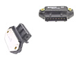
[Greg Shutt/Bob/Don Foster] Open your hood and look for the coil. If it's a Bosch system, the coil will be a cylinder mounted on the passenger-side firewall. If it's Rex/Regina, the coil will look more like a square transformer thing mounted on the driver's side strut tower. The "air mass meter" is another difference. The Bosch air mass meter attaches at the air cleaner box and has a large hose going to the intake manifold. It should have a 5 wire connector. Regina system has a similar looking device which is an intake air temperature sensor attached to the air box with a hose going to the intake manifold. Instead of a 5 wire connector, it has a 2 wire connector. The illustration to the right shows the Rex-Regina system components. See also Fuel Injection.
Note that the components for Regina differ from Bosch and you need to keep that in mind as you read FAQ notes. For example, the Rex system integrates the ignition power stage amplifier into the coil; Bosch has a separate unit.
Basic Operation and Troubleshooting of the EZ 117K[Don Willson]
This discussion is based on my 3 cars all of which have the EZ-117K Jetronic Ignition which is for the 4 cylinder engine, with distributor on the rear of the cam shaft, the timing signal is from the Hall effect sensor within the distributor or an RPM sensor on the flywheel, air is measured by an air mass meter, it has a knock sensor, and throttle position switch.
I have had three 740s and though I am not a
professional mechanic I'm a pretty good DIYer. I seldom use a dealer or
independent shop unless time or tools require it. I am an engineer and
like to know what's wrong and how that affects the engine My basic
reference are the Volvo shop manuals, especially the electrical, engine and
ignition manuals.
[Editor's Note: see the section on Maintenance Manuals for
more details on how to obtain the correct versions for your car.]
I will try to show a systematic approach to based on a chronological order where applicable.
Starting: Turn key to "run"
Power is supplied to the IGNITION CONTROL UNIT , hot side of the COIL, POWER STAGE, and most accessories.
Turn key to "start". Power is removed from most accessories and applied to the STARTER SOLENOID. (if the car is equipped with automatic transmission it must be in Neutral or Park)
The starter pinion gear meshes with the ring gear, the high ampere connection made and the starter motor operates.
Engine turns over. The sequence of events is as follows.
IGNITION CONTROL UNIT (ignition computer) sends power to the DISTRIBUTOR.
The HALL EFFECT sensor in the DISTRIBUTOR (LH2.2 systems) sends a square wave electrical signal that varies from 5 to 0 volts back to the IGNITION CONTROL UNIT. As the signal rises from 0 to 5V the control unit starts to compute the timing of the next ignition pulse. As the signal falls to 0V the control unit commences ignition countdown and delivers ignition pulse as computed. [Editor's Note: this is true for pre-88 cars; newer Volvos with LH 2.4 use an RPM SENSOR at the flywheel for the same effect.]
When the IGNITION CONTROL UNIT gets this signal it says "the engine is turning over, let's give it some fuel and spark" (I presume this is a safety function so that in case of an accident the fuel will not be delivered to a dead or damaged engine.). It sends the appropriate signal to the:
POWER STAGE (ignition amplifier). This feeds the coil which then send high voltage to the center tap of the distributor where the distributor sends the high voltage on to the correct spark plug.
FUEL CONTROL UNIT (LH-Jetronic.) This unit collects signals from the AIR MASS METER (AMU), COOLANT TEMPERATURE SENSOR, THROTTLE SWITCH, OXYGEN SENSOR (Lambda sond), and:
grounds the FUEL RELAY which (hopefully) turns on both the IN-TANK FUEL PUMP and the HIGH PRESSURE FUEL PUMP.
Fuel then flows under pressure, in the 30 to 40 PSI range (though the pump is capable of pressures up to 80 PSI), into the fuel rail. At the front end of the fuel rail is a PRESSURE REGULATOR that maintains a pressure in the 30 PSI range though it varies according to engine vacuum. A higher vacuum, as when idling or running lightly, allows more fuel to flow back to the tank and the pressure is reduced in the fuel rail. When under higher pressure or even turbo boost the pressure in the fuel rail is higher and more fuel is delivered for the same amount of injector open time.
Opens the INJECTORS for the appropriate time. Note, since this is not a sequential fuel injection system, all INJECTORS fire at once and timing is not an issue other than that they fire each half resolution, so that fuel is in the intake manifold ready for any intake valve to open.
Now
the engine starts, however, there is more to it.
If the engine is cold, like the first start in the morning, the AIR CONTROL VALVE opens and acts like a fast idle cam on old non fuel injected cars. The controlling signal on this is the COOLANT TEMPERATURE SENSOR. Generally only a few seconds is needed for this to be open, however, under some conditions it closes, the idle speed drops significantly and it opens again.
There is no choke but since the choke only forces a rich mixture the FUEL CONTROL UNIT will open the injectors more times and/or for longer periods.
As the engine warms up various signals are supplied to the FUEL CONTROL COMPUTER to modify the INJECTOR open time. For example:
The COOLANT TEMPERATURE SENSOR sends a signal to the FUEL CONTROL COMPUTER that less enrichment is needed (like a choke backing off)
The AIR MASS METER supplies the engine load as it measures the amount of air being delivered to the engine, as a function of the THROTTLE position, and sends this signal to the FUEL CONTROL COMPUTER for use in determining the optimum mixture
The OXYGEN SENSOR warms up and begins to send a signal to the FUEL CONTROL COMPUTER that in real time varies the mixture to maintain a mixture that delivers power with minimum emissions.
The KNOCK SENSOR 'listens' for the characteristic sound of a knock and sends a notice to the IGNITION CONTROL UNIT which retards the spark in steps of 2.8° up to 10° to 16°, until knocking ceases. Then it advances the spark in steps of 0.37° until, if possible, it return to the normal advance.
After fully warmed up and running the COOLANT TEMPERATURE SENSOR is continuously monitored and if it indicates an overheat condition it advances the timing by 13° if the throttle is closed on the B230FT engines.
The THROTTLE SWITCH senses when the THROTTLE is closed, foot off of the gas, on of two things happen:
If
the engine is turning over rapidly, above idle speed, the spark and fuel are
adjusted to give the maximum engine braking.
When the engine drops to near idle speed the
spark is retarded so as to provided a smoother idle.
After Shutting Down
One item occurs after the key is turned off, that is that a voltage is sent to the AIR MASS METER to burn off contaminants that have accumulated.
[Courtesy of Don Willson]
Using OBD Codes to Troubleshoot EZK Ignition Problems in Later Bosch LH2.4+ Systems See Engine: Diagnostic Codes for instructions on how to read both ignition and fuel injection computer trouble codes from the diagnostic boxes in later Bosch LH2.4 systems.
Using Diagnostic Outputs to Troubleshoot EZK Ignition Problems in Earlier Bosch LH2.2 Systems.
Despite not having a diagnostic box, you can still read some trouble codes using an LED diagnostic reader. See Engine: Diagnostic Codes for instructions. You can also follow the steps below, depending on your ignition model, to test various ignition components and pinpoint faulty units using simple electrical tests.
Renix-F (B200K)
At Connector A:
| Measurement Test | OK if: | Diagnostic Notes |
|---|---|---|
| Terminal 3 & Ground | >= 9.5V | Check fuse #12 and connector at A-pillar |
| Terminal 2 & Ground | <= 0.1 ohms | Check connector at LH wheel housing |
At Connector B:
| Measurement Test | OK if: | Diagnostic Notes |
|---|---|---|
| Terminals 4 & 5 | 220ohms +- 60 ohms | Check/replace pulse generator |
At Connector C:
| Measurement Test | OK if: | Diagnostic Notes |
|---|---|---|
| Terminal 8 & Ground | should have voltage w/ ignition advance relay engaged (car ) | - |
At Control Unit (in drive or A/C engaged)
| Measurement Test | OK if: | Diagnostic Notes |
|---|---|---|
| Terminals 3 & 9 | <= 0.1 ohms | Check/replace unit |
At Coil.
| Measurement Test | OK if: | Diagnostic Notes |
|---|---|---|
| Primary coil windings: | 0.6 +- 0.2 ohms | - |
| Secondary coil windings | 4000 +- 1500 ohms | - |
EZ 117/118 Series for Bosch LH2.2
At Power Stage Connector:
| Measurement Test | OK if: | Diagnostic Notes |
|---|---|---|
| Terminal 1 & Ground | 12V w/ ignition on when rotor is firing | Check fuse #12 and connector at A-pillar |
| Terminal 4 & Ground | 12V w/ ignition on | Check connector at LH wheel housing |
| Terminals 1 and 4 | Resistance matches coil specs | - |
| Terminal 2 & Ground | 0 ohms | - |
| Terminal 5 & Ground | 2V w/ leads disconnected from coil terminals 1 & 15, when operating starter motor | - |
At EZK Hall sensor wiring:
| Measurement Test | OK if: | Diagnostic Notes |
|---|---|---|
| Terminal 3 (red) & Ground | 12V w/ ignition on | - |
| Terminal 2 (blue) & Ground | 5V w/ ignition on | - |
| Terminal 1 (black) & Ground | 0 ohms | - |
EZK coil resistance:
| Measurement Test | OK if: | Diagnostic Notes |
|---|---|---|
| EZ-102K | 0.6-0.9 ohms (pri), 6500-8500 ohms (sec) | |
| EZ-115K | 0.6-1.0 ohms (pri), 6500-9000 ohms (sec) | - |
| EZ-117/118K | 0.6-0.9 ohms (pri), 6500-9000 ohms (sec) | - |
For EZ-102K (B23FT)
At ICU Connectors:
| Measurement Test | OK if: | Diagnostic Notes |
|---|---|---|
| Terminal 1 & Ground | 12V w/ ignition on | - |
| Terminals 1 & 11 | 12V w/ ignition on (#11 is ICU ground lead) | - |
| Terminal 5 & Ground | no continuity (test connector) | - |
| Terminal 4 & Ground | 0 ohms w/ throttle closed, increased resistance w/ throttle open (TPS) | - |
| Terminals 8 & 15 | continuity w/ leads at knock sensor connector jumped | - |
| Terminal 14 & Ground | approx 11V w/ ignition on (load signal from ECU) | - |
for EZ-115K (B280E/F) / EZ-117K (B230F/B230FT) / EZ-118K (B200E/B230E/K)
| Measurement Test | OK if: | Diagnostic Notes |
|---|---|---|
| Terminal 6 & Ground | 12V w/ ignition on | - |
| Terminals 6 & 20 | 12V w/ ignition on (#20 is ICU ground) | - |
| Terminal 20 & Ground | 0 ohms (ground) | - |
| Terminal 3 & Ground | no continuity (test connector) | - |
| Terminal 7 & Ground | 0 ohms w/ throttle closed, non-zero w/ throttle open (infinite resistance should not be seen at the ICU) (throttle switch) | B230FT, B280 only |
| Terminals 7 & 11 | 0 ohms w/ throttle closed, infinite resistance w/ throttle open (throttle microswitch) | not B230F/FT |
| Terminals 11 & 25 | 1900 ohms w/ coolant at 22C Terminals 12 & 13: continuity w/ leads at knock sensor connector jumped | B230K only |
| Terminal 8 and ground | approx. 11V w/ ignition on. (load signal from ECU) | B230F/FT, B280 only |
| Terminals 10 & 23 | 500-600 ohms (crank position sensor) | B280 only |
| Terminal 2 & Ground | proper resistance for coolant temp (coolant temp sensor) | B280 only |
| Terminals 12 & 13; 24 & 25 | continuity w/ knock sensor connectors jumped | B280 only |
| Terminals 18 & 19 | 0 ohms (Cyl #1 sensor) | B280 only |
Car Won't Start; Ignition Diagnosis.
[Problem:] This morning my 86 740 GLE (B230F) started and ran for approx. 30 seconds then died and will not restart. No spark exists at the coil (replaced coil with new one no change). The fuel relay does kick on after taking the ignition switch from start to run. [Response:] Ok let's go thru a general no start fault trace:
- Is the transmission in a gear other than "Park"?
- Is there gas in the tank?
- When you turn the key on does the pump run for about 1 second? From your post I would assume that the answer is yes. This indicates that the fuel pump runs and the relay and ECM are capable of turning it on.
- When you put the engine to crank does the pump run during the cranking? Again you said yes, as you deduced this indicates that the hall switch is working
- Iis there spark at the coil itself? (to test pull the coil wire part way out and have someone else crank the engine) If the answer is yes then the problem is in the distributor secondary (cap, rotor, wires) If the answer is no continue.
- Is there voltage present at the coil low tension terminals with the key on? ( and are all the wires connected?) If no fix, if yes continue
- Is the power stage connected? yes? remove the connector and examine the terminals on both the power stage and connector if they are corroded they will need to be cleaned. Still no start continue.
Regina-Equipped Cars: [Chris Herbst] The coil, which is an expensive beast ($200), will (here is the voice of experience) cause random no-starting though not stalling. See Bosch vs. Regina for identification.
Ignition Failure after Hot Soak: Won't Re-start
[Symptom:]My 1988 744 Turbo with EZK 117 ignition starts and drives fine with A/C on in 95 degree Maryland weather for about 30 minutes. It won't start once it is turned off. A strobe test shows no spark. It sits for several hours (cools down presumably) and then starts right off. In its disabled state there is system voltage registered at both sides of the coil and at terminals (1) and (4) of the Power Stage amplifier.
Diagnostic Tips. Next time you have a hard ignition failure pull a plug wire, insert an old spark plug, ground the outside and check for spark. If you don't have it, go to the coil center high tension lead and check for spark. Next ground the coil's high tension lead and put a meter on the coil's 12v terminals. No 12v switching? Since most systems apply 12v and switch the ground lead, if there is no 12v at all, check the power lead to the ignition, wiring, fuse etc. If you do have 12v but no switching then check the Hall sensor in the distributor. Disconnect the leads from the reluctor (in the distributor) from the ignition module and measure with a sensitive DMM. You should see some small voltage as you crank. At this point you've checked the power to the ignition module, the sensor, and the spark delivery path. That means the only thing left to do is repair/replace the ignition module.
Diagnosis: LH 2.2 Systems. First, check for a cracked and/or oil-contaminated harness connector on the side of the distributor. If this is okay, then replacement of the Hall Sensor in the distributor is the fix. Heat rises in the stopped engine and increases temperature of the rear-top-mounted distributor. A weak Hall breaks down and ceases to send pulses to ignition control module; hence, no spark. Be careful not to bung-up the rivet holes in the distributor body when you drill out the Hall attachments; you need a good lip for the new sensor rivet ends to crush against. Mount two bolts in a vice and use them as supports for the inner ends of the rivets as you mash the outer ends with a drift.
[More on Hall Sensor:] Best idea when replacing the Hall Sensor is to take the whole unit (just the bracket) to a dealer and ask them to drill the old one and put the new one in. The rivets on the Hall are harder than the aluminum bracket plate so if your drill slips out you will have to buy a new distributor cause you can not buy just the bracket. If you replace it yourself, you will need the help of a second person to put the sensor back on. It has 2 rivets that need to be drilled out. When you place the new one on you need a second person to hold it squarely over a punch so you can peen the rivets in place. There are instructions in the Volvo manuals. Be sure to note the way the collar with ears comes off.
[Contrary Opinion on Hall Replacement:] Although Volvo sells the Hall sensor separately from the distributor assembly, a new distributor is usually more cost-effective for two reasons: First, installing the mounting rivets in a new sensor is awkward, tedious work . Because the sensor location prevents you from getting a straight shot at the rivet heads, it's very difficult to drive the rivets in securely. Second, bushing wear is common in higher-mileage Volvo distributors. You can usually feel the wear-lateral movement in the distributor shaft-with the distributor removed from the engine. A sloppy distributor shaft usually goes hand-in-hand with distributor oil leaks, especially through the seal protecting the inside of the distributor.
Diagnosis: LH 2.4 Systems. No-hot-restart problems are almost always due to failures in: fuel injection relay, radio suppression relay, or rpm sensor.
Does My Car Have a Hall or RPM
Sensor? You can quit worrying about the Hall sensor if you have a 89 or
later non-turbo or 90 or later turbo: the last years for the Hall sensor were 1988 and 1989, respectively. The Hall sensor is gone in favor of the
RPM sensor on top of bell housing. In these cars, there is no plastic wiring
connector on the side of the distributor plate and no wires into the
distributor other than the high-tension spark leads to the cap.
The illustration shows the Hall Sensor distributor
and the arrow depicts the sensor.
Testing Hall Sensor. Failure Modes. The Hall Sensor distributor can fail through broken wiring insulation, a broken wiring connector at the side (this embrittles over time due to engine heat), or a failed Hall Sensor.
Quick Hall sensor test: [Note from Dave] the tachometer needle does jump slighty as you crank engine over if the Hall sensor is working, but the needle lays dead if the sensor is not working.
Full Hall Sensor Test: Undo the distributor connector. When the ignition is ON the Voltage between positive terminal (red lead -Nr. 3) and ground should be approx. 11V. Voltage between (blue lead - Nr.2; middle one) and ground should be 5V although if you put it on a scope you would see the sharp rise and fall from 12v to ground as the distributor rotates. Pulse frequency varies as rpm is increased. . Resistance between (black lead - Nr. 1) and ground should be close to zero Ohms. Undo connector from the control unit (above the brake pedal) and remove the sealing washers (plastic inserts on the side of the connector). Replace connector without cover or sealing washers.
- Disconnect the/red and blue leads from ignition coil. - Measure voltage between terminal 24 at rear of control unit connector (blue lead) and ground. NOTE: Connector must be attached to control unit. Switch on ignition. Turn crankshaft by hand. Voltage should indicate OVER 1.8V each time a vane passes Hall generator. Instrument should read approx."0" (0 - 0.7V) each time an opening passes Hall generator. The correct voltage is less than 0.7V or more than 1.8V.
Replacing RPM or Hall Sensors.
RPM Sensor: If your car is a non-turbo 89+ or turbo 90+ model then it has a flywheel reading RPM/Position sensor that is down below the rear of the cylinder head, mounted on the bellhousing through a bracket retained by one bolt that should be a 10mm head on a 89. It is connected to wires above the engine on the firewall.CAUTION: [Chris Herbst] Never pry the RPM sensor out of the flimsy internal bracket to which it is attached. Spray a tiny bit of penetrant around it if you have to, but not enough to leak down on the clutch if it's a manual trans car. And if you have the trans out for any reason, take the RPM sensor out--whether or not you reuse it--and coat it LIGHTLY with a film of grease. That will avoid the problem, should the sensor need replacement in the future. See Crank Position Sensor for more information.
Hall Sensor: If it is 89 turbo or pre-89 NA then it has a Hall switch that is in the distributor to sense engine rotations. The Hall switch is tough as it requires that you knock out a pin and pull out the shaft, then VERY carefully drill out a couple of pins that retain the hall switch. Then you have to be very careful about supporting the distributor base while bradding the retainer pins to retain the new hall switch. If you slip while bradding the pins then you punch out a hole in the base and then you need a new distributor. [Response:] Changing that is not for the novice. It is riveted into the distributor. Some dealers offer rebuilt exchange on the distributors. Before you jump to the hall sensor, carefully examine the wires from the firewall to the distributor, which sometimes break inside from years of flexing. These can be repaired with a little work. Also, check the brittle plastic connector where the wires go into the distributor. This can cause intermittent shorting. The plastic fitting is Volvo PN 1346793, about $3.00 as I recall. If you are going to remove the distributor for any reason, carefully scribe a mark to return it to its exact former position so as not to change the timing (the holes in the distributor are slotted). Finally, check for any shaft wear on the distributor: wobbling is abnormal.
Removing the Distributor Shaft. [Response: John Sargent] The hardened pin in the drive dog can be tough to remove in order to take out the shaft and tigger wheel. I have a drill press vice which has a V-groove in it for gripping shafts. I clamp the shaft in the drill press vice, and drive the pin out. You will have to have a good pin punch of the right size. You may break or bend a pin punch that is too small. Take carefull note of the previous post regarding the rivets. The pot metal base is easy to damage. A good alternative is to buy the base complete with Hall sensor and seals from IPS in Boise for just under $100. The Hall sensor runs over $60 from Volvo, and RPR quoted me about $90.
[Jim] Mark the slot drive in relation to the rotor notch- it can be installed 180 degrees out. Punch the retainer pin out- use a good punch and a solid surface to support the drive. The pins can be quite tight. Remove the drive, collect and count the thrust washers, remove the shaft from the housing and collect those washers too. There may be some fiber washers which are not replaceable. There is a serrated steel washer peened into the aluminum housing- pry it out, trying not too bend it too badly- It can be straightened with a hammer if need be. Pop the seal out, clean the housing, push the new one in, carefully tap the steel washer in ( don't worry about peening it in- it can't go anywhere anyway. Assembly is reverse of removal.
Replacing the Hall Sensor.
[Response: Jim] Plan to use a Dremel or die grinder
to grind off the two rivets or you will punch out the thin aluminum of the
housing, and will be buying a new distributor. [Response:] I've done few of
these. Never alone, however. Drill out the old rivets carefully and pry
out the sensor. Next, have an assistant you can trust with approximately
$ 70.00 hold the new sensor in its proper place on the distributor plate.
Place a steel punch of roughly same diameter as the rivets into the bench wise.
Have the assistant hold the D. plate in such a way that the rivet is directly
over the punch. Now, YOU, using the second punch and a hammer CAREFULLY
hit the top part of the rivet. It will take MANY hits since these darn rivets
are made of steel. The key here is steady hands, and frequent breaks. One wrong
move, and you are done. Simple physics tell you which, steel or aluminum will
crack first under constant hammering. This is akin to putting a horse shoe
onto an a hard boiled egg, possible but very nerve wracking. [Response:
Jim] To rivet the new sensor in place, take a 5/16 bolt about 5 inches long and
drill a depression in the end of it to just fit over the end of the rivet in
the new switch. You also must grind the end down in diameter so it is only
supporting the rivet, and not touching the plastic. Grab the bolt in a vise,
get a friend to hold the distributor in place, and carefully peen the rivets. I
have a very small chisel that works well, or a centerpunch will do the job.
Don't overtighten the rivets- all that is needed is to keep the switch solid.
[Response: DanW] Don't let these warnings scare you off. It is really not
a difficult job. When I replaced the hall effect sensor on my daughter's car, I
followed the advice of my local mechanic and instead of peening the rivets I
used JB Weld to fasten the new sensor in place. There are two or three O-rings
that you should also replace. Replace the sensor connector and plastic ring
which keeps the wires out of the rotating sensor wheel. My own caution: There
are steel and fiber washers on the shaft. Keep track of their order and be very
careful with the fiber washers. They are fragile (Don't ask.) and no one seems
to have replacements. This is not a tough job. Just be careful and you can save
yourself about $200 in parts alone. I bought new plugs, wires, cap, and rotor
when I did this job. Total cost was about $200.
Reliability Tip. I would throw in a junkyard distributor to get back on the road, rebuild the original distributor with a new sensor, seals etc. at my leisure, and then swap in the rebuilt unit. This is one of the very few failures that can stop your 740 completely, so a big confidence boost can be gained by having a good spare distributor on board. It's hard to reach, but a practical road-side repair to change distributors.
Hall Switch Distributor Connector.
While replacing the distributor cap and rotor on the 87 764T the Hall switch
connector at the distributor cracked off some of the old plastic and wouldn't stay on the distributor base. Didn't
crack any wires/insulation. This distributor is used at least through 90 (my 90
740T has the part) and so did an 86 B230FT engine I used the long block on the
87. (Illustration courtesy of Mike Ponte)
and wouldn't stay on the distributor base. Didn't
crack any wires/insulation. This distributor is used at least through 90 (my 90
740T has the part) and so did an 86 B230FT engine I used the long block on the
87. (Illustration courtesy of Mike Ponte)
Removing the Wires. [Jim] The black wire retainer is usually broken away from the housing. I have found the best way to get the wires out is to VERY carefully grind the plastic away, finishing with the wire wheel, until the tab holding the individual wire in is free. Don't mix the wires up- the new housing is marked + and -. The white wire holddown will come off with a little screwdriver work.
Repair. The repair was quick and dirty...I mixed up some loctite filled epoxy and glued in the connector. The stuff sets up quickly and I baked it at warm (lowest possible setting) in the kitchen oven for 5 minutes. Seems to be working since I put it together and am driving the car. If it blows I still have the distributor from the 86 engine with the unbroken connector. [The plug is available at the dealer. I got one a year ago. I think I paid $6.00.]
Wiring at the Connector. [Tip from John Sargent] Here is the correct wiring at the sensor connector in case your wires came out. Looking down on the top of the distributor, with the Hall effect connector down, left to right: black, green, red.
Distributor R&R and Shaft
Seal Replacement. Oil leakage from the distributor on engines with
camshaft-mounted distributors usually originates at the distributor shaft
o-rings. High engine temperatures can cause these o-rings to shrink. There are
three seals: two outer o-rings and an internal shaft seal under the drive dogs.
[Editor's Note: See Michael Ponte's excellent illustrations at http://www.mikeponte.com/volvo/dist.htm
These picture a pre-89 distributor with a Hall switch, but are similar to newer
ones as well.] Copies below:
[Inquiry:] I have the beginnings of an oil leak at the distributor o-rings (just beneath the shaft on the B230F distributor.) According to Chilton's, it's easy to pull the cover, cap and rotor, remove the shaft, and pull the distributor out to replace both the big dust cover o-ring as well as the smaller o-ring inside on the shaft. Has anyone actually done this? Is access a problem? How about replacing the distributor: do you have to pay close attention to shaft alignment?
[Another Related Inquiry regarding Timing:] My distributor appears to be seeping a small amount of oil on my 93 940 (sohc engine). I noticed this while doing the 90 kmiles service. I also noticed the PO or his mechanic ditched the plastic dust shield. First thing Monday, I'll get the dust cap as I'm thinking it will keep the rotor and inside the cap clean. But I'm thinking maybe its time to replace those nasty o-rings. Just one question, my book claims the timing is not adjustable. I'm kind of wondering how do I set the timing, if I pull the distributor and replace those o-rings? I can't find any info on this in my books.
Removing the Distributor: [Editor's Note:] The spark plug high-tension leads will probably be tough to remove if you did not use dielectric grease on the boots last time they were installed. Gently pry up the boots about one centimeter with a blunt blade that won't scratch the cap, then pull them off while holding the tops of the boots. [Response 1: Don Willson] Mark the spark plug wires and the Hall connector down below (if your car has one) and push the connector "hair pin" in and pull down. Remove the three cap screws with an 8 mm metric open end wrench. The screws in the cap are captive and will not drop out. [Hall switch distributors: Mark the position on the locking screws on the adjustment slot. Non-Hall distributors have a self-aligning plastic device, but you may want to mark the location of the distributor on the cam anyway] Pull the cap straight back. Remove the two 10mm distributor plate bolts. Pull distributor straight out the back, noting the position of the plate, rotor and offset eared drive cog. Draw a diagram so you can reinstall everything correctly and not 180 degrees out of alignment. Now is the time to test for shaft wear and wobbling.
O-Rings:
There are two outer o-rings on the distributor shaft visible when you pull out
the distributor. [Kevin Lawlor] The small o-ring fits on the end of
the shaft and the large o-ring fits on the  housing. Use a little Vaseline to install
easily. [Tip from JohnB] There are three O-rings, but the inside one (the
center shaft seal, see below) is almost impossible to replace, just forget it.
The big O ring on the housing is generally the leaker and the little ring on
the shaft helps to keep oil out of the distributor itself.
[John Sargent] According to Volvo TSB of March, 1988,
you should use the green o-rings made of improved elastomer rather than black
rings.
housing. Use a little Vaseline to install
easily. [Tip from JohnB] There are three O-rings, but the inside one (the
center shaft seal, see below) is almost impossible to replace, just forget it.
The big O ring on the housing is generally the leaker and the little ring on
the shaft helps to keep oil out of the distributor itself.
[John Sargent] According to Volvo TSB of March, 1988,
you should use the green o-rings made of improved elastomer rather than black
rings.
Center Shaft Seal There is a center shaft seal inside the distributor plate that dries out and leaks oil. This shaft seal is hard to find.
Where to Find Center Shaft Seal: [Randy Starkie] Get the entire aftermarket seal kit from FCPGroton for about $3. [Tip from John Sargent] If you have distributor shaft seal leaks in the 700 series with B230 engines (cam driven distributor on rear of head), the distributor o-rings are available from Volvo, but the shaft seal is not. A few weeks ago I even looked in the parts manual, and the shaft seal is not shown. Jim found that Honda part #91205-KF0-003 is a replacement for this seal. It works perfect. However, it is not stocked by many Honda mower dealers, and some want a $7.50 service fee to order a non-stocked part. The seal is about $2.50 US from Honda (#91205-KF0-003 Honda or Transcom #12X20X4TC). This seal is simply a metric seal, 12mm X 20mm X 5mm. It is for a 12mm shaft, it is 20mm OD, and 5mm thick. It is also a rubber coated (that's good) seal with two lips. As near as I can tell, the original seal Volvo used came both rubber coated and non-coated, and appears to be a single lip seal although I can't tell for sure. Now for the substitutions. Chicago Rawhide seal 4701 is exactly the same with a single lip. Transcom seal #12X20X4TC is a double lip seal, rubber coated, that is 4mm thick. That is what is in the distributor in my wife's 745T. When I installed the seal, I set it with the outer edge flush with the distributor housing. There is a 1mm gap behind it which won't hurt anything. You could also set it all the way back in the housing, and it should also be fine. It fits tight, and I doubt that it would ever move out against the seal retainer. The Transcom seal cost $1.82 US from a local bearing sales house. For those of you who can't get those brands of seals, simply contact a bearing supply company and tell them you want a 12mm X 20 mm X 5mm seal, preferably rubber coated with double lips.
How to Replace Center Shaft Seal:
See John Sargent's excellent illustrated procedure to understand how to do this. [Procedure from Jim] To do this job, you need the seal (see above). Most likely, this is a good time to change the Hall sensor as well: see below.
Here are the basic instructions- ignore the bits about the parts you are not changing. Remove the distributor cap, rotor, and plastic shield, and remove the distributor from the head. Mark the slot drive in relation to the rotor notch- it can be installed 180 degrees out of alignment. Punch the retainer pin out- use a good punch and a solid surface to support the drive. Use a tapered punch to get the pin moving, then lube the pin and chase it out with a straight pin punch. Straight pin punches often bend and break when you initially use them to get the pin moving.The pins can be quite tight and it takes some determination to drive it out. For a special tool to do this, see the Special Tools FAQ section. Remove the drive, collect and COUNT the thrust washers, remove the shaft from the housing and collect those washers too. There is a serrated steel washer peened into the aluminum housing- pry it out, trying not too bend it too badly- It can be straightened with a hammer if need be. Pop the seal out, clean the housing, push the new one in, carefully tap the steel washer in (don't worry about peening it in- it can't go anywhere anyway. Assembly is reverse of removal. [Contrary thoughts from Chris Herbst] Can I make a logical suggestion straight from the shop? Replace the whole distributor. On an 89 it is not an expensive proposition because there's no hall effect sensor on the distributor. The distributors for the later models are much less expensive, and you will drive yourself crazy trying to repair the inner shaft seal in the distributor as it is now. I hate that job and have since given in to replacement, which is often against my basic principles. In this case, it's such a breeze to replace the whole distributor that it wouldn't make sense to replace the center seal. Fiber Washers. If you have fiber washers in your distributor and you break one or more during removal, go to Home Depot or a hardware store, buy some similar washers, and drill or file and hand-sand the inner hole until it fits the shaft. Mylar washers in particular fit well, being very thin. The dealer will often be of no help with these small parts.
Shaft and Driver Orientation: Mark all removed pieces and their orientation. The cogged driver can be installed 180 degrees in reverse and the car will not start. The offset drive cogs on the driver should be toward the same side of the shaft as the slot for the rotor cog.
[Pin Removal Tip from Tom Irwin:] The solid pin should be much easier. Generally, pressing the pin out with static force works better than shock force. Use a vise with a counterbored block of solid material in the rear jaw to support the shaft against compressive force, then at the front jaw, use a hardened pin or drill bit as a drift and squeeze it up gently. A large nut in the rear jaw should be all the fixture you need, maybe Dremel it out to roughly match the contour of the shaft. When the pin extends enough out of the shaft, grab it up with a vise grip and yank it out.
Older Distributors using Hall Sensors:
Wiring Connector Repair. While
the distributor is off check the 'housing' carefully...that's the official
Volvo part name for the little black connector that has three blades in it that
connects the Hall effect sensor to the wiring harness. It's about $3.00 or so
and breaks down in 10 years of oil and heat and engine washes.
It's fairly difficult to reinstall...strong fingers
and a pliers required. Needle nose maybe to pull the blades entirely into the
housing once the housing is on the distributor body. But the housing
replacement is thoroughly gratifying if the connector was just hanging there.
FWIW, I tried to repair/replace the housing with epoxy and it just didn't
hold. [Tip: JohnB] The black plastic housing for the ignition
trigger connector is replaceable...you don't need to get a new distributor to
replace it. Highly recommend you replace it.
Older Distributors using Hall Sensors: Hall Sensor Replacement
Fix or Buy? [Tip from Bruce] The procedure requires some skills (see Jim's remarks below.) If you can locate a Bosch aftermarket source or an independant Volvo repair center try to get a complete new distributor, cap and rotor as one unit. They are not cheap. Price out the Hall switch, o-rings and cap and rotor. You may not be much less that the price of a complete new unit. Shop around for a Bosch service center or and independent Volvo repair center who may sell you the complete Bosch unit cheaper that a Volvo brand unit.
Hall Sensor Replacement Procedure. [Tips from Jim] If you rebuild the distributor shaft seals, then it may be a good time to change the wire connector for the hall effect switch, Volvo p/n 1346793, and the hold-down for the wires to keep them fron hitting the rotating parts, Volvo p/n 1346794. In case you are not aware of it, the hall effect switch is available separately from the housing for a bunch less money than a whole distributor, too. Volvo p/n 1346792. A few blacksmithing skills are needed for that part of the job, but it is not too tough. I have found the only way to check the hall switch is with a lab scope, but also find that a car with 250,000 km or more almost always runs better with a new one. I guess after it has turned on and off a couple of billion times, the magnet or transistor or whatever starts to get weak, and won't give a clean voltage change.
The black wire retainer is usually broken away from the housing. I have found the best way to get the wires out is to VERY carefully grind the plastic away, finishing with the wire wheel, until the tab holding the individual wire in is free. Don't mix the wires up- the new housing is marked + and -. The white wire hold-down will come off with a little screwdriver work. To change the hall switch, there are two tricks- the first is to use a Dremel or die grinder to grind off the two rivets. Otherwise, you will punch out the thin aluminum of the housing, and will be buying a new distributor. I know this, because I have a test unit at the shop with the switch epoxied in! The other trick is to take a 5/16 bolt about 5 inches long and drill a depression in the end of it to just fit over the end of the rivet in the new switch. You also must grind the end down in diameter so it is only supporting the rivet, and not touching the plastic. Grab the bolt in a vise, get a friend to hold the distributor in place, and carefully peen the rivets. I have a very small chisel that works well, or a centerpunch will do the job. Don't overtighten the rivets- all that is needed is to keep the switch solid. For this part of the job, somebody who has riveted things in the old days with a hammer can be a useful ally.
Newer Distributors using RPM Sensors: [Response: Abe Crombie] The ignition system uses a crankshaft reading RPM sensor for timing. The distributor has no bearing on timing. Take note of the position of distributor by looking with a mirror at the relative length of distributor adjustment slots where bolts go in. You may not need to do this as there should be a plastic piece in one of the bolt holes that positions the distributor housing. The distributor only goes into cam in one possible position due to the offset slot that drives distributor via an offset eared piece. When you pull distributor shaft out to replace the shaft seal take careful note of position of the eared drive cog so it can be put back in the same place and not 180 degrees off.
Re-installing the Distributor: Put new O-rings on (big one on housing and little one on shaft lubed with Vaseline) and use antiseize on the aluminum housing bolts. Use antiseize paste on the aluminum body of the distributor, just a fine film will do...helps to get it out next time.
[Editor's Note: the newer distributor uses a black plastic alignment insert in one of the mounting flanges that centers a 10 mm fastener - setting it right for both sides, to ensure the distributor is re-installed correctly. Don't move this fitting when you disassemble the distributor] The rotor is installed in one direction only, matching the slot on the shaft with the ridge inside the rotor. [John Sargent] Take the cap off before installing the distributor. Use engine oil as a lube on the distributor base and o-ring. When you turn the rotor to where the drive cog matches the cam, the distributor will slide into place. Push it in using your fingers positioned near the inner circumference of the distributor, not the outer portion. If it does not slide into position, the cog is 180 degrees out of phase. [Tom Irwin] If you didn't have the plastic fitting or failed to mark the location of the distributor on the head, don't worry. The ECM will make enough correction to get around almost anything you have done. Try and look at the surface of the flange and see if you can tell where the clamping bolt was seated. Aim for that. If all else fails, you could disable the electronic advance and base time the thing. I really don't think it will matter much. If in doubt, aim for the middle.
Make sure you have a dustcap installed under
the rotor....it serves to keep crap from the hall sensor innards as well as oil
from the engine from getting to the inside of the distributor cap. I found out
a year after the dealer had re-O-ringed the distributor and replaced the
ignition wires (don't ask...I now do my own O-ringing there) that the clown had
left off the dust cap. It's a few bucks at the dealer too...un-obtainable at
auto stores. The dust cap is pre-installed on Bosch caps.
Use silicone dielectric grease on the spark high-tension lead boots to make
both installation and removal easier. Use your finger to align the metal
lead in the boot into the cap, then push down hard. It snaps home when
correctly installed and you cannot easily pull the lead back off. If it
won't snap home, then make sure you have not bent the metal connector.
Re-installing the Hall Sensor Distributor: Check your timing when you put it back...I found out mine was at 5 degrees BTC vice the 12 in the manual...makes a noticeable difference in bottom end torque when you launch!!!
[Inquiry:] During periods of great humidity while driving at normal operating temperature, engine cuts out and then after a second or 2 (sometimes more) it picks back up or stalls. If it stalls sometimes it will start back up sometimes it won't; In this situation (not starting back up) engine turns over but absolutely no ignition. This model is a 760 with turbo and intercooler.
[Response:] The secondary ignition parts are the first suspects for your trouble. The rotor can develop a hole from spark hunting a place to go. The hole will be from center of rotor where distributor cap contact touches through to underside where it sticks onto shaft. This effectively shorts out spark. If, when you say "no ignition" you mean no spark out of coil wire, then you needn't look at cap, rotor, & wires. Then look for arcing coil top. The coil can develop an internal short where the hole where coil wire inserts gets a crack that allows the spark to jump to one of the other leads killing spark. OR your hall switch is defective. If the hall switch or the hall switch (hall switch= sensor assy. inside dist) connector is the problem then you will see tachometer die INSTANTLY when problem occurs, i.e. tach drops to 0 before the engine actually quits turning. Corrosion at the power stage connector (black and gray unit wire connector behind and a few inches below headlight level on driver's side inner fender behind air cleaner if it's a non-turbo) will cause it to die with instant tach loss also.
Distributor Shaft Wear. [Andrew Smith] After noticing stumbling and misfire, I discovered that my distributor had mechanically failed at 110k miles: the shaft wobbled and allowed the rotor to contact the cap. A new distributor solved the problem. Check for this whenever removing the distributor.
Ignition Amplifier (Power Stage) Failure.
 Engine
Stops Dead at 60MPH. [Inquiry:
driving down the highway at @ 60mph with 1/4 tank of gas in 100 degree temp in
well kept 84 760 Turbo; car just dies, engine turns over but will not
start] [Response:] Well, when my '84 760 Turbo died for no apparent
reason as you describe, it was in the freezing dark, going over Donner Pass.
Everything on the car worked except no spark and the engine wouldn't run.
It turned out to be the ignition module, which is mounted on the inner driver's
side fender well, above the battery, close to where someone else mentioned the
ballast resistor was located. It's easy to get to and replace. If
that turns out to be the culprit, shop around before buying the new part.
Volvo dealers charge several hundred $$$ for this thing, but I found one from
an independent parts distributor for about $90 - the identical part made
by BOSCH with the same part number on it. See notes below on the use of thermal conducting grease during installation.
Engine
Stops Dead at 60MPH. [Inquiry:
driving down the highway at @ 60mph with 1/4 tank of gas in 100 degree temp in
well kept 84 760 Turbo; car just dies, engine turns over but will not
start] [Response:] Well, when my '84 760 Turbo died for no apparent
reason as you describe, it was in the freezing dark, going over Donner Pass.
Everything on the car worked except no spark and the engine wouldn't run.
It turned out to be the ignition module, which is mounted on the inner driver's
side fender well, above the battery, close to where someone else mentioned the
ballast resistor was located. It's easy to get to and replace. If
that turns out to be the culprit, shop around before buying the new part.
Volvo dealers charge several hundred $$$ for this thing, but I found one from
an independent parts distributor for about $90 - the identical part made
by BOSCH with the same part number on it. See notes below on the use of thermal conducting grease during installation.
Intermittent Ignition Failure.
Symptoms. As you are all well aware, intermittent problems are a b*tch to correct. However, last night, the car started fine but stalled halfway out of the garage and would not restart as has happened several times before. I've always suspected an ignition fault rather than fuel as the engine dies instantly when it happens. No sputtering, rough running or anything like that, it's like the key was turned off. Other Symptoms Which May be Related to This Failure Mode: The car will start and then die, or refuse to start again until it's cooled off, or just not start period. or just randomly die or misfire under load. However, note that no-hot-restart problems are usually related to failing fuel injection relays, rpm sensors, or radio suppression relays.
First thing I did was hook up my timing light and had one of the boys aim it at me while I cranked it over. No indication of currant flow in the plug wire. Now I can dismiss the fuel/fuel injection system (I think). Next I connect my Fluke Meter to ground and the positive lead to the positive side of the coil and switch on the ignition to the run position. No Voltage! I ran back into the house to get a jumper lead - I was going to run it directly from the battery to the coil but when I tested for voltage again it was there. Get in the car and it started right up and died before I could put it in gear. Open the hood and check for voltage at the coil and it's gone. Now, w/o touching the key (I'd left it in the run position), and without "tapping" anything with a hammer or "jiggling" any wires, I test both sides of the coil for voltage again. I test the positive side of the low tension ckt and it's 0 volts w/ respect to ground, test the other low tension lead and it to is 0 volts w/ respect to ground. Test the positive side once more and the voltage is back! Get in, start the car and it runs fine. Anyone know what might be causing this?
[Response: Randy Holst] From a similar experience I had with my (now departed) '84 760T, I would suggest that it is the ignition amplifier module, which is mounted on a heat sink on the inner driver's side fender well behind the headlight. At a very inopportune time and location, mine quit working when I closed the hood while the engine was running. The engine immediately quit as though someone had turned off the ignition. The result was no spark, no juice to the coil and no amount of fiddling around would change anything. (Long story about having the car towed, isolating the problem and having a replacement part flown in omitted.) Replacing the ignition control module cured the problem and it never reoccurred. [Editor] Test the ignition coil if this occurs to make sure it did not cause the failure.
Engine Stops: Loose Power Stage Amplifier Fails Due to Overheat: [Tips from Ian Afford/Peter Day] A month ago my 740 (B230E) died on me. The RAC man diagnosed a faulty Ignition Amplifier Module. He also pointed out that it was slightly loose on its mountings, which he suspected might have caused it to fail, the module uses the bodywork to conduct the heat away keeping it cool, and because it was loose it might have been overheating. So I suggest that you find this module (on my Bosch-powered engine it is fixed to the side of the engine compartment next to the air cleaner box) and check it is secure, it might also be worth removing it, cleaning and re-greasing the mating surfaces in order to achieve a good thermal contact. In order to allow the power output stage of the ignition amplifier to cool correctly, you need to apply some heat sink compound (thermal grease-see below) to both the flat mating surfaces between the amplifier case and the fender to improve cooling (see below). This will allow an even heat dissipation and prevent the transistors in the amplifier from overheating. You can buy the grease at Radio Shack or at an electronics supply store. Rex/Regina Note: In these systems, the power amplifier is integrated with the coil. See also the symptoms described in the Engine: Performance section under Power Stage Failure.
Engine Stops: Thermal Paste at Amplifier Module Dries Out. [Nick Heiny] The factory-installed thermal grease that conducts heat from the power stage amplifier can dry out over time and cause an amplifier failure. Replacing this paste as a preventive maintenance act can keep the power stage in good shape. A good choice is Arctic Silver 5 in the 3.5g tube for about $8. Spread a small amount on the cleaned back surface of the amplifier and remount on the fender.
Very Poor Idle; Power Stage Overheating: [Tip from Stephen C] After the engine heated up or when under hood temps are high, it would idle like crap and die frequently. I took a water hose and cooled the power stage down and it would idle great for 10 min+. Worth a try, just to see. [AlexZ] The power stage can fail in weird ways, resulting in odd running. Considering its price and ease of installation, you may as well replace it.
Thermal Grease Used to Remove Heat. [Chris Owen] Here's the Radio Shack product I've used for many years on the backs of ignition amplifiers on Volvos and German motorcycles, both Bosch systems: Radio Shack Heat Sink Compound (Grease), PN 276-1372. It's $2.99 a tube, enough to last years. Heat is the enemy of this part, and the compound helps wick away heat to the aluminum heat sink base. Cleaning the heat-transfer face and applying a thin film is good maintenance every year or two. Don't overtighten the amplifier after applying fresh compound, it squeezes it out and reduces effectiveness. [Mike Glownia] A paper thin coating of heatsink compound is all that is required since it is just used to fill in surface irregularities. [Jerry Casey] The paste dries out over time. Removing the power stage, replacing the paste, and reinstalling can restore the heat transfer properties. [Michael Krenzer] The thermal paste can dry out over time. It's a good idea to remove the power stage and replace the paste every eight years or so.
[Inquiry:] I was on a long trip today, and my normally fearless 760 ( 270K) actually shut down on me a couple of times. Once I got it up to 70-75 mph, the engine cut out and the tach needle bottomed out until I took my foot off the throttle and restarted the engine, at which point it ran fine. It had an episode where it would get up to hwy cruising speed, start to cut out, the tach needle shaking all over the place, and then smoothing out once I took my foot off the gas. Does this sound familiar to anyone?
[Response: Abe Crombie] Two things come to mind when you have an cut-out with an instant tachometer drop chaser: 1. the rpm sensor behind and below cylinder head that reads perforated surface on flywheel is going open 2. the ignition power stage has a faulty connection or is faulty.
Failure to Start; Flywheel Sensor Bad
[Inquiry:]My 1990 740GL Bosch LH 2.4 has been having trouble starting for the last few months. I replaced the cap, rotor, plugs and fuel pump relay. The wiring harness looks fine. Today it refused to start at all. Cranks fine, but no spark. I unplugged and re-plugged the flywheel position sensor at the firewall and it started! The contacts looked OK, but I cleaned them and put on some dielectric grease. Now we'll see if that did it. Question: I remember some talk on the list awhile back about a recall or TSB on faulty flywheel position sensors (impulse sensor) on late '80s 740s. I can't find the message on my hard drive. I seem to recall that the model with a yellow band was either the good one or the bad one. Mine is yellow. [Response:] The newer kind has a white band, as opposed to the older style yellow band. Replacement takes about 10 minutes.
Timing Unstable; Harmonic Balancer Failing.
[Inquiry:] While checking the timing with my timing light, the timing mark on the flywheel keeps moving counter-clockwise all the way around the flywheel. No Kidding! Looks like a slow pinwheel or something. The only thing I can think of is the distrubutor (hall sensor) is changing value. Has anyone ever heard of such a thing?
[Response: Abe Crombie] Your harmonic balancer is slipping. The timing mark is carried on the outer pulley which is rubber mounted from the inner crank bolted piece. You will need to replace it in order to get a correct timing adjustment if it is slipping while you watch as you describe. Chalk mark the inner piece and watch and see if the mark placed there does in fact stay still to confirm the balancer failure.
[Response: Don Foster] I think you mean the front pulley, not the flywheel. It's a "sandwich" assembly, with the outer portion (having the timing marks) attached to the inner portion-which is firmly engaged to the engine-by a rubber vibration isolator "donut." When the rubber-to-steel bond finally fails, the outer portion of the pulley can slip away from alignment with the crank, giving the appearance of wandering timing. Certain repair procedures, such as grabbing the pulley with a strap wrench, can tear this bond. [Editor:] See Harmonic Balancer Failure for more information.
Timing Off; Ring Gear Out of Position. [Tip from John Sargent] If your flywheel has been replaced and you are experiencing timing problems, check the position of the ring gear which determines timing. To check this, remove the starter and position the engine on TDC for number one cylinder. There are 58 holes on the timing ring, with a void of two holes (room for 60 holes, total). The void will be at the bottom of the starter opening if the ring gear is installed properly. See other timing tips in Engine Performance.
Ignition Coil Failure and Testing. [adapted from Import Car Magazine, Feb 03]
Why Coils Fail. Because worn spark plugs and open-circuit spark plug wires force ignition coils to operate at maximum output, neglected ignition system maintenance is the most common cause of modern ignition coil failure. As the spark plug air gap widens due to normal erosion, increased voltage is required to create a spark in the combustion chamber. This increased voltage, in turn, demands more current flow through the coil's primary circuit. And, this increased primary current flow can overload the power stage primary transistor. The increased secondary current created by the ignition coil also can increase to the point that it perforates the secondary circuit in the coil itself. Defective ignition coils are also notoriously sensitive to extreme changes in ambient temperature and humidity.
How to Test The Coil. All ignition coils may be tested by measuring, a) open-circuit spark output, b) passive resistance in the primary and secondary coil circuits, and c) the current rise or "ramp" through the primary windings. The open-circuit spark test indicates a good coil when it produces a bright blue spark that jumps a 1/4-inch gap on a spark tester. This test simultaneously tests the integrity of the triggering system and ignition coil. If spark isn't present, measuring for a switching action at the negative primary coil terminal is the next step. Because a conventional test light may not detect triggering durations or "dwell times" of as little as seven to 10 degrees of crankshaft rotation on modern ignition systems, the triggering or switching action should be measured with a lab scope or digital multimeter. Although the resistance test is not a definitive measure of a coil's electrical integrity, a coil should be replaced if the resistance values don't fall within specifications:
Volvo coil specs for resistance in the windings:
| Ignition Type | Prim Resistance: Terms 1 and 15 |
Sec Resistance: Terms 1 and High |
|---|---|---|
|
Bosch EZK (Bosch coil p/n ending -005) |
0.6 to 0.9 ohms | 7.0 to 8.5 k-ohms |
|
Bendix Rex 1/Regina) (coil p/n ending -004A |
0.5 to 0.6 ohms | 5.0 to 7.0 k-ohms |
Using a low-amperage current probe to measure the current "ramp" through the primary ignition circuit is perhaps the most definitive method of determining the electrical integrity of the coil and the quality of the triggering action. Many defective ignition coils, for example, will pass a resistance test, but fail a current ramp test.
When to Buy a New Coil. Consider a new coil if your power stage fails and the coil fails these tests; if your ignition wires fail and the coil fails these tests; or if you have an ignition-related failure that seems to be highly correlated with temperature and humidity. A coil should also be replaced if it shows traces of spark perforation, carbon tracking or overheating. Bosch coils seem exceptionally robust in service. Rex/Regina coils fail far more frequently.
Rex/Regina Coil Pack Contacts Cleaning. [Chris Mullet] Cleaning the up the Rex/Regina coil pack fixed a no-start problem I had. Chris Herbst reported the same experience. Whether it was due to dirty internal contacts or oxydation on the mating surfaces I really don't know. All I know is that I cleaned everything and then the car ran fine. I do have to say that the internal contacts had what appeared like some hardened crud on them kinda like 100 year old dielectric grease. [Chris Mullet] Unplug the high tension lead and the other harness connection. The pack separates by removing a couple of fragile Torx screws that secure the coil in place. Once apart, you'll see the (three I believe) internal "springy" contacts. Scrape any accumulated crud off of the cantacts and the pins that mate to them. I've even bent the springy contacts a bit to assure good contact with the pins when re-assembled. Also clean up the mating surfaces of the two halves of the pack to assure good grounding. There is some argument as to the importance of cleaning up the pack-to-chassis interface, but I do it just to be a good boy, besides, you're there anyway. A light coating of dielectric grease on any mating surfaces isn't a bad idea.
Testing the Timing Using a Timing Light. [Mark Stites/Gene Stevens] The typical timing light will have three leads:,red that goes to battery positive, black that goes to battery negative, and a third lead will hook up to the number one spark plug. Most lights anymore are inductive, this simply means that the lead will just go around the spark plug wire. Older models or cheaper ones you will need to take the spark plug wire off of the plug and the lead will plug in between the wire and the spark plug itself. As far as reading it goes, if you are looking at your typical red engine B230 scale you will see that the scale is on the lower timing cover and that there is a small groove cut into the front pulley. Find the scale and the groove on the pulley, clean them, and put a little bit of white paint on to see the marks better. You may have to reposition the engine pulley with a short burst of the starter to find the notch on the rear lip of the pulley.
With engine still off, connect the wires to battery and spark plug wire, hold the timing light above the height of the engine and point the light toward the lower pulley. Move the light around as though you are using a flashlight looking for the right angle to point it. The light won't blink so you'll have to pretend. If any of the wires can drape near ANY pulleys, belts or the fan blade - reroute them under hoses or tie them away. VERY VERY IMPORTANT!... the strobe light will make moving things look like they are stationary. Get your fingers or tools too close and you will find out that they are moving. Do not lower the light any closer than the top of the radiator. If the distributor needs to be loosened to change the timing, do it with the engine off and leave the nut "drag tight" so you can turn it easily and it will stay there. Tighten nut with engine off and start engine to recheck. Do not put your tools above the radiator where the wire or your free hand could knock them into the fan.
The light will flash everytime the number one plug fires and it will give away the position of the groove in the pulley relative to the timing scale. If you look closely at the scale you will see that the "0" mark is actually flat on the front of the cover and that the rest of the scale is on a roughly triangular piece that protrudes from the cover, this piece starts counting at 5 but I believe the first actual number you will see is "10". Volvo timing scales are a little on the funky side compared to the rest of the world. You will want to set your timing at 12 degrees before top dead center. The engine rotates clockwise so the scale you look at only shows you numbers before the zero and none after. This is because your timing is set at 12 before and only advances past that i.e. 20 before, 30 before. So there is no need for an after top dead center scale. When you see numbers like 12 BTDC, the BTDC means Before Top Dead Center.
Learning is fun but you have to finish the job with the same number of fingers and eyes that you started with.
Ignition Switch:
Car Starts but All Electricals Are Dead: Ignition Switch
[Inquiry:] I can start my car but all the auxiliary electricals are dead. Diagnostics. [Rob Bareiss/Bruce] When the ignition switch fails, often the accessories don't all turn on. People report that the radio doesn't work, or the ABS light is stuck on, the starter won't disengage etc. These are normally turned OFF in the Start position (KP III) but then revert to ON in KP II. If the switch is sticky, it doesn't return fully to KP II. Or the ignition switch has a dead spot. Move the key toward start a little, from the run position, and you mayl find the dead spot. Replace the electrical part of the ignition switch.You'll probably be pleasantly surprised that the switch is not very expensive either. This is common for all 240's and 700's with the ignition key located in the dash, especially when people use a heavy key fob attached to their ignition keys.
Ignition Switch Replacement in
740/940.
Changing Rear Electrical Part of Switch. [Rick Tilghman/Bill/Jim/Editor]
First disconnect the battery negative, then remove the instrument cluster. Disconnect the switch
harness connector by pulling straight off the back toward the front of the car.
The electrical portion of the switch is just held on with two 3/16 inch slot head screws,
the lower of which is difficult to access. A real short 3/16 inch flat blade screwdriver (< one inch)
or an offset ratcheting screwdriver is essential since a frame member is in the way. You have to work almost
totally by feel because the screws face toward the front of the car. Also essential are a mirror, a lamp or flashlight, and a magnet to retrieve the inevitable dropped screw. Once you get the screws off, just pop the old
switch off and the new one on and replace both wire and screws.
Changing Lock Cylinder Mechanism of Switch: Lock in Panel (740/940).
[Response from Bob] You don't have to remove the steering wheel under normal circumstances. The method for removing the lock cylinder is to remove top and bottom steering column covers and the panel on the driver's side footwell under the column. Insert key, turn to position 2. There is a small pin in the lock casting on the top just behind the chrome front of the barrel (about 1" from end of lock cylinder). At key position 2, depress this pin and the whole barrel pulls out. If stuck, push it from the rear. If you have drilled out the lock, this method may or may not work. Try turning to position 2 with your screwdriver, press the button and see if it will come out. The button is brass colored, about 1/8 inch in diameter. It doesn't move very far. All it does is release the spring clip that holds the cylinder in. If you can't get it out, you may have to pull the column out and press off the whole lock assy.
760 Cars: Lock in Steering Column.
[Procedure from Mark O'Connell] If the lock is worn and sticking, replace it ASAP while you can still turn it using the key, else it will have to be drilled out! To replace the lock in 760 cars with the lock in the steering column, remove the plastic shroud and unplug the connector on the back side of the cylinder housing. Then turn the lock to the run position (position #1) and look for a small hole on the top of the cylinder housing. Insert a small drill bit into this hole and depress, which will release the lock cylinder, and it should pull right out. If you wait until the cylinder won't turn, you have to remove the cylinder by drilling and grinding: Find an appropriately hard carbide drill bit and drill into ignition lock until you destroy it completely, then remove the assembly.
960 Cars: Lock in Steering Column [Greg Murphy/Neil Noonan] The above caution about early removal of a failing lock cylinder applies as well to 960 cars. The removal procedure for the ignition lock follows:
- Disconnect the negative battery terminal.
- Wait 10 minutes to be sure the SRS system is dicharged
- Remove 4 bottom T-20 screws that hold the plastic steering column/ignition cover pieces together. You will need a Torx screwdriver since the screws are recessed.
- Lower the steering column to its lowest setting. Remove the tilt lever which is held on by a 3mm hex head set screw.
- Remove the top cover (it is not necessary to remove the bottom one)
- Rotate the key to the "II" position
- At the top of the switch housing there is a small hole. Use a small hex key to depress a latch (attached to the cylinder within)
- While pressing down, pull out the key and cylinder together.
Above Methods Fail and You Must Drill It Out.
[Another Tip] It's a bit of a nasty job, designed that way so thieves will leave them alone. If you look up through the two holes on either side of the steering column at the level of the switch you will see tapered silver bolt heads with a broken looking circle in the middle. Carefully drill a hole dead center in the bolts, about 3/16 diameter, 1/4 or so deep. Any good ez-out will remove those two bolts as they are not really all that tight when the heads break off on installation. Next step is to loosen the lower mount, 2 12mm head bolts down by the pedals. That will let the column move down or up enough to remove two phillips head screws in the switch, which will allow you to remove the switch with a bit of work. If your key won't turn anymore, it may be a bit tough to get the steering lock out, but it should come. If you can't get it, you may have to remove the phillips screws that hold the metal crossbar from the center console to the side of the car- all the plastic trim around the steering column would have to come off to remove the crossmember as well. When you put the new switch back in, just use 2- 8mm bolts with heads on them. Nobody goes to that much work to steal a car anymore.
[Another Tip] I already had the plastic housing, switch wands and steering wheel off. I noticed that the lock
housing is made of pot-metal, so I took a screwdriver and hammer and
beat the outer ring into several "pie" pieces. Then I took a good sized punch with a nice flat business end about 1/4" in diameter. I beat these pie pieces outward to reveal the "c" ring made of a hardened wire about 1/32" in diameter, and removed the c-ring. This allowed me to remove the sheet metal shield that surrounds the key hole. Underneath was another pot-metal piece in the center that has a couple "dogs" that project from it. If you look at the top of this and behind it, you will see the "half-round" retainer that holds the lock in place. It has a tab that sticks downward, and exactly opposite this tab (almost directly upward) is the hole into which you are to put a 2mm drill bit after you have moved the key to the I position, which you can't do because everything is locked up!. If you look at the pot-metal piece again at the center that has the half-ring with the tab on it, you will notice two things:
1 There is what appears to be a hardened metal rod directly under the tab to prevent its depression and removal of the lock mechanism.
2 If you look 90 degrees counter-clockwise from this tab and hardened pin, you will see a square relief in this center piece. This is the relief that the tab can fit into IF you can turn the key to position I.
Unable to do anything with this stuff, I started beating the center piece strategically with the punch and hammer, and broke it into pieces. Once the piece was broken up enough, I was able to get under the half round piece with the tab at the far end. I pried on this and it came flying out. I just pulled the remainder of the lock out because this half ring was holding the lock in.
Ignition Switch Replacement in 960 and Tilt Wheel Cars .
Replacing the Ignition Switch. Tip from Tom Irwin] I've had a few requests to explain the few easy steps to switch out a bad ignition switch on a 95 964, and presumably other models such as the 760 88-90 and 940 91 SE with tilt wheel. The symptoms that led me to diagnose a bad ignition switch were:
1. On hot days when you start the car and the key position returns from 3 to 2, most of the electrical will not work. Turn signals, headlights, power windows, the 'Ding-Dong' seat belt reminder etc. Wiggling the key a bit would cause everything to come back on.
2. Occasionally, while driving, if your right knee should brush against the key chain, the engine will shut off. It's a little disquieting to have that happen whilst supercruising at 90+mph, #1 lane, on the interstate. Time to fix...
That part is cheap by Volvo standards. Full Dealer Chump Price is only $37 bucks. Clayton, et al. will sell it for $26...
- Disconnect Battery Ground cable.
- Wait minimum of 10 minutes for SRS system to de-energize its back up power supply. Volvo book says to pull some other panels and disconnect the SRS trigger wire. I never saw the need to do that so long as you respect that 10-minute wait.
- Remove the lower knee bolster cover, two screws, T-25 I believe, working from the transmission hump, up and over, unsnap 1, unsnap 2, unclip 3 over below the headlight switch. Slide the large plastic cover out towards you. Pay attention how it slides into the two receiver slots, it's easy to screw up on reassembly. Don't forget to unclip the electrical connector from the foot well light on that bolster cover.
- Look up underneath the shroud that surrounds your steering column, ignition key assembly. There are 6 screws. 4 of them hold the 2 plastic halves together. Remove them now.
- The last 2 secure the bottom plastic half to the steering column itself. Remove them too.
- Remove the lower plastic half, set aside.
- Lower the 'Tilt-Wheel' mechanism as low as it will go.
- Remove the upper plastic half, set aside.
- Put the key in the ignition and turn to "run". See below if the key is stuck.
- Looking at the left side of steering column, see the bundled wire harness attached to the ignition switch? Good.
- Slip a thin, flat bladed screwdriver between the harness connector and the switch body.
- Gently work your way around until it comes off of the switch body, then pull it aside.
- Remove 2 slotted screws that hold the switch assembly on to the steering column.
- Remove switch assembly and replace with new one.
- Installation is the reverse of removal.
Only the top half of the steering column cover needs to be removed to
change the lock cylinder. From underneath the bottom cover you will
notice several screw holes. Look for the four recessed holes, two near
steering wheel and two almost directly under the instrument panel. A
slender Torx size 15 screwdriver is needed to remove these four screws
holding the two halves together. Once you have four screws in your hands,
lower the tilt wheel and carefully pull the top cover off. You can now
see the steering column and see how the lock cylinder is installed. You
may want to remove the wiper arm at this point, held by two Torx size 20
screws, allowing you to more easily see a very small hole, looking down
from the top. Vadis and the Haynes manual are vague on this, and the
internet searches yielded different procedures. I found that the key
needs to be turned to position "I", and using a small drill bit 1/64 or
similar tool, press it into the hole. The entire ignition lock cylinder
should "pop" out. Mine fell onto the floor. Installing the new "used"
lock cylinder is very simple. I turned the key to the same position, and
simply pushed it into place, felt it pop in. Tried the key... and
everything worked fine.
Ignition Key Stuck or Broken Off in Lock. Key Stuck. The most common reason for being unable to turn the ignition key (in most cars) is having the wheels turned when the ignition is cut: the steering lock pin engages and then the steering shaft kicks back when power steering pressure drops. This forces the lockplate tight against the pin and makes it very difficult to turn the key next time.
Key Stuck in Cylinder. [Scott Tressler] The only way the ignition lock cylinder can be removed is by rotating the key to the run position; if you cannot rotate the key, you must drill out the lock. I decided to get some pliers... What did I have to lose? If the key broke off, I'd have to drill anyways... Volvo keys are pretty robust, so... I put the key back into the lock cylinder, grabbed the head of the key with the pliers... crossed my fingers and started to apply pressure, turning the key... it moved! Just a little, so I applied more pressure, and finally it turned all the way! [Jay Simkin] This works for more robust steel keys, not softer brass: test with a magnet. Your OEM keys are steel.
Key Broken Off in Lock. [Neal Wilcer ] How to remove a key broken off inside an ignition lock: take a
hacksaw blade (or a fine-tooth coping saw blade) and grind down the non-tooth
side about one inch in until the thickness of the blade is about 1/16".
Slide the blade in the ignition under the broken key. When you pull back, the
teeth on the blade will grab the teeth on the key and pull the broken piece
out. Another great invention is the fish hook.
Take a hook and straighten it, leaving the barb on the hook. Then
insert the hook into the lock and using the barb on the end of the
hook, pull the key out.
Ignition Key Won't Withdraw or Won't Turn 760-Specific Symptom.
[Inquiry:] My ignition key in my 89 760T is stuck in the cylinder (which I removed from the steering column with surprising ease). It all started with an erratic "start" condition. I attempted to clean the ignition switch with aerosol contact cleaner but the electric portion of the ignition switch is physically seperate from the key/tumbler area. The key goes in, but the key doesn't come out.
[Response: Bob] The most painless solution would be to order a coded lock cylinder from the dealer and just replace it. You will also avoid the eventual "key won't turn" problem 760's are prone to. When that happens, you have to drill out the tumblers in order to replace the cylinder. Pick up a NEW cylinder and switch and be happy. By the way, if you don't mind having a separate key for the ignition, a non matching cylinder can be had quicker and a little cheaper.
Neutral Switch Problems. [Inquiry] Not only is the key stuck in the ignition, but the steering wheel lock won't lock. Wheel turns freely; no feeling in the key like it's trying to drop in.
[John Sargent] First try cleaning debris out of the shifter well, which may be preventing the shifter from returning correctly to Park when the key can be withdrawn. [Roy Key/Randie Starkie] The problem is likely in
your neutral safety switch and the mechanical cable connecting it with the ignition  switch.Are you sure the gear shift was put back into neutral? Check that first. I have
seen this before and was able to remove the instrument cluster and disconnect the cable that goes into the back of
the ignition lock assembly that comes from the neutral safety switch. Just pull
on the cable and it will pop out, then a clicking sound, then the key will be
allowed to complete its rotation and will come out. The image to the right shows the cable detached from the ignition switch. There is a detent
type catch on the cable end that you simply push in to then allow it to
be released and pulled out. Once it is out the key will go all the way
to the locked position and can be removed. If you leave the cable disconnected, you can turn off the ignition and remove the key no matter what position the shifter is in.
switch.Are you sure the gear shift was put back into neutral? Check that first. I have
seen this before and was able to remove the instrument cluster and disconnect the cable that goes into the back of
the ignition lock assembly that comes from the neutral safety switch. Just pull
on the cable and it will pop out, then a clicking sound, then the key will be
allowed to complete its rotation and will come out. The image to the right shows the cable detached from the ignition switch. There is a detent
type catch on the cable end that you simply push in to then allow it to
be released and pulled out. Once it is out the key will go all the way
to the locked position and can be removed. If you leave the cable disconnected, you can turn off the ignition and remove the key no matter what position the shifter is in.
Replacing Steering Column in 760 Cars. [John Davies] I needed to replace my ignition switch in my 760, and decided in the end to replace the entire column - it is in fact easier especially on late 760s and 960's - Volvo made them very hard indeed to get off and it is a challenge to change just the lock without damage. I did find articles which suggested the barrel could be changed by drilling out shear-headed bolts holding the mechanism together, but my own barrel is in a one piece casting, so I think this is information is relevant to 740's only.
However, I could not find anything relevant on UK 760/early 960 steering column replacement on the net and my Haynes 740/760 manual only covers the 740 -which is a lot simpler.
So here's how I did it - and please note my models are EARLY and have no AIRBAG. Thankfully! With an airbag you could be at risk of injury. [Editor: if you have an airbag, disconnect the battery ground and let the system discharge for 30 minutes.]
Gently remove horn push (pulls off from top), and steering wheel, tilt lever - mine was held on by 3mm allen key from underneath, remove shrouds - held on by four screws, early ones are Phillips, later ones are torx.
Then remove switches and horn wire. Next take off the ignition switch is on barrel end held on by two screws covered in thread sealer which may need scraping off first before undoing. Release clamps at top and bottom of intermediate shaft to rack, and remove that section of shaft - this might mean spreading the joints slightly with a screwdriver. Back inside, remove the kick panel. The column has a small steel cover plate at the top end held in by two screws which needs removing which you can only get at once the switches have been taken out, and ther is also a plastic cover plate at the base of the column by the brake pedal.
The main support to the column is four very long bolts up into the dash. Once these are removed, pull the column back into the passenger compartment to disengage the plastic bearer at the bottom of the column by the bulkhead and it should be in your hands.
When installing the new column bear in mind that it you hit it on the nose it will collapse and you will need another! If the bottom mount by the bulkhead needs a tap with a hammer to get it to seat on the bottom mount then hit it low down right by the mount for this reason - not at the top of the column.
Otherwise, refitting is the opposite to disassembly