Volvo Fuel Tank Pump/Sender Replacement
Photos and much text courtesy of Art Benstein, a repository of Volvo information of all kinds! This has been edited to update the information for Bosch systems.
This FAQ file illustrates the removal and replacement of a Regina fuel sender and pump assembly from the fuel tank. However, it also serves as an overview of the process to remove the fuel sender assembly of either Bosch or Regina systems. Some connectors may vary, but many are identical.
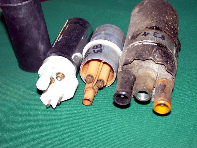
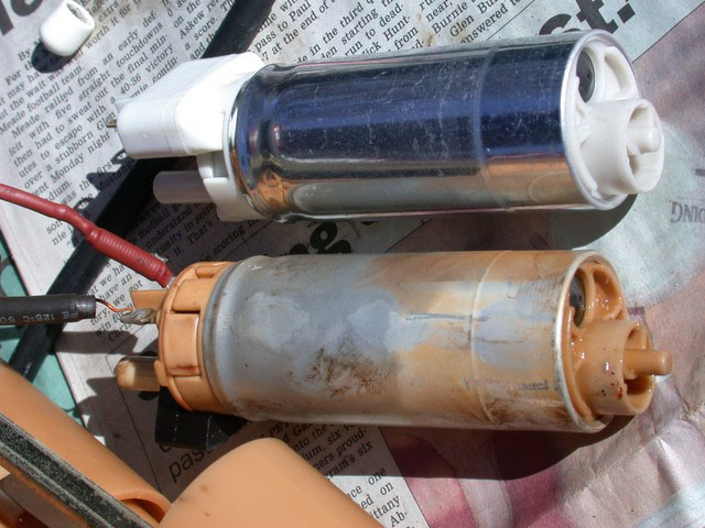
New Regina pump with protective sleeve removed compared with AC prepump and Bosch main pump from 83 B23F. I purchased the Regina pump after a short diagnostic session using an ammeter in series with the pump. The ammeter would fluctuate between about 1A and something above 5A. When it sank to 1A the idling car would die. Measuring the fuel pressure at the rail, crudely with a tire gauge, the same effect was seen - sometimes 25-30 lbs, other times about 5 lbs. This exercise is shown on a '92 940 with 142K miles. The in-tank pumps seem to last perhaps 150k miles.
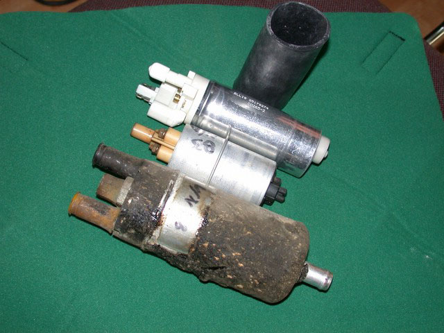
Note similarities between the two tank pumps on the left:
Parts Needs. [Editor] In addition to the pump and any associated in-tank hose or filter sock, you will in all likelihood need a new top gasket (p/n 1367623-4) and new hose clamps securing all the hoses on the top of the sender unit. These are almost always severely corroded. The large clamp holding the fill hose is Volvo p/n 943477-0; buy two of these. The smaller clamps are 943471-3; buy four of these. The spring clamps are 1321719-5; buy one of these unless you want to replace it with a screw clamp (recommended). If you do not have to remove all the hoses or if a clamp is reused, you'll end up with an extra clamp or so. Now is also the best time to replace the Volvo clamps with stainless Breeze Liner clamps which never, ever rust. You may also need a new 7.6mm ID in-tank pump hose (p/n 3514604-2): some pumps have been changed and the old hose is too short. Buy 14 inches. Inspect the main fill hose section between the fill pipe and the sender unit top: if it is torn, buy another. The large six inch clamp securing the threaded plastic ring screwed to the tank may be found at any hardware store.
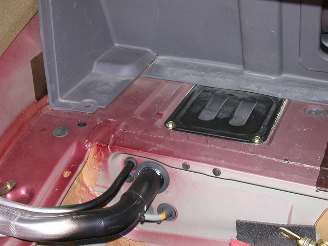
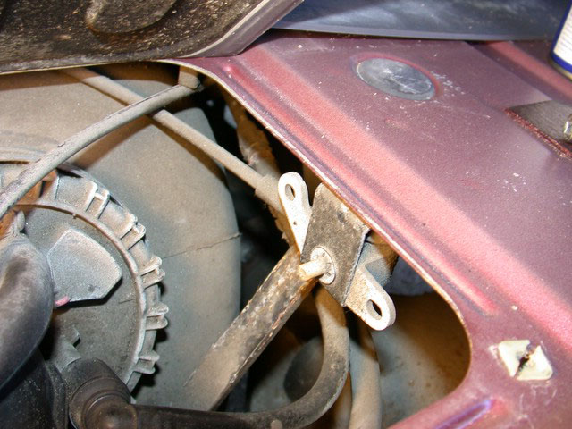
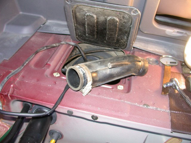
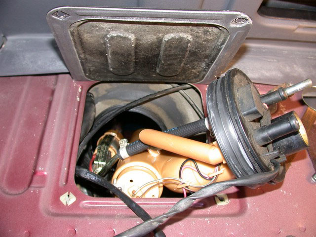
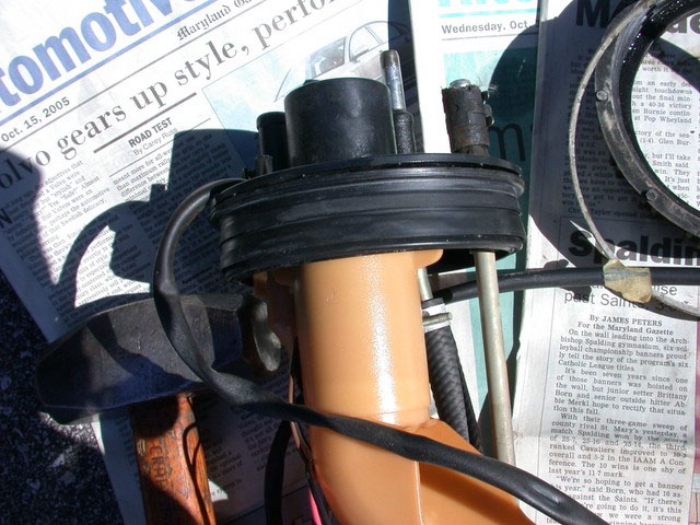
Procedure: Disconnect battery negative. Place a foam pad or rug on the bottom of the trunk for comfort as you lie there. Remove the body panel covering the fuel sender unit top. In the sedan, first remove the left side and center carpeted covers. The wagon hatch is under the forward cargo cover: remove the rear cover above the spare, then unscrew the front cover. You don't need to remove the vertical plastic trim piece in the photo below: just push it to access the front screws on the hatch:
After removing the access cover, note that the tank top is fairly well coated with road grime, but not rusty. [Editor:] most salt-belt cars are heavily rusted:
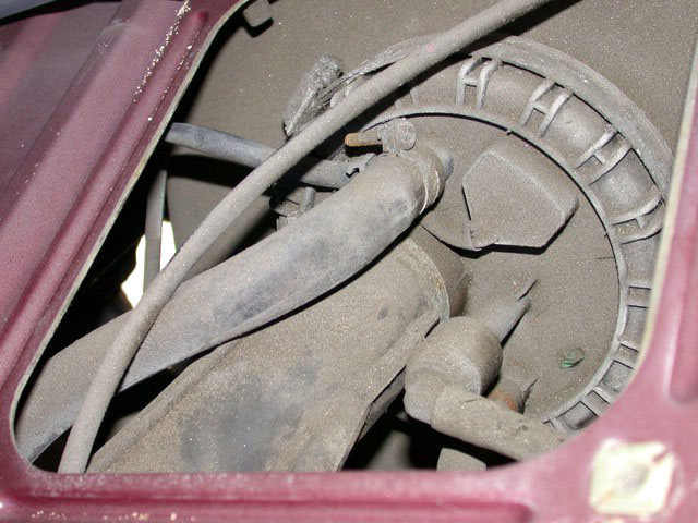
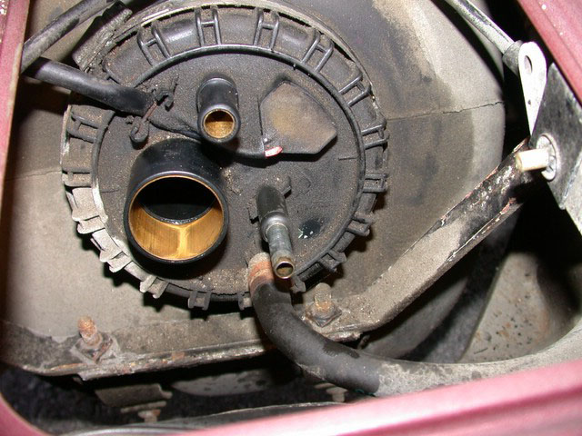
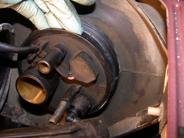
Following the pump outlet from the compression fitting at lower left the flare fitting junction with the steel feed line can be seen near upper right of opening:
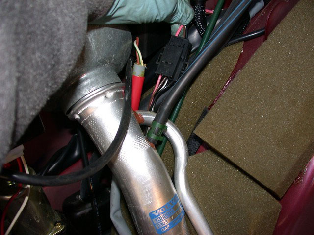
Make more access room by first disconnecting filler vent line. Be careful you do not damage the electrical wires:
Then disconnect filler hose:
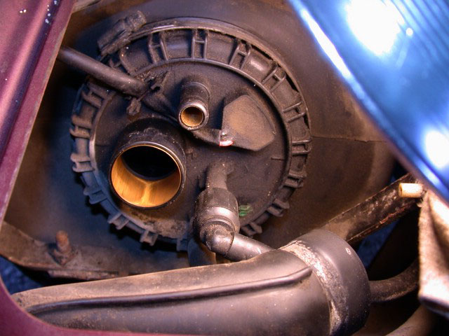
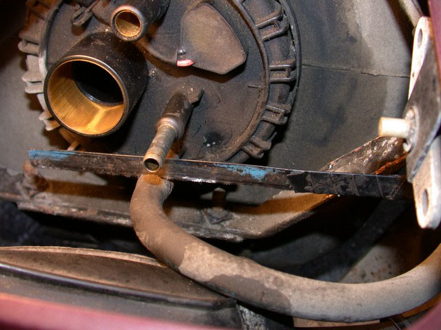
To remove the Volvo quick disconnect fitting on the fuel outlet line (the 90-degree fitting below), grip the outer sleeve, and push that outer plastic cylindrical sleeve towards the top of the fuel tank send unit. Keeping the sleeve pushed "forward", push the entire fitting towards the top of the tank. Press on the top of the quick release fitting. That push causes the entire fitting to move towards the send unit's top. That push releases the fitting from the send unit's steel tube. Then, pull the quick-release fitting from the send unit's steel tube. You may need a little penetrating oil to free up the inner o-rings from rust on the tube.
If you break this quick disconnect, the part number is "fuel feed line " Volvo p/n 9142814 consisting of the connector, the plastic line, and the metal line to under the car. To replace one, you'll have to drop the fuel tank for access to the other end of the metal fuel line. Rust may require that you buy new fittings as well on that end.
A Better Idea: [Jay Simkin] If the quick-release fitting indeed has been broken, you can install 1.5 inch long rubber fuel line hose and a 90-degree brass hose elbow from a plumbing supply store with barbs at each end (PEX (SharkBite) makes a 3/8" x 3/8" 90-degree brass elbow (Part #UC246LFA UPC is 6 97285 60489 6)). To attach
the brass elbow to the steel tube (at the top of the send unit), you'll
need to slide onto the steel tube, a 1.5 inch long length of fuel hose (fuel
injection-rated). The hose - if I recall correctly, should be 5/16" diameter (8mm +/-), which should also be the diameter of the barbed ends of the 90-degree elbow. The hose that goes onto the send-unit's tube should be about 1/2" (13 mm) longer than the steel tube is tall. Use dishwashing liquid to lubricate the steel tube, before pushing the hose onto it.
Before you push the brass elbow into the rubber tube, put three screw-operated hose clamps around the rubber hose, that you've slid onto the send unit's steel tube. Push the elbow into the rubber hose and put the hose clamps into place (two on the hose section that has been slid over the steel tube, and one clamp around the other end of the hose, into which the brass 90-degree elbow has been inserted. Snug, but do not tighten fully, these clamps. If you have a hard time inserting the barbed fitting into the plastic insert fuel line hose, applying heat to the end of the plastic-lined rubber hose will soften
the plastic so that the barbed hose connector can be pushed into place. You can use a hair dryer or heat the brass barb before inserting it, which is safer. You can also drill out a short length of plastic liner.
Next, cut a length of fuel hose to connect the brass elbow with the rubber fuel hose, that runs towards the engine. You'll need a brass straight hose splice. Put five more hose clamps onto the short section of new fuel injection hose, before sliding into it the brass splice tube. Then, slide the brass splice into one end of the fuel hose (that runs towards the engine) and also into the short length of fuel hose, that runs to the 90 degree brass elbow. Align the various hose sections, so that nothing is twisted or otherwise stressed. Tighten all clamps (two on either side of the straight hose splice, and one where the spliced hose goes onto the 90-degree brass elbow. Then tighten the hose clamps on the short section of rubber hose around the send unit's steel tube, and where that short section of hose, goes into the 90-degree elbow.
Once all clamps are full tighteened, you should have a vapor-tight connection.
A bit of discoloration on the outlet line indicates corrosion that may have helped bond the fitting to the line. Remove any corrosion after the unit has been removed (see below). [Note from Bruce Young] If the "quick disconnect" is absolutely stuck and you can't remove it, don't consider removing the steel fuel line to the filter. That requires massive disassembly: RR wheel, cat back exhaust, rear driveshaft half, parking brake cable, rear center console, rear seat bottom cushion, and peeling up rear carpet. Instead, replace it with SAE 30R9 fuel injection hose, safely routed and secured.
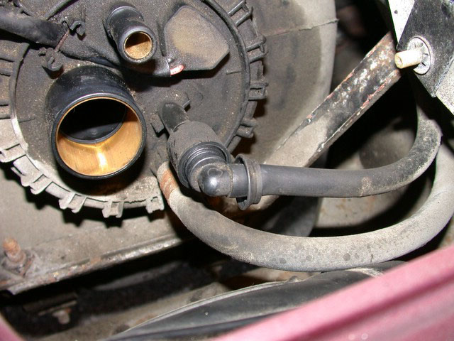
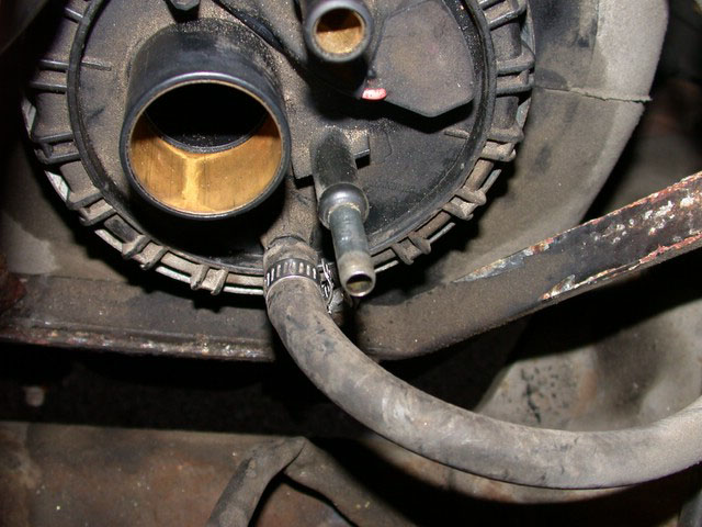
The fuel return line has a steel spring clamp (see previous photo above). To remove this intact, try adjustable water pump pliers or long, angled needle nose pliers. But: I have shot sparks when pliers slip off those clamps before, so with enough slack in the return line hose, I can cut the rubber hose about 3/4 inch from the end and save the spring clamp removal for the driveway when the sender is out (note: you should have enough slack in the hose to reinstall it without stretching):
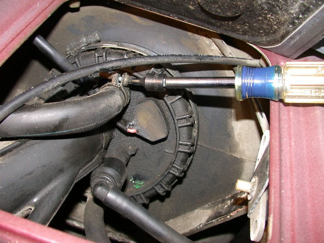
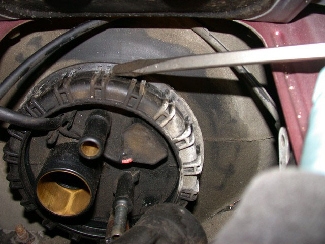
Tap the plastic lock ring loose. The threads are huge, so about two turns and it is off. [Editor] Don't use the screwdriver shown: use a piece of wood instead to avoid cracking it.
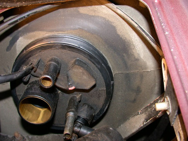
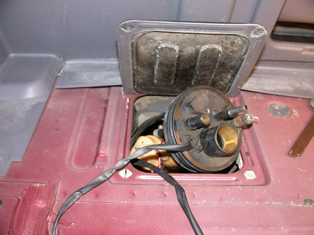
Everything is now loose but the electrical connections. Camera shows what the rag missed:
Separating the sender cap from the soft rubber seal underneath; the lip is only about 1/8 thick. [Jay Simkin] In the event you have a difficult time pulling the sending unit from the tank because it is stuck, use a flat-blade screwdriver with a wide tip (3/8") and a rubber mallet. Don't pull on the tubes that go through the sender's top. Tap gently against the sender unit's top lip. Using steel on (old) plastic requires that you go slowly. The send unit will back out.
Disconnect the sender wiring harness from the connector in the left side wheel well, then cut the zip ties holding the wire to the fill tube. Fish this harness out through the grommet hole near the fuel sender unit. There may be a wiring harness holder way up on the left under the deck: using a screwdriver, release the lock and pull the wires free.
The filler hose is in the way and must be removed from the filler pipe:
Now the unit can be withdrawn from the tank. Use a flashlight to see what is going on inside. Regina Pump: Notice the 90 degree CCW turn to bring it out of the tank at the right rear of the access hole. [Jay Simkin] Bosch Pump: The send unit's "barrel" - positioned just forward of the fuel tank's rear wall - points straight down (towards the tank's floor). In front of the send unit, there is a white plastic "baffle". It prevents fuel "slosh" (to keep the fuel gauge needle as stable as possible during turns, or sharp stops, etc.). The fuel send unit has to be maneuvered around this baffle. By turning the unit counter-clockwise (to your left, as you face the front of the car), to the 10 o'clock position, you move the barrel around the corner of the fuel tank baffle. At the same time as you move it, pull upwards and - as much as possible - tilt the top of the send unit towards the back of the car. This has the effect of lifting the end of the barrel so that it above the baffle. Once the barrel is clear of the baffle, you should be able to lift the unit out of the tank.
Pull it clear carefully. The Regina unit doesn't seem quite as fragile as I remember tank pumps on Bosch systems. [Jay Simkin] If the fuel pump's filter sock falls off in the tank - very unlikely, as it is press-fit onto the fuel pump's intake port - simply replace it the filter sock. It will do no harm sitting on the tank's bottom.
The large plastic lock ring is made of a polymer that shrinks over time, so if you are not planning to complete the job within about half a day, reinstall it to keep its shape or buy a new one. You can also soak it in hot water to expand it before installing.
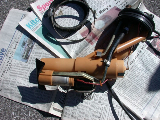
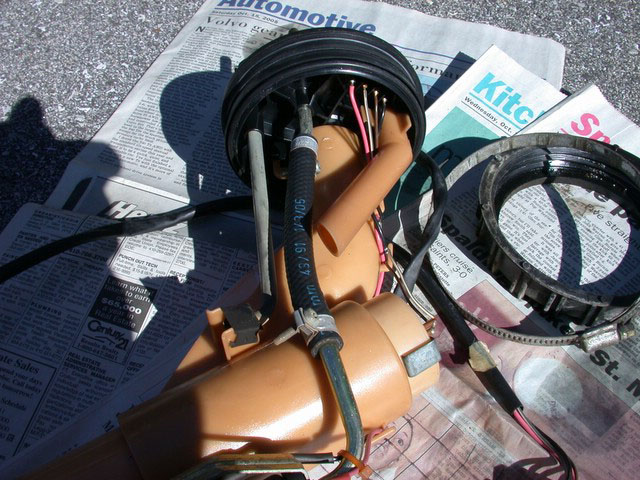
Two views of the Regina sending unit. Return line, feed line, and vent (L-R) can be seen joining the cap. The entire bottom end is spring loaded to ensure it meets the bottom of the tank, empty or full, cold or warm.:
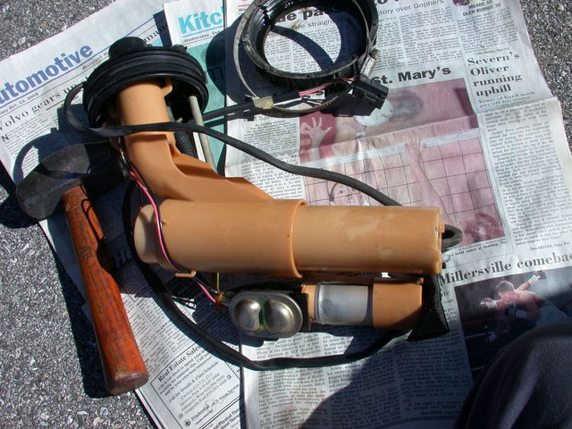
Turned over, the gauge sending unit in its sliding housing is rightmost. The double dished stamping on the Regina pump covers a small accumulator to smooth pump pulses (not used on Bosch):
Closeup of the tank seal. The inner edge is bifurcated to give what appears to be an elastic seal to the tank port's ID when the pressure inside exceeds atmospheric:
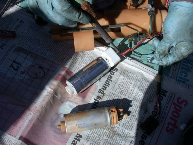
Removing the old pump and comparing it with the new one:
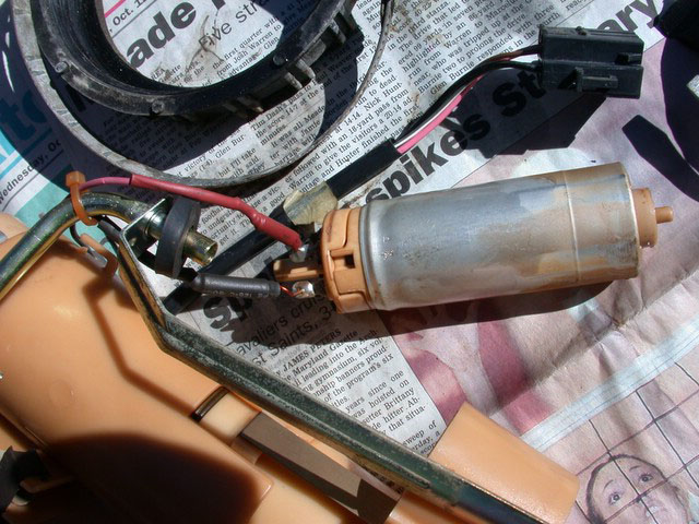
Soldering the leads onto the new pump (Note: the Volvo pump kits come with new crimp-on leads, but soldering them is a good idea):
Reassemble the pump and attach the filter sock at the bottom. Insert the top of the spring first, then pop the bottom in place. Make sure the little rubber button on the bottom of the spring is in place (see photo): 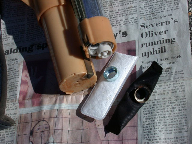
Electricals: Inspect the wiring harness. The insulation can chafe where it makes a 90 degree bend out of the sender unit top. If it is worn, apply liquid electrical tape to re-insulate. If your wiring harness securing spring rusted away, re-secure the wiring to the top of the sender using a big gob of silicone to act as a strain relief. Allow this to cure thoroughly before reinstalling else you risk jerking the wiring loose.
Corrosion: If you have the metal sending unit top, it will invariably be corroded. De-rust and treat with POR-15 to prevent future rusting. If your sending unit top is plastic, the metal fuel lines going through it will be rusted. Remove as much as you can, sand smooth, and treat the exposed areas with POR-15. Rust can creep down between the metal and plastic, swell, and crack the plastic sending unit top. De-rust to the extent you can and reinforce the joint between the tube and the plastic sender top with epoxy if this is the case. Now is a good time to replace all the hose clamps with new units. Breeze Clamps make an all-stainless clamp.
Gasket: Now is a good time to replace the fuel tank gasket if necessary. Lube the gasket surfaces - and the tank opening's inner surface - with vaseline. Do NOT lube the outer screw threads on the tank outlet or the plastic nut so as to not overtighten it on reinstallation.
Compressing the Sender Unit: The sender unit is spring loaded and collapses in itself about 5-6 inches as it rides up and down (like a telescope) within the larger part of the unit. Install it by collapsing using a string or a fishing line in order to install more easily. You can easily do this by looping the line over the pump clip on the barrel and feeding both ends of the loop up through the return line in the faceplate. Pull the barrel back by hand as far as it goes, pull the string tight and tie to a nearby neck or around a rod placed over the return line nipple. Once the sending unit is set in the tank you untie the string and pull one end out to remove the loop, letting the spring release properly into position. For the Bosch unit: use a long string, run it under the bottom of the pump through the notches, then up and out. Hold this slightly taut as you insert the unit into the tank so you can compress the sender once it is inside.
Installing Into the Tank: Take a good look at the yellowish anti-slosh pan on the bottom of the tank. See the high side and rear wall plates? You'll need to maneuver the assembly around them. Leaving the rubber seal off, insert the assembly in through the hole in the tank so that the bend in it points more-or-less at 3 o'clock. Push the assembly in some more while rotating it counterclockwise. [Jay Simkin] When installed, the fuel sending unit is located next to the back wall of the fuel tank. The fuel pump intake (the end with the filter "sock") needs to point straight down (towards the tank bottom) and to be parallel to the tank's rear wall. The reason: when going uphill with little fuel, the fuel will pool in back of the tank towards the vehicle's rear, where the pump can draw from it. To get the fuel send unit seated, it is necessary to swing it to your right (as you face the front of the car) so the end of the "barrel" can clear the in-tank baffles. Then, the top of the send unit needs to be lifted slightly and rotated forward towards the front of the car. This allows the end of the barrel to point straight down. You can then lower the unit into place. Regina System: Make sure you know when it's vertical. You'll need to clear the left-side edge of the anti-slosh pan on the bottom of the fuel tank. In order to achieve that, you don't want to push the assembly all the way into the tank - push it in only as far as you need to rotate it. To properly seat the bottom of the sender on the center of the slosh pan, you need to make the final 10-20 degrees of counterclockwise rotation with the assembly tilted up inside the tank so as to clear the edge of the pan. When the assembly has cleared the edge you'll be able to finally get it to vertical orientation (end of clockwise motion). Then push it in fully (2-3" deeper compared to where it should be right now). Make sure it seats properly. There are two small horizontal marks on the sender top that match two marks on the tank: make sure this orientation is correct. Bosch System: As you insert the unit into the tank, keep the string slightly taut. You will have to insert it first uncompressed, then as you maneuver the unit top past the lip into the tank, you can pull up on the string to compress the unit so the bottom of the sender clears the left side baffle and the filter and pump clear the front baffle walls. [Eric Cordis] Using the string, slightly compress the assembly prior to insertion. After you get it in and when almost vertical pull it together more, seat it then release the string after you have the unit installed and the ring on.
Seal installation: Since the in-tank side of the seal has two concentric lips, it's next to impossible to get it to seat while the seal is on the sender/pump assembly cover. Instead, you have to seat the seal in the opening and push the assembly through. Pull the sender assembly out so that the cover with its rim clears the tank. Apply some Vaseline on the inside and outside of the seal and onto the seal seating surfaces (cover and tank rim). All four surfaces (inside/outside of seal and mating plastic surfaces of tank and cover) must be slippery. Don't overdo it -- smear it thinly all over the seal and mating surfaces. Stretch the seal a tad and pull it over the sender assembly cover. Push the seal about halfway into the rim in the tank. With a rotating rocking motion (rock the sender in the seal slightly), slowly push the sender assembly's cover into the seal, and use it at the same time to fully seat the seal in the tank. After it's fully seated, pull the assembly out about 1/8". Feel the gap between the tank rim and the sender assy cover - make sure that the slight flange on the seal is present all around the cover. If you've pushed the seal improperly so that the flange made its way into the tank, pull the assembly out enough to be able to repeat pushing the seal halfway into the tank and following. With slight rocking, push the assembly back fully into the seal.
Replace the tank lock nut. Screw this down until it contacts the face of the sender top, then about 1/4 turn more to compress the gasket. If your locking ring did not come encircled with a large hose clamp (most 940s did: the clamp reinforces the locking ring), get a clamp. The hose clamp should initially be partly tightened and then in stages as the lock collar is being threaded on, ending up only just snug and not overtightened. The collar is only supposed to be hand-tightened, but when working through the access hatch it may be more difficult to accomplish adequate torque so you might LIGHTLY tap it counterclockwise using a piece of wood on the outer serrations and a mallet. The most important thing in getting a good seal is to have the sender face plate absolutely flush on top of the rubber gasket before installing the lock collar.
I replaced that awkward spring clamp on the return line with a screw clamp:
A view of the spring lock compression fitting on the feed line:
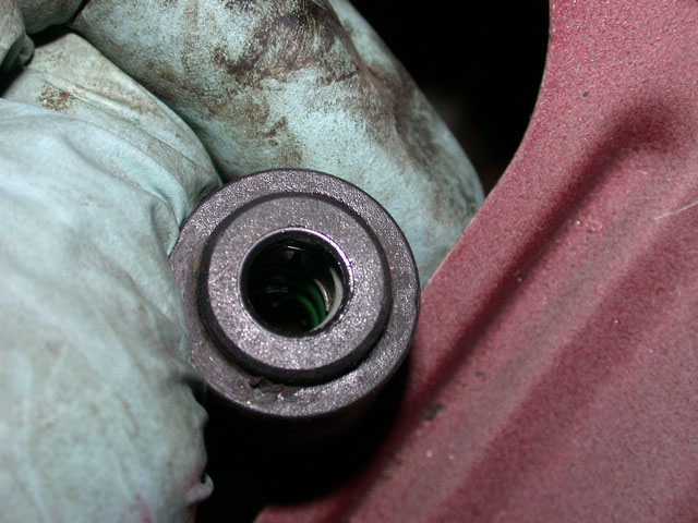
Clean out any penetrating oil or grease from this fitting and the fuel pipe. Make sure the green o-rings are correctly positioned inside. Install the sleeve by squeezing the cylinder and the 90 degree fitting together, then placing it squarely on the tube and pushing it home.
Apply grease to the fuel hose clamps to prevent future corrosion at the screws. Reassemble the fuel hose connections, reattach the electrical connector, push it into the wiring holder to the left of the hatch opening, under the deck, and use zip ties to secure it to the fill tube. Replace the tank access cover.
Testing: Start the car, pressurize the fuel system, then shut it down after a minute or so. After fifteen minutes, check carefully for leaks. Then reinstall the trunk fittings.
Failure mode of the old pump: brush, broken brush lead and spring connector, and commutator wear in this AC-made unit at 142k miles:

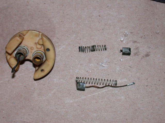
[Editor] My Bosch in-tank pump (95 940) failed at 183k miles from commutator wear just like Art's. The commutator was paper thin, worn into a deep dish. The brushes and leads were fine, though.
Fuel Tank Lock Ring [Dave Stevens] Proper tightening of the fuel sending unit plastic collar-type lock ring was a known problem area. There was even a recall associated with this for certain models. If you under-tighten these lock rings you risk fuel/vapor seepage at the top of the tank. If you over-tighten them you will jump the threads, which in turn can expand the collar and round the threads, making it difficult to properly tighten them. A new lock ring was normally required. But with the following simple procedures, most locking rings can successfully be re-used unless the threads are badly worn or the ring is badly misshapen. It's also the procedure that should be followed for new locking rings to properly tighten them and prevent damage in the first place. I started doing this when I was having problems re-installing the sending unit in my 89 740 and posted it here many eons ago. Volvo later started using the same fix (possibly a case of great minds thinking alike).
- Make sure the tank neck rubber gasket is clean and properly seated all the way around, i.e. no puckers or folds.
- Wipe out the thread area inside the lock ring collar and clean the thread area on the tank neck as needed.
- Make sure the mating surfaces on the top of the rubber gasket and the back of the sending unit face plate are clean. You can wipe a thin film of something like petroleum jelly around the top of the rubber gasket if you want to, but this really shouldn't be needed. Avoid lubing the threads.
- Make sure the sending unit face plate is going to sit nice and flat on the rubber gasket. If needed, bump the sending unit up and down a bit to help you position the end of the unit which will typically be resting on the bottom of the anti-splash bucket in the tank.
- And now for the secret ingredient. If there isn't one already present, go get a 5" stainless steel ring clamp from your favorite hardware store (most big-box stores like HD normally have them). I know the earlier (as in pre-1990) 700's didn't come with them, but Volvo did put them on the 900's, at least the later ones.Position the steel ring clamp on the lock ring (open the ring right up as needed) and lightly tighten to hold in place.
- Hand thread the lock ring onto the tank neck, but don't tighten it just yet.
- If you're having trouble starting the lock ring thread then here are some tips. To help avoid mis-threading, hold it on as level as you can and slowly turn it backwards (counter-clockwise) until you feel the ends of the threads jump/click, then start threading it on (clockwise). As noted above, clean the thread areas as best you can and only lube the threads as a last resort as this will just encourage over-tightening and thread jumping. Normally the lock rings aren't noticeably misshapen, but you can always run them under hot water (or apply hot rags) to make them more flexible if you think that will help. Don't use heat guns/hair driers near the tank to avoid the risk of explosion.
- Moderately tighten the steel ring clamp around the base of the lock ring collar (just above the bottom lip). Tighten it enough so that the ring won't expand during further hand tightening. If the lock ring has been previously jumping threads or you've had leaks then tighten the ring clamp a bit more to slightly compress the lock ring collar. Just make sure you can still hand turn it.
- Moderately tighten the lock ring by hand. Inspect around the inside of the lock ring. Make sure the gap between the bottom edge of the lock ring and the face of the sending unit is the same all the way around. If not then the sending unit isn't positioned flat on the rubber neck gasket -start again.
- Now hand tighten the lock ring as far as you can. If the threads jump, either tighten the steel ring clamp and try again or get a new lock ring.
- The lock ring is only supposed to be hand tightened, but as you're working through the access hatch you really aren't able to get as good a grip on it as needed and will want to tighten it a bit more.
- Tighten the steel ring clamp further to compress the lock ring collar enough to prevent the threads from jumping during the final tightening.
- Using a hammer and a wood stick (or whatever) as a drift, work around the outside ring at an angle lightly tapping the ridges a bit to further tighten it just to the point where you feel you've accomplished the next stage of tightening -typically another 1/8-1/4 turn. If you go 1/2 turn or more then either it wasn't fully hand tightened or you may have gone too far.
- Finally, really tighten that steel ring clamp to compress the lock ring collar around the neck.
Next time you gas-up, fill it close to the top. If you smell gas fumes under the left rear wheel well over the next few days (or the next hot day) then you likely haven't got the sending unit properly sealed. Open the access hatch and look for fresh stains on top of the tank. Re-seat and re-tighten as needed. If all else fails, get a new lock ring and/or rubber neck gasket.